Advertisement
Quick Links
Attention:
The use of Linear Amplifiers are controlled by specific laws wi-
thin the country of use. These laws must be known to the user
and are entirely the responsibility of the user. The manufacturer
declines any responsibility from unlawful use.
Warranty:
This product is covered by a 24 month warranty commencing from the date of purchase.
The original purchase receipt will be required for any claim. This warranty does not cov-
er aesthetic damage or damage to the RF power transistors from incorrect use.
KL503
HF 25—30 MHz Linear Amplifier
Specifications:
Operation Frequency:
25—30 MHz (10m Amateur HF Bands)
Modulation Types:
SSB,CW,AM, FM, (All narrowband modes)
Transistor:
8x RM 3 1x RM 4 MOSFET
Max I/P Current:
32A
Power Supply:
13.8VDC+/- 1V 40A
Input Fuse (Internal):
3x10A (Auto Fuse)
Input RF Power:
1-6W max (All modes)
Output RF Power:
300W max
Maximum bypass power (Amplifier off): 50W max
Input VSWR:
1.1—1.5:1
WARNING:
Before using this product please read carefully
all of the information in this manual or at least the quick start guide!!! To
avoid damage or incorrect operation this is extremely important!!!
Ver 2.0 Feb. 2021
Advertisement

Related Manuals for RM Italy KL503


Summary of Contents for RM Italy KL503
- Page 1 Attention: KL503 The use of Linear Amplifiers are controlled by specific laws wi- thin the country of use. These laws must be known to the user HF 25—30 MHz Linear Amplifier and are entirely the responsibility of the user. The manufacturer declines any responsibility from unlawful use.
- Page 2 Quick Start Guide: A more complete guide to the installation is featured later Connect the RTX input connector to transceiver with 50 Ohm patch cable Connect the ANT Output of the Amplifier to SWR Bridge / Wattmeter (If required), and then the An- tenna (50 Ohm load Impedance) Connect the Amplifier DC power Cable to a suita- ble 13.8VDC (±...
-
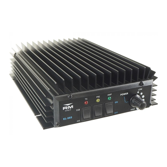
Page 3: Front / Rear Panel Description
KL503 Schematic Front / Rear Panel Description Front Panel AM / SSB Switch Receive Pre-Amplifier ON / OFF Switch Amplifier ON / OFF Switch TX indicator LED Pre Amplifier ON LED Amplifier ON LED Input Attenuator Rear Panel RTX SO239 RF input connector DC Input power connector. - Page 4 Installation: Typical Harmonic Output Unpack the amplifier from it’s shipping carton and inspect for any signs of damage. The amplifier should be installed (either fixed or mobile installation), in a place that allows good ventilation and provides a suitable base to support it. Failure to allow for reasonable ventilation will cause the amplifier to overheat and damage may occur.
- Page 5 The installation location must also provide a suitable ground system both for RF and the AC power supply, (if used). This is very important safety requirement for any radio trans- mission equipment but as power increases becomes increasingly important. A good RF ground will also help to prevent any returned RF from causing problems with the equip- ment.
- Page 6 The amplifier should give full output with approximately 4-5W input. Excessive input The KL503 is designed to work into a 50 ohms resistive load and any antenna outside of power should be avoided and the amplifier should always be operated in a responsible this requirement must use an antenna tuning unit between the output of the amplifier and manner.
Need help?
Do you have a question about the KL503 and is the answer not in the manual?
Questions and answers