Table of Contents
Advertisement
INSTRUCTION
MANUAL
Speco Technologies is constantly developing product improvements.
We reserve the right to modify product design and specifications without notice and without incurring any obligation.
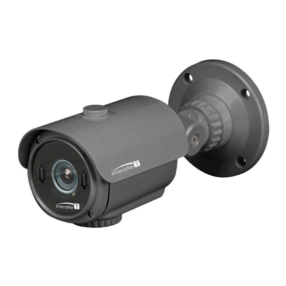
Intensifier T Series
HD-TVI Camera
HTINT70T, HTINT701T, HTINT702T
(Bullet Camera)
HTINT60T, HTINT601T
(Turret Camera)
HTINT591T
(Dome Camera)
HT7246T / HT7250T
(Dome Camera)
HTINT40T
(Miniature Camera)
Rev. 12/09/2016
Advertisement
Table of Contents


Need help?
Do you have a question about the HTINT701T and is the answer not in the manual?
Questions and answers