Dräger Regard 3900 Instructions For Use Manual
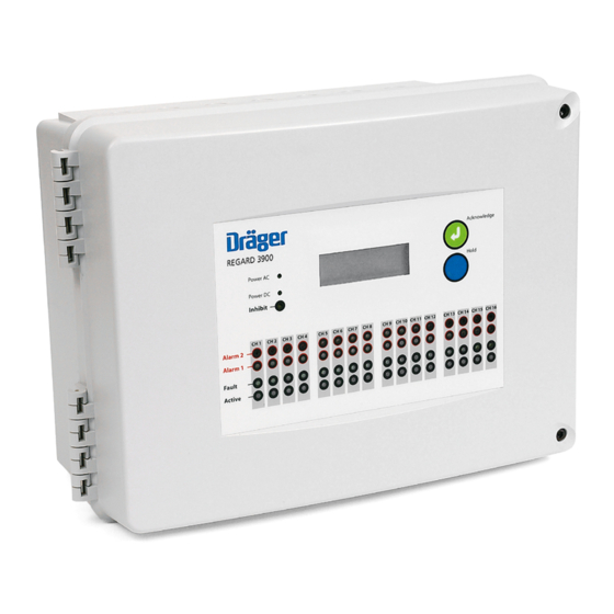
Regard 3900 series sixteen channel controller
Hide thumbs
Also See for Regard 3900:
- Installation, operation and maintenance manual (33 pages) ,
- Operating instructions manual (32 pages) ,
- Instructions for use manual (292 pages)
Table of Contents
Advertisement
Regard 3900 Series
Sixteen Channel Controller
Instructions for Use
WARNING
Strictly follow the Instructions for Use. The user must fully
understand and strictly observe the instructions. Use the
!
product only for the purposes specified in the Intended
Use section of this document.
i
Dräger. Technology for Life
®
Advertisement
Table of Contents

Subscribe to Our Youtube Channel
Related Manuals for Dräger Regard 3900


Summary of Contents for Dräger Regard 3900
- Page 1 Regard 3900 Series Sixteen Channel Controller Instructions for Use WARNING Strictly follow the Instructions for Use. The user must fully understand and strictly observe the instructions. Use the product only for the purposes specified in the Intended Use section of this document.
- Page 2 This page intentionally left blank...
-
Page 3: Table Of Contents
Disposal of electrical and electronic equipment ....................... 27 Technical data ................................28 10.1 Transfer function ................................29 Order list ..................................30 Annexe Configuring and calibrating a Regard 3920 controller ....................31 General ................................... 31 Main menu ..................................31 Information menu ................................32 Calibration menu ................................33 Settings menu ................................. 34 Regard 3900 Series... -
Page 4: For Your Safety
Indicates a potentially hazardous situation which, if not avoided, could result in physical injury or damage to the product or environment. It may also be used to alert against unsafe practices. NOTICE Indicates additional information on how to use the product. Regard 3900 Series... -
Page 5: Description
4–20 mA source output (transmitters that use a 4–20 mA sink output cannot be used). This document describes the Regard 3900 series used as a controller for a gas detection system. - Page 6 The controller also has the following ATEX marking: II (2) G WARNING This marking does not mean that the unit is “explosion proof”. The Regard 3900 series cannot be used in areas subject to explosion hazards (“hazardous areas”) without suitable protection. Regard 3900 Series...
-
Page 7: User Information
● Press Acknowledge / OK (or operate the remote reset if available) to clear an over-range indication. If it is pressed when the gas level is above the measuring range, the indication clears when gas level falls into the measuring range. Regard 3900 Series... -
Page 8: Alarm, Fault And Active Leds
The internal sounder emits an audible warning tone when A1, A2, A3, or F1 activates (not when F2 activates). The sounder also beeps every 30 seconds when alarms are inhibited. ● Press Acknowledge / OK (or operate the remote reset if available) to silence the sounder. Regard 3900 Series... -
Page 9: External Warning Devices
External warning devices External warning devices used with the Regard 3900 series controllers are activated by relays inside the controller, and are configured to meet the user’s gas detection requirements. The relays can be configured to operate in a number of ways: ●... -
Page 10: Technical Information
When required, use a suitable screwdriver to turn the control to adjust the contrast. Note that LCD screens are affected by temperature and adjustment may be required to suit very cold or very hot environments. 3801 Regard 3900 Series... -
Page 11: Input Module
A relay module is used to activate external warning devices (alarms, ventilators or other safety equipment) when alarm or fault conditions are sensed at the Regard 3900 series controller. The module has eight volt-free single-pole changeover relays of which one is a non-configurable system-fault relay (RL1) and seven are configurable relays (RL2 to RL8). -
Page 12: Output Module
If the inhibit switch is set to position 1 the output signals freeze at their current level. When the inhibit switch is returned position 0 the output signals return to the normal level. Output module fault If the output module has a fault, the output signal on all channels is 1 mA (± 0.3 mA). Regard 3900 Series... -
Page 13: Installation And Set Up
5. Refit and secure the two cover screws. Positioning and mounting the controller WARNING The Regard 3900 series controllers are not “explosion proof” and must not be installed in a hazardous area without additional Ex-protection. Observe the following instructions regarding the installation environment: ●... -
Page 14: Cable Entries
Cable screen earthing plate An earthing plate is available from Dräger to earth cable screen inside the panel of the Regard 3900 and 3920. When used, connect the plate to an external low-impedance earth using braided cable with a large cross-section. Note that the earthing plate is not required for the controller to meet the EMC directive. -
Page 15: Power Supplies
● If HART (highway addressable remote transducer) diagnostics can be used for the remote sensor transmitters, the supply must conform to the HART requirements (refer to the remote sensor transmitter operating manual). External +24 Vdc to 24 Vdc AC on input modules +24 V Fused Display board terminals 3810 Regard 3900 Series... -
Page 16: Installing Control Modules
Installing control modules WARNING Output modules are not included in the scope of the Regard 3900 ATEX EC-type examination. When an output module is fitted, the controller cannot be used for control of countermeasures against risk of explosion. The controller can have up to six control modules using the combinations detailed in Section 5.6.1. When fitting control modules observe the following: ●... - Page 17 Input modules Place a link on the relevant “Module Nr” terminals on the input module to determine the channel numbers in the Regard 3900 system. When numbering the input module observe the following: ● Each input module within the controller must have a different module number (1 to 4).
- Page 18 Installation and set up Relay modules Place a link on the relevant “Relays” terminals on the relay module to determine the relay numbers in the Regard 3900 system. When numbering the relay module observe the following: ● If there is only one relay module fitted, place the link on position 1–8.
- Page 19 The display board, relay modules and output modules do not require a separate DC supply. Note: For Regard 3910 non-standard cable lengths can be supplied by Dräger. The maximum permitted length of the ribbon cable is 2 metres (6.6 feet). 3816 Regard 3900 Series...
-
Page 20: Connecting Remote Sensor Transmitters
● Use screened cable if required by the transmitter. 5.7.1 Two-wire 4–20 mA transmitters Input module 0 V SIG 24 V 0 V SIG 24 V 0 V SIG 24 V 0 V SIG 24 V Channel 1 Channel 3 Channel 2 Channel 4 3817 Regard 3900 Series... - Page 21 ● Refer also to the instructions for the safety barrier and transmitter for connections between transmitter and barrier, and for the barrier earth connection. Input module Hazardous area Non-hazardous area 0 V RR 24 V 0 V SIG 24 V Safety barrier Transmitter +24 V +24 V Signal Signal 3819 Regard 3900 Series...
- Page 22 5.7.3 Three-wire 4–20 mA transmitters ● Only connect transmitters that have a 4–20 mA source output. Regard 3900 cannot be used with a three-wire transmitter that has a 4–20 mA sink output (if necessary use a sink-to-source converter). ● The module can supply up to 400 mA to a three-wire transmitter.
-
Page 23: Connecting Other Remote Devices
● When an internal supply is required to drive the external device, use an output from the power supply unit (PSU). ● The figures below show the relay contacts when relays are in the non-alarm or non-fault state. Input or relay module Input or relay module Energize on alarm Normally energized 3822 Regard 3900 Series... - Page 24 ● Each channel output is a current source that will only work when connected to a passive load. Output module (10) (11) (12) – – – – – – – – Channel 1 Channel 2 Channel 3 Channel 4 External device 3823 Regard 3900 Series...
-
Page 25: Configuring And Calibrating The Controller
Configuring and calibrating the controller The configuration and calibration tools for Regard 3900 series controllers are used to view and change the configuration of the controller, including the combination of internal control modules and the settings for the gas detection and warning devices. The tools also allow zero point and span calibration. -
Page 26: Troubleshooting
Faulty output module Replace output module Output constant but gas-level on Alarms inhibited Return inhibit switch to position 0 display screen changing Output signal too low or will not reach Load resistance too high Reduce load resistance 20 mA Regard 3900 Series... -
Page 27: Polytron Remote Sensor Transmitter Faults
Observe EN 60079-29-2 and any relevant national regulations in the country of use. There are no specific maintenance tasks for the Regard 3900 controller. Carry out any maintenance or calibration tasks in line with the instructions and frequency described in the remote sensor transmitter operating manual. -
Page 28: Technical Data
Technical data Technical data Control panel versions (Regard 3900 and 3920) 415 × 305 × 175 mm (16.3 x 12 x 6.9 in.) Dimensions Weight Approximately 5 kg (11 lb) Material ABS – VO Ingress protection IP65 Cable entries M20 (qty 30) -
Page 29: 10.1 Transfer Function
4.3 to 20 mA Linear gas reading according to selected range 3.7 to 4.3 mA < 3.7 mA Under-range or maintenance, depending on fault trip level Gas concentration reading for 0–100 % LEL Input signal (mA) 3904 Regard 3900 Series... -
Page 30: Order List
Order list Order list NOTICE Regard 3800 series components are not compatible with the Regard 3900 series. Always refer to the relevant Regard series order list when ordering parts and accessories. Description Quantity Order code Regard 3900 (control panel with display board) -
Page 31: A Configuring And Calibrating A Regard 3920 Controller
Language – Selects the on-screen language (the settings menu is always in English). Information – Enters the information menu (see Section A.3 on Page 31). Calibration – Enters the calibration menu (see Section A.4 on Page 32). Settings – Enters the settings menu (see Section A.5 on Page 33). Regard 3900 Series... -
Page 32: Information Menu
Test LEDs – Activates the LED and display screen test (see Section 3.7 on Page 9). Press OK to start and stop the test. Tags – Displays all channel tags (read only). Modules – Displays all module types and versions (read only). Regard 3900 Series... -
Page 33: Calibration Menu
4. Enter the transmitter signal, and then select Calibrate channel. ○ When the success message appears, exit the menu to save the calibration. ○ If a failure message appears, refer to the troubleshooting information (see Section 7 on Page 26). Regard 3900 Series... -
Page 34: Settings Menu
A2 relay – Sets the A2 (alarm 2) relay latching or non-latching. If a Regard 3900 series controller is used for flammable gas detection to protect against risk of explosion, at least one gas alarm relay should be set latching. (See EN 60079-29-1:2007 Explosive atmospheres – Gas detectors – Performance requirements of detectors for flammable gases.) - Page 35 A3 alarm). Also select Rising or Falling to set the alarm to activate for rising or falling gas levels. F1 / F2 trip level – Enter a fault alarm trip level between 1 mA and 3.8 mA (setting F2 to zero switches off the F2 alarm). Regard 3900 Series...
- Page 36 Alarm type – Select the alarm or fault required (A1, A2, A3, F1 or F2). Energize mode – Select energize on alarm or normally energized. Latch – Select latching or non-latching. Acknowledge – Select acknowledgeable or non-acknowledgeable. Regard 3900 Series...
- Page 37 This page intentionally left blank Regard 3900 Series...
- Page 38 Draeger Safety UK Limited US Distributor: Draeger Safety, Inc. Ullswater Close 101 Technology Drive Riverside Business Park Pittsburgh, PA15275-1057 Blyth Northumberland NE24 4RG Tel +1 412 787 8383 Tel +44 1670 352891 Fax +1 412 787 2207 Fax +44 1670 544475 www.draeger.com www.draeger.com 4208800...
Need help?
Do you have a question about the Regard 3900 and is the answer not in the manual?
Questions and answers