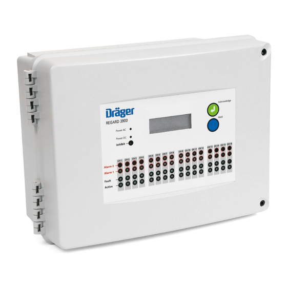
Dräger REGARD 3900 Installation, Operation And Maintenance Manual
One to sixteen channel controller
Hide thumbs
Also See for REGARD 3900:
- Instructions for use manual (38 pages) ,
- Operating instructions manual (32 pages) ,
- Instructions for use manual (292 pages)

Related Manuals for Dräger REGARD 3900


Summary of Contents for Dräger REGARD 3900
- Page 1 Dräger REGARD 3900 One to Sixteen channel controller Installation, operation and maintenance guide Rev 1 – December 2005...
- Page 2 Contents FOR YOUR SAFETY........................3 INTENDED USE.......................... 4 CE mark ........................... 4 DESCRIPTION ..........................5 General............................. 5 Main display board........................5 4-20mA input module ........................ 8 Relay module .......................... 10 INSTALLATION ........................13 Installation environment ......................13 Mounting..........................13 Cable entries ........................... 14 Power supply ..........................
-
Page 3: For Your Safety
FOR YOUR SAFETY Follow the instructions Follow the instructions for installation, operation and maintenance. Maintenance The equipment must be inspected and serviced regularly by trained personnel. Keep a record of inspections and servicing. Repairs of this apparatus should only be carried out by competent personnel. We recommend that either a training course or service contract is obtained from Draeger and that all repairs are carried out by them. -
Page 4: Intended Use
The REGARD 3900 is suitable for use in residential, commercial and industrial environments. The controller is not designed or certified for use in areas where combustible or explosive gases, vapours or dust mixtures are likely to occur. -
Page 5: Description
DESCRIPTION General The REGARD 3900 is a standalone, self-contained gas detection system compris ing of an enclosure complete with a display board, and up to four individual input/output modules. The combination of input/output modules is flexible and is matched to the application or solution. All input/output modules are connected together via a ribbon cable to make up the complete system solution. - Page 6 Note 1 – Very low gas values of ± 2% of measuring range will be displayed as zero. • If the transmitter signal exceeds 20mA the display for that channel shows: The Over-range indication remains on the display even after the transmitter signal falls below 20mA. Press Acknowledge to reset the display.
- Page 7 LEDs Alarm 1, Alarm 2, Fault, Active When LED is… It means… Flashing A2 alarm tripped Alarm 2 Steady A2 alarm acknowledged but gas present No alarm condition Flashing A1 alarm tripped Alarm 1 Steady A1 alarm acknowledged but gas present No alarm condition Flashing Fault alarm tripped...
-
Page 8: Ma Input Module
Hold Action Effect Press for < 1sec Engage/disengage “scroll lock”: Engaged: only channels currently on display shown Disengaged: all channels displayed sequentially (Only applies when more than four channels displayed.) Press and hold for > 1sec Shows measuring range Internal controls and indicators Sounder (buzzer) A sounder on the display board gives a local audible notification of Alarm 1, Alarm 2 or Fault 1 alarm. - Page 9 Each input module must have a different module number. Set the first physical module as number 1, the next as number 2, and so on. A module’s number determines the channels on that module: Module No. Channels 1 – 4 5 –...
-
Page 10: Relay Module
The remaining seven relays are fully configurable. A maximum of two relay modules can be installed in the REGARD 3900 if there is enough room. A single relay module will work with up to 12 input channels or two relay modules will work with up to 8 input channels. - Page 11 Single fault F1 F1 trips on one specified channel Single F2 F2 trips on one specified channel “Alarms inhibited” Inhibit switch on the display board is in moved to position “1” * Depending on the whether the relay is set as ‘energise-on-alarm’ or ‘normally energised’. Common, voted and single relays do not change state if the Inhibit switch is in position “1”...
- Page 12 When you have two relay modules the 16 relays are numbered as follows: Link Relay on module……… number in system RL1 ........1 RL2 ........2 RL3 ........3 RL4 ........4 RL5 ........5 RL6 ........6 RL7 ........7 RL8 ........
-
Page 13: Installation
Locate the REGARD 3900 where the display and indicators are easily seen, and controls are accessible • The REGARD 3900 is not “explosion proof” and may not be installed in an hazardous area without additional Ex-protection • Avoid locations where excessive vibration is possible •... -
Page 14: Cable Entries
Note – 4 The gland earth plate is not required for Regard 3900 to meet EMC Directive. Power supply The REGARD 3900 can be operated from an AC supply when using a 24V DC power supply inside the enclosure, or from an independent external 24V DC supply. - Page 15 The display board and relay modules do not need a DC supply connection. External DC supply To power the controller from external 24V DC, use a regulated, noise-free 24V DC supply. If the DC input is likely to be subject to high levels of conducted RF noise, use a filter to remove the noise. If there is a requirement to use HART diagnostics for the field transmitters the power supply used must conform to the requirements of HART (refer to the transmitters Operating Manaual).
- Page 16 Example: $& ,1 $& 2 1 ' ,63/$< % 2 $ 5 ' 9 ' & 72 ,1 38 7 9 ' & ,1 0 2 ' 8 / ( 6 % $ 7 7 ( 5 < Optional: when the controller is supplied with both AC and DC, connect the output of the primary 24V supply to the AC ON input on the display board.
-
Page 17: Connecting Transmitters
Connecting transmitters Two-wire 4-20mA transmitters Use screened cable if required by the transmitter. P $ ,1 3 8 7 0 2 ' 8 / ( & + $ 1 1 ( / & + $ 1 1 ( / & + $ 1 1 ( / &... - Page 18 Regard 3900 will work with any three-wire 4-20mA transmitter with a 4-20mA source output (maximum supply current 400mA). Regard 3900 will not work three-wire transmitters that have a 4-20mA sink output. If necessary, use a sink-to-source converter. If the transmitter requires more than 400mA operating current, connect the transmitter’s supply terminal directly to the power supply.
- Page 19 Short-circuit fault indication for three-wire transmitters To ensure that a short circuit between the 4-20mA output and 0V at the transmitter causes a fault indication at the controller, the cable resistance must not exceed the value given by the following formula: ×...
- Page 20 Two-wire 4-20mA transmitter with safety barrier The following diagram shows the general arrangement. Refer to specific instructions for safety barrier and transmitter for connections between transmitter and barrier, and for instruction for earthing of barrier, where necessary. Use screened cable if required by the transmitter Rev 1 –...
-
Page 21: Remote Reset
Remote reset If remote reset is required, connect a normally-open switch across the terminals. Close the contacts momentarily to acknowledge or reset alarms. It is sufficient to connect the remote reset switch to one input module only. When the connection is closed, all acknowledgeable relays in the system will be reset. -
Page 22: Configuration And Calibration
CONFIGURATION AND CALIBRATION Set input module number If you have more than one input module you must set the module number of each module using the hardware links on the modules. Fit a jumper on the link marked with the number. Each module must have a different module number. -
Page 23: Display Board
Inhibit switch in position “0” the fault alarm will trip. Configuration Once the REGARD 3900 is mechanically assembled its configuration needs to be set. Refer to the REGARD 3900 Config guidance document. The parameters which require setting are Rev 1 – December 2005... -
Page 24: Calibrating 4-20Ma Inputs
4 mA for a zero gas reading. The display of the REGARD 3900 will indicate zero for a transmitter signal of 4mA ± 0.3mA. If necessary, calibrate the transmitter to give 4.0mA at zero gas. - Page 25 • When the calibration confirmation message appears, verify that the REGARD 3900 display reading corresponds to the gas concentration • Remove the calibration gas. If controlling the transmitter output: • Set the output of the transmitter to a value between 10mA and 20mA.
-
Page 26: Maintenance
MAINTENANCE Check the controller for operation regularly. The transmitters may require periodic recalibration. Refer to the instruction manual for the transmitters for guidance. Observe EN 50073 and respective national regulations. LED and display test To test the LEDs and LCD display, press and hold the Acknowledge and Hold buttons at the same time. -
Page 27: Other Information
Replace input module. Fault LED lit for a Check transmitter connections. group four Check system ribbon cable. channels. Replace input module. Input module fitted, Check system ribbon cable. but no LEDs lit or data Check internal power distribution wiring. Check display board. module. -
Page 28: Specifications
SPECIFICATIONS System 415mm × 305mm × 150mm Dimensions Weight Approx. 5kg Enclosure material ABS – VO Colour Grey Mounting External (M6), Internal Ingress protection IP65 (with external mounting brackets) Cable entries M20 (preformed) Cable cross-section 2.5mm (minimum 0.5mm AC input voltage Depends on power supply. -
Page 29: Ma Module
Max. switching voltage 250VAC, 100V DC Max. switching current Min. switching voltage Min. switching current 100mA 4-20mA module Transmitter input 2 or 3 wire 4-20mA (3 wire source transmitters only) Transmitter supply 24V DC (nominal), max. 400mA Remote reset 2 wire normally open switch input Relays A1, A2 &... -
Page 30: Part Numbers
4208792 Power cable (short – module to module) 4208791 Regard 3800 modules, boards and accessories will not work on Regard 3900 and vice versa. Regard 3800 and Regard 3900 modules and boards are not interchangeable. Rev 1 – December 2005... -
Page 31: Enclosure Dimensions
Enclosure dimensions The dimensions given below are for the standard enclosure. It is recommended that a 50mm space is left around the total enclosure when installed. Available space to the left of the enclosure may be required to accommodate the opening profile of the enclosure. 403 mm Rev 1 –... -
Page 32: Rev 1 – December
Draeger Safety UK Ltd Kitty Brewster Industrial Estate Blyth, Northumberland NE24 4RG United Kingdom +44 1670 352891 +44 1670 544475 Manual part number 4208800 Rev 1 – December 2005...
Need help?
Do you have a question about the REGARD 3900 and is the answer not in the manual?
Questions and answers