Dräger Regard-1 Instructions For Use Manual
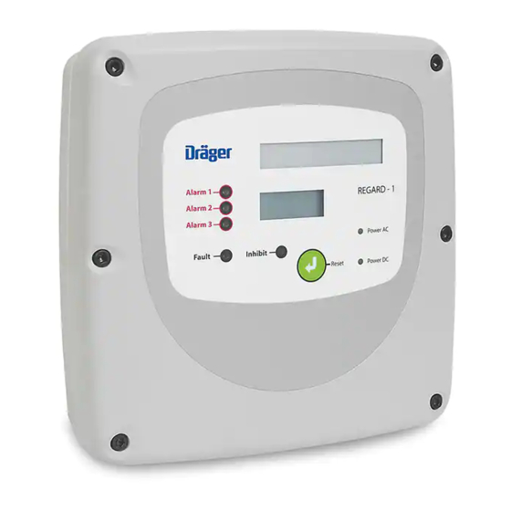
Single channel controller
Hide thumbs
Also See for Regard-1:
- Installation, operation and maintenance manual (64 pages) ,
- Installation, operation and maintenance manual (48 pages)
Table of Contents
Advertisement
Advertisement
Table of Contents

Subscribe to Our Youtube Channel
Related Manuals for Dräger Regard-1


Summary of Contents for Dräger Regard-1
- Page 1 Regard-1 Single Channel Controller Instructions for Use WARNING Strictly follow the Instructions for use. The user must fully understand and strictly observe the instructions. Use the equipment only for the purposes specified in this document. ® Dräger. Technology for Life...
-
Page 3: Table Of Contents
Connecting transmitters and sensors ......14 Other inputs and outputs ..........17 Configuration and calibration .......20 Setting the measuring range and TWA function ..20 Calibrating the Regard-1 controller ......21 Setting the alarm operating modes ......23 Setting the alarm thresholds ........24 Troubleshooting .............26 Maintenance ............27 Disposal ..............27... -
Page 4: For Your Safety
Indicates a potentially hazardous situation which, if not avoided, could result in physical injury or damage to the product or environment. It may also be used to alert against unsafe practices. NOTICE Indicates additional information on how to use the product. Regard-1 Single Channel Controller... -
Page 5: Description
Regard-1 4–20 mA ● Low-voltage directive 2006/95/EC. for use with a 4–20 mA transmitter; or Regard-1 SE Ex for use with an SE Ex sensor. The internal components and settings The controller also carries the following ATEX marking:... -
Page 6: User Information
Additionally, the A2 alarm can be set to be acknowledgeable. When the A2 alarm is set to be acknowledgeable, the alarm device connected to the A2 alarm output can be switched off or silenced when the alarm condition is still present. Regard-1 Single Channel Controller... -
Page 7: Power Leds
○ Cancels other on-screen messages (for example: an over range (-Or-) message). ● Pressing and holding the reset button for approximately 10 seconds resets the TWA value to zero (display message: tA-0) and restarts the TWA calculation period. Regard-1 Single Channel Controller... -
Page 8: Technical Description
A3 relay output 26 27 28 Fault relay output 29 30 31 Inhibit relay output N E L 98 to 253 Vac fused output (500 mA max.) (back row terminals) 98 to 253 Vac input (front row terminals) Regard-1 Single Channel Controller... -
Page 9: Display Board
Page 13). To adjust the TWA calculation period or to set the TWA alarm relay requires additional software which is available from Dräger. Contact Dräger for details. 3434 Regard-1 Single Channel Controller... - Page 10 When connected to a PC, data is sent by the controller as ASCII characters (see Section 10 on Page 28 for the datalog specification). Additionally, the gas level and TWA are printed on screen every second in the following format: Gas 20.1 TWA 0.1 Regard-1 Single Channel Controller...
-
Page 11: Installation
The Regard-1 controller is supplied configured for use with a Positioning the controller 4–20 mA transmitter or an SE Ex sensor but can be adapted to be used with the other detector type. -
Page 12: Controller Set Up
2. Fit the pellistor board on to SK2. the backup power supply information (see Section 5.4.2 on Page 13). If the pellistor board is removed, ensure that the links are refitted to position A–E on SK2. Regard-1 Single Channel Controller... -
Page 13: Power Supplies
3 m. Connect an external AC supply (98 to 253 Vac) to the input (NEL) front row terminals or connect an external DC supply (18 to 30 Vdc) to the 24 V battery terminals. 3437 Regard-1 Single Channel Controller... -
Page 14: Connecting Transmitters And Sensors
5.5.2 Three-wire 4–20 mA transmitter ● Only connect a transmitter that has a 4–20 mA source output. Regard-1 cannot be used with a three-wire transmitter that = 800/I is the maximum resistance per core from has a 4–20 mA sink output. - Page 15 ● Use cable with braided copper screen. Hazardous Area Non-Hazardous Area Main board Safety barrier Transmitter +24 V +24 V Signal Signal 3425 Regard-1 Single Channel Controller...
- Page 16 Dräger SE Ex sensor. Connecting when the controller is powered will damage the sensor. ● The Regard-1 controller cannot be used with Dräger SE Ex LC sensor. ● Use cable with braided copper screen. ● The maximum cable resistance is 6 Ω per core. The table below shows the maximum cable length according to the cross-sectional area, using a typical connector cable.
-
Page 17: Other Inputs And Outputs
(non-alarm or non-fault) state. A1 relay A2 relay TWA relay 14 15 16 17 18 20 21 22 Main board A3 relay Fault relay Inhibit relay 23 24 25 26 27 29 30 Main board 3438 Regard-1 Single Channel Controller... - Page 18 ● The voltage output decreases as the current drawn increases, as shown in the table below. Output voltage Current drawn 22 V 30 mA 18 V 100 mA A1 switched output Main board 10 11 3424 A2 switched output Main board 12 13 3421 Regard-1 Single Channel Controller...
- Page 19 ● Use cable with braided copper screen. Main board External device 4-20 mA 3444 Transmitters and sensors For installation and maintenance instructions of the transmitter or sensor that is connected to the controller refer to the relevant transmitter/sensor instruction manual. Regard-1 Single Channel Controller...
-
Page 20: Configuration And Calibration
● Use switch SW1-F on the display board to set the TWA function (for all firmware versions). SW1-F 3439 r1.00 or r2.00 firmware Measuring range 0–1 0–3 0–5 0–10 0–25 0–30 0–50 0–100 0–200 0–250 0–300 0–500 0–1000 0–2000 0–2500 0–3000 0–5000 0–9999 Regard-1 Single Channel Controller... -
Page 21: Calibrating The Regard-1 Controller
3. If the controller has a display, confirm that the reading is correct. If the reading is incorrect, recheck the measuring range and the transmitter calibration. Calibration is complete – go to the alarm operating modes section (see Section 6.3 on Page 23). Regard-1 Single Channel Controller... - Page 22 9. 2.24 g. Reconnect all power supplies to the controller, and 2.40 allow the sensor to settle for at least five minutes before 2.56 continuing with zero and span calibration. 2.72 Regard-1 Single Channel Controller...
-
Page 23: Setting The Alarm Operating Modes
Additionally the A2 alarm can be set to be acknowledgeable. 3441 A1 alarm Mode of operation Rising Falling Non-latching Latching A2 alarm Mode of operation Rising Falling Non-latching Latching Not acknowledgeable Acknowledgeable Regard-1 Single Channel Controller... -
Page 24: Setting The Alarm Thresholds
(not possible for some transmitter types). 4. Adjust the simulated gas signal to set the voltage across TP1 and TP2 to match the required alarm threshold (see the gas detection or the oxygen deficiency/enrichment table). Regard-1 Single Channel Controller... - Page 25 7. After setting all alarm thresholds, adjust VR1 so that the voltage across TP1 and TP2 is 800 mV ± 20 mV. NOTICE Regard-1 SE Ex has a fixed fault alarm threshold at about -5% of the measuring range. 3441 3.
-
Page 26: Troubleshooting
Incorrect gas reading on the display Incorrect measuring range set Set the correct measuring range (see Section 6.1 on Page 20) Water ingress Faulty seal Check and repair the cover sealing ring, cable entries or battery breather if fitted Regard-1 Single Channel Controller... -
Page 27: Maintenance
August 2005 and apply to this device. Common household appliances can If batteries are fitted to the Regard-1 controller, maintain the be disposed of using special collecting and batteries in accordance with the instructions of the battery recycling facilities. -
Page 28: Technical Data
RS-232 output in ASCII (American Standard Code for Information Interchange) format Data rate: 2400 baud Data bits: 8 Stop bits: 1 Parity: none Flow control: Xon / Xoff Transfer function (4-20mA input) The display reading for an input signal between 1.0mA and 21.0mA is linear. Regard-1 Single Channel Controller... -
Page 29: Order List
Order list Order list Description Part number Regard-1 single channel controllers Regard-1 4–20 mA 4208585 Regard-1 SE Ex 4208600 Accessories and spare parts Pellistor board 4208582 Options board 4208583 Lead-acid batteries (qty 2) 4208586 Display board V1 4208581 Display board V2... - Page 30 This page intentionally left blank Regard-1 Single Channel Controller...
-
Page 31: Annexe A - Front Panel Labels
0 – 100 / 300 / 1000 Unit Ammonia (NH Range 0 – 100 / 300 / 1000 Unit Oxygen (O %vol rising/falling Range 0 – 5 / 25 / 100 %vol rising/falling Unit %vol %vol rising/falling Range Unit Range Unit Regard-1 Single Channel Controller... - Page 32 This page intentionally left blank Regard-1 Single Channel Controller...
- Page 34 Draeger Safety UK Limited US Distributor: Draeger Safety, Inc. Ullswater Close 101 Technology Drive Blyth, NE24 4RG Pittsburgh, PA 15275-1057 United Kingdom +44 1670 352891 +1 412 787 8383 +44 1670 544475 +1 412 787 2207 www.dräger.com www.dräger.com 4208591 © Dräger Safety UK Limited Edition 08 –...
Need help?
Do you have a question about the Regard-1 and is the answer not in the manual?
Questions and answers