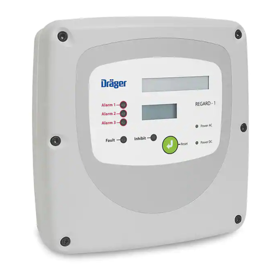
Dräger REGARD-1 Installation, Operation And Maintenance Manual
Single-channel controller
Hide thumbs
Also See for REGARD-1:
- Installation, operation and maintenance manual (64 pages) ,
- Instructions for use manual (34 pages)

Related Manuals for Dräger REGARD-1


Summary of Contents for Dräger REGARD-1
- Page 1 REGARD-1 Single-channel controller Installation, operation and maintenance Issue 6 – December 2006...
-
Page 2: Table Of Contents
Contents FOR YOUR SAFETY ....................3 INTENDED USE......................4 CE marking and ATEX approval................5 Other tests and approvals ..................5 Special conditions for safe use................5 DESCRIPTION ......................6 Main board ......................7 Display board ......................10 Pellistor board ....................... 11 Options board...................... -
Page 3: For Your Safety
FOR YOUR SAFETY Follow the instructions Follow the instructions for installation, operation and maintenance. Maintenance The equipment must be inspected and serviced regularly by trained personnel. Keep a record of inspections and servicing. Repairs of this apparatus should only be carried out by competent personnel. We recommend that either a training course or service contract is obtained from Draeger and that all repairs are carried out by them. -
Page 4: Intended Use
Both units are suitable for use in residential, commercial and light industry environments. The Regard-1 controller is certified according to the directive 94/9/EC (ATEX Directive) to be operated with performance approved 4-20mA transmitters (EC-type examination certificate BVS 03 ATEX G 011X), or with Dräger SE Ex pellistor measuring heads. -
Page 5: Ce Marking And Atex Approval
Regard-1 4-20: if used with a transmitter whose output current can be below 20mA for concentrations above full scale, set the alarm relays latching. Regard-1 SE Ex: set at least one alarm relay – the one with the highest alarm level – to be latching. -
Page 6: Description
DESCRIPTION The unit is available in two versions: 4-20mA or SE Ex, with or without gas level display. An additional “Options board” is available that provides an isolated 4-20mA output, TWA alarm relay and data logger with RS-232. Two 1.2AH lead-acid batteries can be fitted inside the unit’s enclosure to provide continued operation for several hours if AC power is interrupted. -
Page 7: Main Board
Main board 1. Terminals for batteries or external DC input. 2. Connector for display board. 3. Potentiometers for A1 – A3 alarms and display adjustment. 4. Terminals for field devices. 5. Connector for Options board. Issue 6 – December 2006... - Page 8 Field devices terminals Function External reset input Reset 4-20mA output (requires Options board) - 20mA + 24 VDC unswitched output (100mA max.) - 24V + 4-20mA transmitter or SE Ex sensor input - Input + 10- 11+ A1 24V switched output (100mA max.) 12- 13+ A2 24V switched output (100mA max.) 14 15 16...
- Page 9 24 V battery terminals For continued operation of the controller when the AC supply fails connect two 12V 1.2AH lead-acid batteries in series to the battery terminals. If unsealed batteries are fitted, that could generate hydrogen when charged, drill a vent hole in the top of the enclosure.
-
Page 10: Display Board
Display board The display shows the gas level, or indicates that the gas level exceeds the measuring range (over-range) or is below the measuring range (under-range). Examples 0.50 Normal gas level display. Negative display reading. A negative display reading - 0.5 may be caused by inaccurate calibration or by drift or temperature effect of the sensor. -
Page 11: Pellistor Board
The pellistor board supplies a constant current to the sensor and amplifies the signal from the sensor. To fit the pellistor board to a Regard-1 4-20: x Remove all the links from SK2 on the main board x Fit the pellistor board onto SK2... - Page 12 RS-232 data logger output When the Options board is fitted, the 4-20mA output is on terminals 3 and 4 of the main board and the TWA relay output is on terminals 20 to 22. The RS-232 datalogger output is on an RJ11-style 4-position/4-conductor socket. RJ11 socket RS 232 Sub D –...
-
Page 13: Installation
INSTALLATION Installation environment When selecting the installation place, consider the following:: x Locate the unit where the display and indicators are easily seen, and controls are accessible x The equipment is not “explosion proof” and must not be installed in a hazardous area without additional Ex-protection. -
Page 14: Ac Supply
Mounting points dimensions (not to scale): Use a hole cutter to make the cable entries. Do not attempt to “knock out” the cable entries. AC supply Connect a permanent AC supply to the unit. If the AC supply to the unit is from an AC socket, the maximum allowed length of cable between the socket and the unit is 3m. -
Page 15: Connecting Transmitters And Measuring Heads
4-20mA transmitter + 24V 4-20mA signal Three-wire 4-20mA transmitter Only for a transmitter with 4-20mA source output. Regard-1 will not work with a three- wire transmitter that has a 4-20mA sink output. Use cable with braided copper screen. Regard-1 main board... - Page 16 Regard-1 to the transmitter, cable is the transmitter operating current (in mA) This formula assumes that the three cores of the connecting cable each have the same resistance.
- Page 17 Polytron SE Ex (Pellistor) measuring head Use cable with braided copper screen. Do not connect the sensor/measuring head when the controller is powered: this will damage the sensor. Maximum cable resistance The maximum allowed cable resistance is 6 ohms per core with the Dräger SE Ex sensor.
-
Page 18: Relay Outputs
Relay outputs Relay contacts when relays are in their normal state (ie, no alarm): A1 relay A2 relay TWA relay A3 relay Fault relay Inhibit relay The fault relay is energised in its normal state (ie, when there is no fault) Unscreened cable can be used for relay outputs. - Page 19 Output voltage and current The voltage at each output decreases as the current drawn from the output increases. Output Current voltage available 22 V 30 mA 18 V 100 mA Issue 6 – December 2006...
-
Page 20: Remote Reset Input
Remote reset input To acknowledge and reset alarms remotely from the controller, connect a normally- open switch to the remote reset terminals. Close the contacts momentarily to acknowledge / reset alarm(s). Use cable with braided copper screen. Issue 6 – December 2006... -
Page 21: Configuration And Calibration
CONFIGURATION AND CALIBRATION Set measuring range Use switch SW1 on the display board to set the display measuring range. The number of decimal places is fixed according to the measuring range. For display board with r1.00 or r2.00 firmware*, set the range using this table: Measuring range 0 - 1... - Page 22 * The firmware version is shown on the display for a few seconds after the unit is turned on. For display board with r1.01 or r2.01 firmware, set the range using this table: Measuring range 0 - 1 OFF OFF OFF OFF OFF 0 - 3 OFF OFF OFF OFF 0 - 5...
-
Page 23: Calibrating A 4-20 Unit
Calibrating a 4-20 unit (Also refer to the transmitter’s operating manual for calibration instructions.) Zero calibration There is no zero adjustment for the 4-20 unit. The controller will indicate zero for a transmitter signal of 4mA ± 0.3mA. If necessary, calibrate the transmitter to give 4.0mA at zero gas. - Page 24 Location of FS (span adjust) potentiometer: FS: span adjust If controlling the transmitter output: x Adjust the output of the transmitter to 20mA if possible; otherwise to a value between 12mA and 20mA. x Adjust potentiometer FS on the main board until the voltage across TP1 and TP2 corresponds to the transmitter output.
-
Page 25: Calibrating An Se Ex Unit
Calibrating an SE Ex unit Use the controls on the pellistor board to set sensor current, calibrate zero and calibrate span: (Also refer to the measuring head’s operating manual for calibration instructions.) Set the sensor current 1. Set the sensor drive current range with SW1-A on the pellistor board. For all Dräger sensors, set SW1-A to OFF. - Page 26 Do not connect the sensor/measuring head when the controller is powered: this will damage the sensor. Calibrate zero x Connect a voltmeter across TP1 and TP2 on the main board: x Apply known clean air – free of flammable gas – or verify that no flammable gas is present at the sensor.
- Page 27 2. Apply calibration gas Use a calibration gas with concentration between 40% and 60% of the measuring range. x Apply gas using calibration adaptor at 0.5 l/min flow rate. x Allow display reading to settle (about 2 to 3 minutes) x Adjust VR3 on the pellistor board until the voltage across TP1 and TP2 corresponds to the concentration of the calibration gas.
-
Page 28: Configuring Alarms
Regard-1 4-20: if used with a transmitter whose output current can be below 20mA for concentrations above full scale, set the alarm relays latching. Regard-1 SE Ex: set at least one alarm relay – the one with the highest alarm level – to be latching. - Page 29 A2 alarm Mode of operation Rising Falling Non-latching Latching Not acknowledgeable Acknowledgeable A3 alarm Mode of operation Rising Falling Non-latching Latching Fault alarm Mode of operation Non-latching Latching x The A1, A2 and A3 relays energise on alarm. x The Fault relay de-energises on alarm (ie, is normally energised). Issue 6 –...
- Page 30 Setting alarm thresholds on 4-20 units Use the potentiometers marked A1, A2 and A3 on the main board to set the alarm thresholds: A1 pot. A2 pot. A3 pot. For safety relevant decisions only use status of Alarm/Fault LEDs and relays. Do not use display reading.
- Page 31 Using a 4-20mA source loop calibrator x Connect the loop calibrator between terminals 7 and 8. The method to set the alarm thresholds is the same for each. To set A1 alarm 1. Turn A1 potentiometer fully clockwise 2. Adjust test pot until voltage across TP1 and TP2 is at the required threshold 3.
- Page 32 For oxygen deficiency and enrichment alarms, use this table to determine alarm thresholds for a 0 – 25% range: Alarm threshold Transmitter signal Voltage across (mA) TP1 & TP2 (V) 14.9 2.98 15.5 3.10 16.2 3.24 16.8 3.36 (Normal reading) 18.1 3.62 18.7...
- Page 33 Setting alarm thresholds on SE Ex units Use the potentiometers marked A1, A2 and A3 on the main board to set the alarm thresholds: Use VR1 on the pellistor board to simulate a sensor signal. Measure the voltage across test points TP1 and TP2 to determine the alarm threshold.
- Page 34 After setting the alarm thresholds, adjust VR1 so that the voltage across TP1 and TP2 is 800 mV ± 20 mV. Regard-1 SE Ex has a fixed fault alarm threshold at about –5% of the measuring range. Issue 6 – December 2006...
-
Page 35: Maintenance
MAINTENANCE Check the unit for operation regularly. Service the controller every 12 months. The transmitter or measuring head may require periodic recalibration. Refer to the instruction manual for the transmitter or measuring head for guidance. If batteries are fitted to the control unit then these batteries should be maintained in accordance with the instructions of the battery manufacturer. -
Page 36: Specifications
SPECIFICATIONS Regard-1 4-20 Regard-1 SE Ex 270 mm u 270 mm u 90 mm Dimensions Mass (without Approx. 2.5 kg batteries) Housing material ABS – VO Ingress protection IP 65 Cable entries 6 No. M20 AC supply voltage 98 to 253 VAC, 50-60 Hz... -
Page 37: Part Numbers
Stop bits: output Parity: none Flow control: Xon / Xoff Part numbers Description Part number Regard-1 4-20 4208585 Regard-1 SE Ex 4208600 Accessories and spare parts Pellistor board 4208582 Options board 4208583 Lead-acid batteries (2 off) 4208586 Display board V1... -
Page 38: Ec Type-Examination Certificate
EC type-examination certificate Issue 6 – December 2006... - Page 39 Issue 6 – December 2006...
- Page 40 Issue 6 – December 2006...
- Page 41 Issue 6 – December 2006...
- Page 42 x Display board V2.0 is not included in the scope of this type-examination. x The options board is not included in the scope of this type-examination. Issue 6 – December 2006...
-
Page 43: Ec Declaration Of Conformity
EC Declaration of Conformity DECLARATION OF CONFORMITY Draeger Safety UK Ltd Kitty Brewster Industrial Estate Blyth, Northumberland NE24 4RG England declare that REGARD–1 in accordance with Directive 94/9/EC (Equipment and protective systems intended for use in potentially explosive atmospheres), is in conformance with the EC-Type Examination Certificate BVS 03 ATEX G 011 X for equipment group and category... - Page 44 Issue 6 – December 2006...
- Page 45 Front panel labels Methane (CH %LEL Range 0 – 100 %LEL Unit %LEL %LEL Hydrogen sulphide (H Range 0 – 20 / 50 / 100 Unit Carbon monoxide (CO) Range 0 – 100 / 300 / 1000 Unit Ammonia (NH Range 0 –...
- Page 46 Issue 6 – December 2006...
- Page 47 Issue 6 – December 2006...
- Page 48 Draeger Safety UK Ltd Kitty Brewster Industrial Estate Blyth Northumberland NE24 4RG United Kingdom +44 1670 352891 +44 1670 544475 Manual part number 4208591 This manual supersedes and replaces the following manuals: 4208603 issue 1 4208591 issue 5 For use with display board firmware r1.00 and r1.01. Issue 6 –...
Need help?
Do you have a question about the REGARD-1 and is the answer not in the manual?
Questions and answers