
Related Manuals for Jensen JCR-175A


Summary of Contents for Jensen JCR-175A
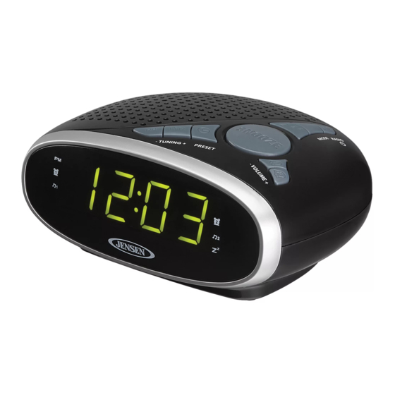
- Page 1 DIGITAL AM/FM DUAL ALARM CLOCK RADIO MODEL: JCR-175A USER MANUAL PLEASE READ THIS USER MANUAL COMPLETELY BEFORE OPERATING THIS UNIT AND RETAIN THIS BOOKLET FOR FUTURE REFERENCE.
-
Page 2: Important Safety Instructions
WARNING TO PREVENT FIRE OR SHOCK HAZARD, DO NOT USE THIS PLUG WITH AN EXTENSION CORD, RECEPTACLE OR OTHER OUTLET UNLESS THE BLADES CAN BE FULLY INSERTED TO PREVENT BLADE EXPOSURE. TO PREVENT FIRE OR SHOCK HAZARD, DO NOT EXPOSE THIS APPLIANCE TO RAIN OR MOISTURE. - Page 3 does not fit into your outlet, consult an electrician for replacement of the obsolete outlet. 10. Protect the power cord from being walked on or pinched particularly at plugs, convenience receptacles, and the point where they exit from the apparatus. 11.
-
Page 4: Compliance With Fcc Regulations
Changes or modifications not expressly approved by the party responsible for compliance could void the user’s authority to operate the equipment. ® DEAR JENSEN CUSTOMER Selecting fine audio equipment such as the unit you’ve just purchased is only the start of your musical enjoyment. Now it’s time to consider how you can maximize the fun and excitement your equipment offers. -
Page 5: Important Notes
The serial number of this product is found on its bottom cover. You should note the serial number of this unit in the space provided as a permanent record of your purchase to aid in identification in the event of theft of loss. Model Number: JCR-175A Serial Number: ________________ IMPORTANT NOTES Avoid installing the unit in locations described below: ... -
Page 6: Battery Installation
during a power outage, but all clock settings and radio presets will be kept in memory. You may need to make a slight adjustment to the time once the power returns if the outage is for a long period of time. BATTERY INSTALLATION Open the BATTERY COMPARTMENT DOOR on the bottom of the cabinet. -
Page 7: Location Of Controls And Indicators
LOCATION OF CONTROLS AND INDICATORS 1. MULTI FUNCTION LED DISPLAY 12. EXTERNAL FM WIRE ANTENNA 2. MUSIC (RADIO) ALARM 1 13. RADIO ON/ STANDBY / INDICATOR ALARM OFF BUTTON 3. BEEPING ALARM 1 INDICATOR 14. MODE BUTTON SLEEP BUTTON 4. PM INDICATOR 5. -
Page 8: Setting The Clock
OPERATING INSTRUCTIONS SETTING THE CLOCK When you connect the radio to an AC outlet for the first time the clock display will begin flashing "12:00". The flashing will stop when you set the time. 1. If clock display is not flashing, press and hold the button in unit standby mode, display will start flashing to enter clock set mode. -
Page 9: Recalling A Preset Station
for example, it stops on 88.9 MHz instead of 88.8 MHz, use the manual tuning method to “fine tune” to the exact frequency of the desired station. TIPS FOR BEST RADIO RECEPTION AM - The AM antenna is built inside the radio. If AM reception is weak, change the position of the unit until the internal antenna picks up the strongest signal. -
Page 10: Wake To Radio
3. Tap the MINUTE button repeatedly to set alarm minute. Press and hold the button for fast advance setting. 4. Tap the corresponding alarm button to finish the setting. Note: There is a PM INDICATOR located on the left-hand side top corner of the clock display. -
Page 11: Sleep Operation
following day. 4. If you do not want the beeping alarm to turn on the following day, tap the corresponding alarm button repeatedly until associated alarm indicator goes off from display. SNOOZE After the radio or alarm sounds, you may press the SNOOZE button for a few more minutes sleep. -
Page 12: Care And Maintenance
few seconds before show current time. 5. The volume level can now be controlled through the main unit. Operate all other functions on the auxiliary device as usual. Notes: If you connected the Line-out Jack of your external device then you only need to adjust the volume control of this unit. - Page 13 an aim to conserve and maintain the environment through responsible recycling. Please visit us at http://www.spectraintl.com/green.htm for more information on Spectra’s green initiatives or to find a recycler in your area. 90 DAY LIMITED WARRANTY AND SERVICE VALID IN THE U.S.A. ONLY SPECTRA MERCHANDISING INTERNATIONAL, INC.
- Page 14 warranty service and repair of the unit without cost. Also include a note with a description explaining how the unit is defective. A customer service representative may need to contact you regarding the status of your repair, so please include your name, address, phone number and email address to expedite the process.
Need help?
Do you have a question about the JCR-175A and is the answer not in the manual?
Questions and answers