Advertisement
Table of Contents
- 1 Led Display
- 2 Table of Contents
- 3 Product Information and Precautions for Installation
- 4 Preparation for Cabinet Installation
- 5 Frame Installation
- 6 Cabinet + Frame Installation
- 7 SBOX Connection
- 8 Settings and How to Use
- 9 Issue and Solution
- 10 Cable Connection
- 11 Seam Adjustment
- Download this manual
Advertisement
Table of Contents

Subscribe to Our Youtube Channel
Related Manuals for Samsung LH015IFH SERIES


Summary of Contents for Samsung LH015IFH SERIES
-
Page 1: Led Display
Samsung Electronics LED Display Installation Manual LH015IFH*** (P1.5) LH020IFH*** (P2.0) LH025IFH*** (P2.5) SBB-SNOWH3U Ver. 1.0... -
Page 2: Table Of Contents
Table of Contents Samsung Electronics 1. Product Information and Precautions for Installation 2. Preparation for Cabinet Installation 3. Frame Installation 4. Cabinet + Frame Installation 5. SBOX Connection 6. Settings and How to Use 7. Issue and Solution 8. Cable Connection... -
Page 3: Product Information And Precautions For Installation
1. Product Information and Samsung Electronics Precautions for Installation • Frame Kit Composition Refer to Page 8 Frame Kit Composition Note FHD Installation CY-LFH15FWA (18 Set) for P1.5 Standard FHD Installation CY-LFH20FWA (32 Set) for P2.0 Standard FHD Installation CY-LFH25FWA 10*5 Fig.1 (6*3) - Page 4 1. Product Information and Samsung Electronics Precautions for Installation • Precautions for Installation (LED damage) Image Precautions [ Beware of Outside Impact, Fall] ▶ Beware not to cause any impact on the LED screen or drop the product on the MODULE floor after the protection gets taken off for installation.
- Page 5 1. Product Information and Samsung Electronics Precautions for Installation • Preparations for Installation LED MODULE JIG (-) (+) Driver (model name: CY-LJFNAS) 10.0mm Wrench Electric Driver Service JIG Plier Antistatic Holder Magnet Tool (BH81-00001A) Glove...
-
Page 6: Preparation For Cabinet Installation
2. Preparation for Cabinet Installation Samsung Electronics • Preparations Before Installation SLIDING SCREW (In Exclusive Frame Accessory) 9 Page - ⓓ IB & cable Top-Cushion Outermost Hole LED set handle Push Hook Area Bottom-Cushion Fig.1 Box Opening Fig. 2 Handle Fig.3 Cover Connector... - Page 7 2. Preparation for Cabinet Installation Samsung Electronics Switch Button Screw Cushion Top Fig.5 Check the Screen Fig.7 Cabinet Storage Fig.6 Cover Corner Removal ⑤ Check whether there is any abnormality on the screen by connecting the power cable .(Fig.5) ※ Press the ‘Switch’ button for five(5) seconds after applying the electricity.
- Page 8 2. Preparation for Cabinet Installation Samsung Electronics ◈ Reference : Process of Screen check Power In Switch Button Power out ◇ Connect Power Cable to SET. Use internal pattern to check dead pixel or any damage with screen ※ Internal white pattern :...
- Page 9 2. Preparation for Cabinet Installation Samsung Electronics ⑧ Attach the PET Sheet and assemble Cover PCB for the Cabinet that is located at the exterior. ※ PET Sheet & Cover PCB should be at the boundary of whole screen. (Blue area at the exterior of Fig.1) ※...
-
Page 10: Frame Installation
3. Frame Installation Samsung Electronics • Frame Kit Composition CY-LFH15FWA CY-LFH20FWA CY-LFH25FWA Item 10X5 Units Units Units ⓐ ASSY BRACKET SIDE ⓑ ASSY BRACKET CENTER ⓒ ASSY BRACKET JIG ⓓ ASSY SLIDING SCREW ⓔ ASSY ANCHOR SCREW ⓕ MANUAL-INSTALL Size of the Installation Screen(mm) 2880X1620... - Page 11 3. Frame Installation Samsung Electronics ① Put the ⓐBracket Side the end of the left side and then fasten the screws to install. (Fig.3) ※ After fastening one(1) screw, use the device for vertical positioning to set up straight vertical alignment. Then fasten up the remaining holes.
- Page 12 3. Frame Installation Samsung Electronics ※ Precautions for Fastening the Screws...
- Page 13 3. Frame Installation Samsung Electronics Wrong Installation Correct Installation Wall ⓐ, ⓑ ⓒ Fig1. Check the Hole Fig2. Fix the Jig (Screw) Fig3. Fasten the Screw ② Install ⓑBracket Center. Fig4. Maintain the Parallel Frame ※ First, check the Hole to fix the ⓒ JIG. [Fig.1] ※...
-
Page 14: Cabinet + Frame Installation
4. Cabinet + Frame Installation Samsung Electronics • Fix I/G Location ① Install I/G first on the back side of the Cabinet of each Type (Fig.1) ※ Location to Install: Locate the I/G at the point 35~40mm below, which is the standard for carving at the right side of the frame, and then fasten the screws.(Fig.2) - Page 15 4. Cabinet + Frame Installation Samsung Electronics ② Adjust the Corners of the Cabinet to each of the cravings to be closer to the Frame. ※ Order of Cabinet Installation (13 Page Fig. 1) ※ Check whether all the four(4) bolts are put into the frame. (Fig.1) ③...
- Page 16 IG Box Protection Samsung Electronics To prevent unexpected removing IG box, the Protection Bracket should be attached on left / right side of the display (Fig.1) * In case of pocket installation, do not need to attach the protection.
-
Page 17: Sbox Connection
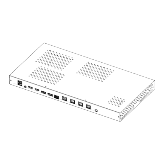
5. S-BOX Connection Samsung Electronics ① Input the video signal to the S-BOX. (Input terminal : HDMI, DP) ② Check the signal input from SOURCE STATUS.(RED : HDMI1 , GREEN : HDMI2, Blue : DISPLAY PORT) ③ Connect from the HDBT OUT port of S-BOX to HDBT IN port of Interface Gender using LAN cable. - Page 18 5. S-BOX Connection (Redundancy) Samsung Electronics ① If Redundant Spec should be used, Connect from DATA IN port of Interface Gender to DATA OUT port of the last cabinet by using OCM Cable. • For HDBT signal stability, use the cable above CAT6 SFTP level.
-
Page 19: Settings And How To Use
6. Settings and How to Use Samsung Electronics 6-1 Control Program for PCs LSM(LED Signage Manager) LSM Download Path : GSBN - SLM - Display solution download -> "LED SIGNAGE MANAGER" or "LSM“ • - GSBN : http://v3.samsunggsbn.com/ep... - Page 20 6. Settings and How to Use Samsung Electronics 6-1 Control Program for PCs LSM(LED Signage Manager) Software that adjusts the LED Cabinet Layout in Remote • S-box Ethernet PC and S-box should be connected through Ethernet connection. HDBT Control PC...
- Page 21 6. Settings and How to Use Samsung Electronics 6-1 Control Program for PCs LSM(LED Signage Manager) Start– Login Page • If the LSM gets operated for the first time, the page to set the password will appear. To set the password, users have to input the same password two times and then click the “Start”...
- Page 22 6. Settings and How to Use Samsung Electronics 6-1 Control Program for PCs LSM(LED Signage Manager) New Connection • To add connection information, you can either use Search function or input the IP address by yourself. If you click on the Search button, the IP addresses available on S-BOX in the same network will appear.
- Page 23 6. Settings and How to Use Samsung Electronics 6-1 Control Program for PCs LSM(LED Signage Manager) New Connection-Connect • When you are using the previous version of S-BOX, select “Without Cabinet IP” option. If you are using UHD S-BOX, select “With Cabinet IP (UHD)”...
- Page 24 6. Settings and How to Use Samsung Electronics 6-1 Control Program for PCs LSM(LED Signage Manager) Main Window-Home Window • Home Screen : Information of the connected device, input source, cabinet composition, and error device are shown.
- Page 25 6. Settings and How to Use Samsung Electronics 6-1 Control Program for PCs LSM(LED Signage Manager) Main Window-Home Window • Input source: Input source, resolution, connection time of S-BOX are shown. Cabinet Layout : Layout, number of units, number of connections and number of disconnections in all LED cabinets are shown.
- Page 26 6. Settings and How to Use Samsung Electronics 6-1 Control Program for PCs LSM(LED Signage Manager) Main Window-Edit Connection Layout Window • Connection layout: The location and the layout of each LED cabinet are adjusted in the output source area of the S-BOX.
- Page 27 6. Settings and How to Use Samsung Electronics 6-1 Control Program for PCs LSM(LED Signage Manager) Main Window-Connection Window • Device connection list view: Check S-BOX composition, modify and delete S-BOX connection, show by each LED Cabinet Group Connection layout (View Port):...
- Page 28 6. Settings and How to Use Samsung Electronics 6-1 Control Program for PCs LSM(LED Signage Manager) Main Window-Connection Window - Device Information/Setting View • 1. Basic : . Power On/Off, Change input source, Screen Mute / Freeze 2. Picture . Change Picture Mode, Brightness / Contrast...
- Page 29 6. Settings and How to Use Samsung Electronics 6-1 Control Program for PCs LSM(LED Signage Manager) Main Window-Connection Window - Device Information/Setting View • 6. Cabinet Settings . ABL, Gamut, Backlight . Software Update function (FPGA, Calibration data, etc.) 7. Cabinet Calibration .
- Page 30 6. Settings and How to Use Samsung Electronics 6-1 Control Program for PCs LSM(LED Signage Manager) Main Window-Connection Window - Sub Information View • Monitor Window: Checking MDC communication log and connected device information available, able to be extracted via file...
- Page 31 6. Settings and How to Use Samsung Electronics 6-1 Control Program for PCs LSM(LED Signage Manager) Main Window-Preference • Options number of times the command retried interval of checking error status alarm temperature warnings Support program language Log data management...
-
Page 32: Issue And Solution
7. Issue and Solution Samsung Electronics Problem Case 1 Rule 1: The 1 Cabinet from I/G board must be ID #2 for the LSM Setup Rule 2: The 1 Cabinet from I/G board must be set as Master. The 2 Master cabinet is not allowed for the LSM connection. - Page 33 7. Issue and Solution Samsung Electronics Problem Case 1 Rule 1: The 1 Cabinet from I/G board must be ID #2 for the LSM Setup Rule 2: The 1 Cabinet from I/G board must be set as Master. The 2 Master cabinet is not allowed for the LSM connection.
- Page 34 7. Issue and Solution Samsung Electronics How to do Factory Reset After checking cable connection order, the cabinet which is not display the proper picture position will be Wrong positioned Master cabinet. In this case, Do factory reset to change to slave cabinet .
- Page 35 8. Cable/Power Connection Samsung Electronics 8-1 Cable Connection • If using 110V, you can connect at most three IF015H/IF020H devices. To use IF025H devices with the same voltage, connecting a maximum of four devices is recommended. • If using 220V, you can connect at most 4 IF015H/IF020H/IF025H devices.
- Page 36 8. Cable/Power Connection Samsung Electronics 8-2. The caution for Cabinet installation and Cable connection(Full Front) 1) The set installation order Must be Left -> Right direction. Because The structure of Wall mount hole for cabinet installation is downward diagonal direction.
- Page 37 8. Cable/Power Connection Samsung Electronics 8-3 The direction for Cabinet installation 1) Installation of First row cabinet starts at the bottom of Left-end. 2) After installing cabinets one line is complete, make sure the connection is OK by connecting OCM/Power cable. Then, Install next line.
- Page 38 8. Cable Connection Samsung Electronics Cable Connection : Data flow standard ◎ Connect OCM cable Forward direction Reverse Reverse Forward Forward Reverse Forward Reverse Forward P2.0 FHD P2.5 FHD P1.5 FHD...
- Page 39 8. Cable Connection Samsung Electronics 8-5 Cable Connection : OCM cable installation standard ◎ Whenever one number of cabinet gets installed, connect necessary cable for each. P1.5 FHD...
-
Page 40: Cable Connection
8. Cable Connection Samsung Electronics 8-5 Cable Connection : OCM cable installation standard ◎ Whenever one number of cabinet gets installed, connect necessary cable for each. P2.0 FHD P2.5 FHD... - Page 41 8. Cable Connection Samsung Electronics 8-5 Cable Connection : OCM cable installation standard ◎ Whenever one number of cabinet gets installed, connect necessary cable for each. P2.5 FHD...
-
Page 42: Seam Adjustment
9. Seam Adjustment Samsung Electronics • Check and Adjust Seam ① Check whether there is any Black Line between the cabinets in White Screen. (Fig.1) ② Check whether gap, differences occur between each module . (Fig.2) ※ Gap: appears as a black line in every direction. - Page 43 9. Seam Adjustment Samsung Electronics • Module Disassembly/Assembly Separate the JIG and module at the same time. Have the Unlock mark head upwards. Place to LED module. Have the Lock mark head upwards. Lock after placing on LED module. Put the replaced module up on the cabinet.
Need help?
Do you have a question about the LH015IFH SERIES and is the answer not in the manual?
Questions and answers