4IPNET OWL530 Quick Installation Manual
Outdoor access point/bridge/cpe
Hide thumbs
Also See for OWL530:
- User manual (166 pages) ,
- Quick installation manual (22 pages) ,
- User manual (20 pages)
Table of Contents
Advertisement
Quick Links
Download this manual
See also:
User Manual
Advertisement
Table of Contents

Related Manuals for 4IPNET OWL530


Summary of Contents for 4IPNET OWL530
- Page 1 OWL530 Outdoor Access Point/Bridge/CPE...
- Page 2 Copyright Notice This document is protected by USA copyright laws and other laws. Besides, the document is the property of 4IPNET, INC. You may not copy, reproduce, distribute, publish, display, perform, or modify any part of this publication in any form or by any means without prior written permission from 4IPNET, INC.
-
Page 3: Fcc Caution
FCC Radiation Exposure Statement: This equipment complies with FCC radiation exposure limits set forth for an uncontrolled environment. This equipment should be installed and operated with minimum distance 20cm between the radiator & your body. Copyright © 4IPNET, INC. All rights reserved. - Page 4 This declaration is only valid for configurations (combinations of software, firmware, and hardware) provided and supported by 4ipnet Inc. The use of software or firmware not provided and supported by 4ipnet Inc. may result in the equipment no longer being compliant with the regulatory requirements.
-
Page 5: Package Contents
11n wireless connection. When OWL530 operates in CPE mode, it acts as a wireless modem, connecting wirelessly to the Internet upstream while serving broadband connection to client devices downstream. This... -
Page 6: System Overview
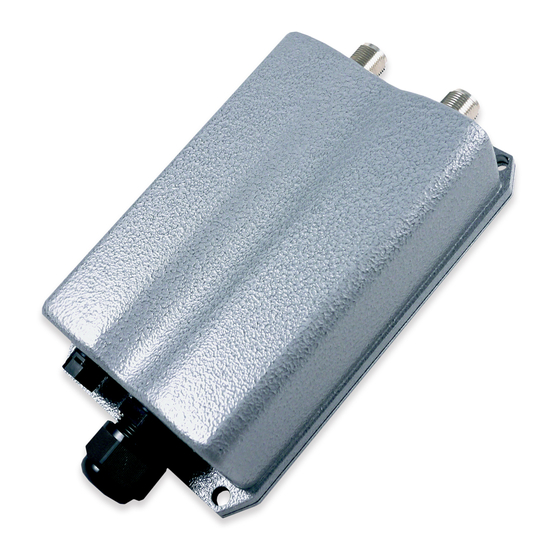
OWL530 Outdoor AP/Bridge/CPE ENGLISH System Overview OWL530 Ventilation Valve Due to extreme weather conditions, water vapor in the OWL530 may condense. The valve allows ventilation to prevent moisture buildup within the OWL530. Ground Connector For connecting the ground wire. PoE Connector For connecting to the Power Sourcing Equipment (PSE). -
Page 7: Hardware Installation
Connect one end of an Ethernet cable to the PSE (POWER & DATA OUT) to the PSE and one end to the OWL530. Inserting the RJ45 connector to the OWL530 Unscrew the cap on the PoE Port (C) - 3 -... - Page 8 Quick Installation Guide OWL530 Outdoor AP/Bridge/CPE ENGLISH Insert the RJ45 cable through the outer opening of cap (C) Insert the RJ45 connector and wrap (A) around the Ethernet cable through the slit between the connector and cap (C) Wrap (B) around (A) through the slit on (B)
- Page 9 Note: pre-installed and secured. Mounting the OWL530 The diameter of poles mountable by the OWL530 mounting kit is from 40mm ~ 60mm Step 1. Screw nuts onto the U-shaped bolts and insert bolts through the split washers. - 5 -...
- Page 10 OWL530 Outdoor AP/Bridge/CPE ENGLISH Step 2. Align the front of OWL530 with the pole and insert the U-shaped bolts into the 4 holes on the corners of the OWL530. Step 3. Secure the OWL530 by screwing on the nuts after the inserting the washers for all four corners.
-
Page 11: Getting Started
To access the Web Management Interface, connect the administrator PC to the Uplink port of OWL530 via an Ethernet cable. Then, set a static IP address on the same subnet mask as OWL530 in TCP/IP of your PC, such as the following example: IP Address: 192.168.1.100... - Page 12 Outdoor AP/Bridge/CPE ENGLISH Step 4: Login Success After a successful login to OWL530, a System Overview page of web management interface will appear, Step 4: Logout To logout, simply click on the Logout button at the upper right hand corner of the interface.
-
Page 13: Common Settings
Ensure the Operating Mode is currently in AP mode. Click on the Status button and then select the System Overview tab. The Operating Mode is at the System section on the System Overview page. - 9 - Copyright © 4IPNET, INC. All rights reserved. - Page 14 Enter a new password in the New Password field with a length of up to 32 characters, and retype it in the Re-enter New Password field. Click SAVE to save the changes. - 10 - Copyright © 4IPNET, INC. All rights reserved.
- Page 15 Click on the System button and then select the Network Interface tab. Click the Static radio button and enter the related information in the fields marked with red asterisks. Click SAVE to save the settings. - 11 - Copyright © 4IPNET, INC. All rights reserved.
- Page 16 2.4GHz for the band, 802.11g+802.11n for the protocol and 6 for the channel. Admin should be aware of Dynamic Frequency Selection (DFS) mandated on some channels of the 5GHz band. When an OWL530 detects interference, this mechanism will limit the ability to broadcast the SSID on one of the channels listed below: ...
- Page 17 Configure VAP (Virtual Access Point) Profile Settings VAP Configuration Page (VAP-1 shown) OWL530 supports up to 16 virtual APs (VAPs) per RF Card. Configure VAP profile settings: Select the VAP Config tab to configure the settings of the desired VAP.
- Page 18 Quick Installation Guide OWL530 Outdoor AP/Bridge/CPE ENGLISH Virtual AP Overview Page - 14 - Copyright © 4IPNET, INC. All rights reserved.
- Page 19 Step 5: Configure WDS (Wireless Distribution System) Settings (Optional) To extend the wireless coverage, OWL530 supports up to 8 WDS links per RF card for connecting wirelessly to other WDS-capable APs, or peer APs. By default, all WDS profiles are disabled.
- Page 20 After it reboot finished, ensure the Operating Mode is currently in CPE mode. Click on the Status button and then select the System Overview tab. The Operating Mode is at the System section on the System Overview page. - 16 - Copyright © 4IPNET, INC. All rights reserved.
- Page 21 Change Admin Account Password Enter a new password in the New Password field and retype it in the Re-enter New Password field. Click SAVE to save the changes. - 17 - Copyright © 4IPNET, INC. All rights reserved.
- Page 22 Select the desired channel to scan will save the time for scanning. Click Scan Again if the APs to be associated with are not listed on the Scan Result list. - 18 - Copyright © 4IPNET, INC. All rights reserved.
- Page 23 Enter the information required in the configuration box. Information to be entered must be exactly the same as configured in this selected AP. Click Connect to start the connection. - 19 - Copyright © 4IPNET, INC. All rights reserved.
- Page 24 Quick Installation Guide OWL530 Outdoor AP/Bridge/CPE ENGLISH Check CPE connection status: After finishing configuration, the Radio Status shall be reflected on the System Overview page. - 20 - Copyright © 4IPNET, INC. All rights reserved.
- Page 25 Quick Installation Guide OWL530 Outdoor AP/Bridge/CPE ENGLISH Step 6: Network Interface Configuration - 21 - Copyright © 4IPNET, INC. All rights reserved.
- Page 26 Congratulations! The CPE mode is now successfully configured. After OWL530's network configuration completes, please remember to change the IP Address of your PC Connection Properties back to its original settings in order to ensure that your PC functions properly in its real network environments.
Need help?
Do you have a question about the OWL530 and is the answer not in the manual?
Questions and answers