Sign In
Upload
Manuals
Brands
CIGWELD Manuals
Welding System
TRANSTIG 200
CIGWELD TRANSTIG 200 Manuals
Manuals and User Guides for CIGWELD TRANSTIG 200. We have
1
CIGWELD TRANSTIG 200 manual available for free PDF download: Service Manual
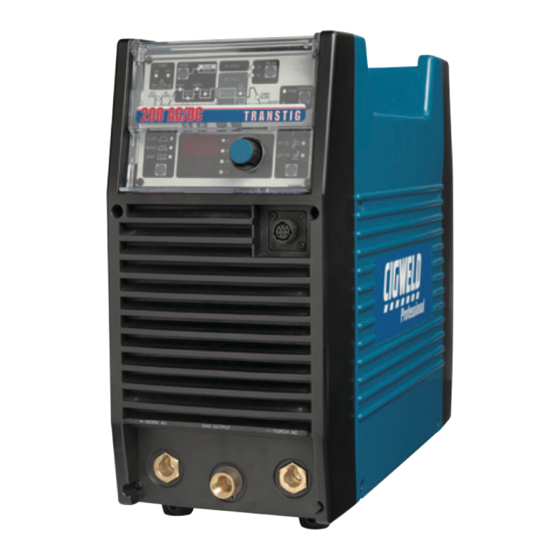
CIGWELD TRANSTIG 200 Service Manual (128 pages)
INVERTER ARC WELDER AC/DC
Brand:
CIGWELD
| Category:
Welding System
| Size: 14 MB
Table of Contents
Table of Contents
4
Arc Welding Safety Instructions and Warnings
9
Arc Welding Hazards
9
Principal Safety Standards
12
Declaration of Conformity
13
Introduction
15
How to Use this Manual
15
Equipment Identification
15
Receipt of Equipment
15
Symbol Chart
16
Description
17
Functional Block Diagrams
18
Transporting Methods
18
Parameter Specifications
19
Installation
21
Environment
21
Location
21
Electrical Input Connections
21
Mains Supply Voltage Requirements
22
High Frequency Introduction
23
High Frequency Interference
23
Duty Cycle
24
Operator Controls
25
Transtig 200 AC/DC Controls
25
Weld Process Selection for Transtig 200 AC/DC
27
Weld Parameter Descriptions for Transtig 200 AC/DC
28
Weld Parameters for Transtig 200 AC/DC
30
Power Source Features
31
Set-Up for Smaw (Stick) and Gtaw (Tig)
33
Sequence of Operation
35
Stick Welding
36
AC or DC HF TIG Welding
36
Slope Mode Sequence
37
Slope Mode with Repeat Sequence
37
Pulse Controls
38
Section 7
39
Basic Tig Welding Guide
39
Explanation of "Fluttery Arc" When AC TIG Welding on Aluminum
39
Electrode Polarity
40
Tungsten Electrode Current Ranges
40
Tungsten Electrode Types
40
Guide for Selecting Filler Wire Diameter
41
Shielding Gas Selection
41
TIG Welding Parameters for Low Carbon & Low Alloy Steel Pipe
41
Welding Parameters for Aluminum
42
Welding Parameters for Steel
42
Section 8
43
Basic Arc Welding Guide
43
Electrode Polarity
43
Effects of Stick Welding Various Materials
43
Section 9
45
Routine Maintenance
45
Section 10
47
Basic Troubleshooting
47
TIG Welding Problems
47
Stick Welding Problems
50
Power Source Problems
53
Power Source Error Codes
55
Power Source Error Codes (Con't)
56
Section 11
57
Voltage Reduction Device (Vrd)
57
VRD Specification
57
VRD Maintenance
57
Section 12
59
Advanced Trouble Shooting
59
Introduction
59
System-Level Fault Isolation
59
Opening the Enclosure
59
Verification and Remedy to the Indicated Error Codes
61
E01 "Over-Temperature at the Primary Side
61
E02 "Over-Temperature at the Secondary Side
62
E03 "Primary Over-Current Failure
62
E04 "Torch Cable Failure
62
E11 "Main Supply over Voltage
63
E12 "Main Supply under Voltage
63
E81 "Abnormal Input Voltage
63
E82 "Rated Voltage Selection Circuit Abnormality
63
E83 "Abnormalities in Mains Supply Voltage Detection
63
E85 "Pre-Charge Abnormality
64
E94 "Thermistor Malfunction
64
E99 "Initial Power Receiving
64
Verification and Remedy to Failures Without Indication Codes
64
Cooling Fan (FAN1) Failure" (Fan Is Not Rotating.)
64
Gas Valve Failure" (no Gas Flow through Unit)
65
No Weld Output
65
Operating Panel Failure
66
High Frequency Output Failure
66
Fault Isolation Tests
67
Preparation
67
Verification of the Power Input Circuitry
67
Verification of the AC Input Voltage Using an AC Voltmeter
67
Verification of Power Supply Voltage
68
Verification of the Cooling Fan, FAN1, Drive Circuitry
69
Verification of the Gas Valve, SOL1, Drive Circuitry
70
Verification of the Primary Diode (D1)
70
Verification of the Secondary Diode (D2, D4, D5)
71
Verification of the Primary IGBT (Q1-Q12)
71
Verification of the Secondary IGBT (Q13)
72
Verification of No-Load Voltage (OCV)
72
Maintenance
75
Maintenance List
75
Service Tools
79
Tools and Parts
79
Notes of Disassembly and Assembly
79
Replacement Procedure
80
Pcb1 (Wk-5477)
80
Pcb2 (Wk-5596)
81
Pcb3 (Wk-5548), Pcb5 (Wk-5551)
83
Pcb4 (Wk-4819)
84
Pcb6 (Wk-5549)
84
Pcb7 (Wk-5550)
85
Pcb8 (Wk-5479) (Igbt (Q1~Q6))
85
Pcb9 (Wk-5479) (Igbt (Q7~Q12))
86
Pcb10 (Wk-5527)
87
Pcb11 (Wk-5528)
87
PCB12 (WK-5615), Transformer (T1), Current Trans (CT2)
89
Pcb13 (Wk-5569)
92
Pcb16 (Wk-5499)
93
Pcb14 (Wk-5570)
93
Pcb17 (Wk-4917)
94
Pcb18 (Wk-5861)
95
Discharge Resistor (R3)
96
Current Limiting Resistor (R4, R5)
97
Resistor on High Frequency Unit (R6)
98
Coupling Coil (CC1)
98
Reactor (FCH1)
99
Primary Thermistor (TH1)
100
Secondary Thermistor (TH2)
100
Cooling Fan (FAN1)
101
Solenoid Valve (SOL1)
102
Main ON/OFF Switch (S1)
103
Remote Connector (CON1)
103
High Freguency Unit (HF.UNIT1)
105
Hall C.T. (HCT1)
105
Primary Diode (D1)
106
Secondary Diode (D2, D4, D5)
107
Secondary IGBT (Q13) (PCB15 (WK-3367))
108
Reactor (L101)
109
Earth Inductance (L103)
109
Parts List
114
Appendix 1: Parts List
115
Appendix 2: Connection Wiring Guide
116
Appendix 2: Connection Wiring Guide
117
Appendix 3 Diode Testing Basics
118
Appendix 4: Transtig 200 Ac/DC Accessories
119
Appendix 5: Transtig 200 Ac/DC Interconnection Diagram
120
Cigweld Limited Warranty
123
Warranty Schedule - January 2008
127
Global Customer Service Contact Information
127
Advertisement
Advertisement
Related Products
Cigweld 200DC
Cigweld 200AC
CIGWELD 200 Pi Transtig
CIGWELD TRANSTIG 200 AC/DC
CIGWELD WELDSKILL 200HF
CIGWELD 255
CIGWELD 250i Transmig
CIGWELD 2RT wire feeder
CIGWELD 2RT TRANSMIG
CIGWELD Transcmig 250se
CIGWELD Categories
Welding System
Wire Feeders
Inverter
More CIGWELD Manuals
Login
Sign In
OR
Sign in with Facebook
Sign in with Google
Upload manual
Upload from disk
Upload from URL