
Related Manuals for MasterCraft 055-5530-8


Summary of Contents for MasterCraft 055-5530-8
-
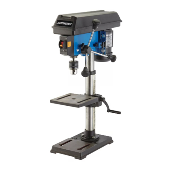
Page 1: Drill Press
055-5530-8 DRILL PRESS IMPORTANT: INSTRUCTION Please read this manual carefully before using this drill MANUAL press and save it for reference. - Page 2 TABLE OF CONTENTS Quick Start Guide Specifications Safety Guidelines 6-13 Know Your Drill Press 14-16 Assembly Instructions 17-28 Operating Instructions 29-32 Maintenance Troubleshooting Exploded View Parts List 36-37 Warranty NOTE: If any parts are missing or damaged, or if you have any questions, please call our toll-free helpline at 1-800-689-9928 SAVE THESE INSTRUCTIONS This manual contains important safety and operating instructions.
- Page 3 055-5530-8 | contact us 1-800-689-9928 SPECIFICATIONS • Place the column tube (2) on the base (1), align the column support holes with the Motor 120 V, 60 Hz, 4.1A base holes. Pulley speeds 620, 1150, 1630, 2180, 3070 RPM (no load) •...
- Page 4 055-5530-8 | contact us 1-800-689-9928 SAFETY GUIDELINES • Wear proper apparel. Do not wear lose clothing, gloves, neckties, rings, bracelets or other jewelry that may get caught in moving parts. Nonslip footwear is recommended. Wear protective hair covering This manual contains information that relates to PROTECTING PERSONAL SAFETY and PREVENTING to contain long hair.
- Page 5 055-5530-8 | contact us 1-800-689-9928 11. Protection: Eyes, hands, ears and body. Never leave tool running unattended. Turn power off. Don’t leave tool until it comes to a complete • stop. TO AVOID BEING PULLED INTO THE SPINNING TOOL—...
- Page 6 055-5530-8 | contact us 1-800-689-9928 12. Use only accessories designed for this drill press to avoid serious injury from thrown, USE SAFETY GOGGLES AND EAR PROTECTION: broken parts or workpieces. ALWAYS WEAR EYE PROTECTION THAT CONFORMS WITH CUL REQUIREMENTS. FLYING a.
- Page 7 055-5530-8 | contact us 1-800-689-9928 Recommended size for extension cords Do not modify the plug provided. If it will not fit the outlet, have the proper outlet installed by a qualified electrician. AMPERAGE RATING OF THE TOOL TOTAL LENGTH OF THE EXTENSION CORD...
- Page 8 055-5530-8 | contact us 1-800-689-9928 Description Description Pulley housing cover Motor pulley LED worklight switch Belt Feed return spring and cover Feed handle LED worklight Motor Chuck Tension lock knob Column Depth tension knob Table Rack Chuck key...
- Page 9 055-5530-8 | contact us 1-800-689-9928 Motor: PACKAGE CONTENTS Your drill press is equipped with an industrial-duty induction motor for long-lasting, smooth performance. Description Illustration Table: The table of your drill press rotates 360˚ and bevels up to 45˚ for angle drilling.
- Page 10 055-5530-8 | contact us 1-800-689-9928 TOOLS NEEDED FOR ASSEMBLY Description Illustration Rack collar Star-head screwdriver Framing square Flat washers M8 Wrench Hammer Spring washers M8 Block of wood Ruler UNPACKING Bolts M8x25 Do not use this product if any parts of the package contents are already assembled to your product when you unpack it.
- Page 11 055-5530-8 | contact us 1-800-689-9928 BASE TO COLUMN (Fig. 2) • Insert the table support crank handle (7) into the worm gear shaft on the side of the table support (8). Make • Set the base (1) on the floor.
- Page 12 055-5530-8 | contact us 1-800-689-9928 INSTALL THE CHUCK (Fig. 10) LED WORKLIGHT BATTERIES (Fig. 8) • Inspect and clean the taper hole in the chuck (1) and • Turn off the worklight. the spindle (2). Remove all grease, coatings, and •...
- Page 13 055-5530-8 | contact us 1-800-689-9928 SPINDLE SPEEDS (Fig. 14) OPERATING ADJUSTMENTS This drill press offers five spindle speeds from 620 to 3070 RPM. The highest speed is obtained when the belt INSTALL THE BELT (Fig. 12) is positioned on the largest motor pulley step and the smallest spindle pulley stop.
- Page 14 055-5530-8 | contact us 1-800-689-9928 DRILLING DEPTH (Fig. 19) ADJUSTMENTS TO RAISE OR LOWER TABLE (Fig. 16) • To stop the drill at a specific depth for consistent and • Raise or lower the table by loosening the column lock...
- Page 15 055-5530-8 | contact us 1-800-689-9928 ON/OFF SWITCH (Fig. 23) ANGULAR PLAY OF THE SPINDLE (Fig. 21) • To turn the drill press On, insert the safety key (1) into Move the spindle to the lowest downward position and hold the switch housing (2).
- Page 16 055-5530-8 | contact us 1-800-689-9928 DEPTH SCALE METHOD (Fig. 27) DRILLING A HOLE Use a centre punch or sharp nail to dent the workpiece where you want the hole. With the switch Off, bring • With the switch (1) Off, turn the feed handle (2) until the drill bit down to the workpiece, lining it up with the hole location.
- Page 17 055-5530-8 | contact us 1-800-689-9928 GENERAL MAINTENANCE DRILLING WOOD Frequently blow out or vacuum sawdust or metal chips that accumulate in and on the motor, pulley housing, • Brad point bits are preferred. Metal piercing twist bits may be used on wood.
- Page 18 055-5530-8 | contact us 1-800-689-9928 TROUBLESHOOTING PROBLEM Possible Causes Solution Will not start. • Power cord is not plugged in. • Plug in. • Fuse or circuit breaker ripped. • Replace fuse or reset tripped circuit 40 75 breaker.
- Page 19 055-5530-8 | contact us 1-800-689-9928 PARTS LIST Description Description Description Description Base Gear pad Axis Hex nut Column support Earthing pin Axis sleeve Motor pulley Flat washer Spring washer Spring ring Belt Spring washer Screw Pulley Motor Bolt...
- Page 20 055-5530-8 | contact us 1-800-689-9928 3-Year Limited Warranty This Mastercraft product is guaranteed for a period of 3 years from the date of original retail purchase against defects in workmanship and materials, except for the following component: Component A: Accessories, which are guaranteed for a period of 1-year from the date of original retail purchase against defects in workmanship and materials.
Need help?
Do you have a question about the 055-5530-8 and is the answer not in the manual?
Questions and answers