
Related Manuals for MasterCraft 055-5511-4


Summary of Contents for MasterCraft 055-5511-4
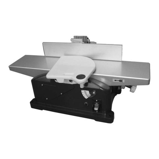
- Page 1 6-1/8" JOINTER Item No.:055-5511-4 Instruction Manual Toll-Free Helpline 1-800-689-9928...
-
Page 2: Table Of Contents
Electrical information............. Know your jointer..............Assembly and adjustments........... Operating instructions............VII. Maintenance................. VIII. Warranty................Parts list................I. Specifications Model: 055-5511-4 Motor: 120 V 60 Hz 10A Speed: 10,000 RPM (no load) Blade: 6 1/8" Max. cutting depth: 1/8" Fence tilts: 45–135°... -
Page 3: General Safety Guidelines
If you have any questions relative to a particular application, DO NOT use the machine until you have first contacted Mastercraft to determine if it can or ®... - Page 4 II. General safety guidelines (continued) or expose them to rain. Keep work area well lighted. 6. KEEP CHILDREN AWAY. All visitors should be kept safe distance from work area. 7. MAKE WORKSHOP CHILD PROOF with padlocks, master switches, or by removing starter keys.
- Page 5 II. General safety guidelines (continued) 20. CHECK DAMAGED PARTS. Before further use of the tool, a guard or other part that is damaged should be carefully checked to determine that it will operate properly and perform its intended function - check for alignment of moving parts, binding of moving parts, breakage of parts, mounting, and any other conditions that may affect its operation.
- Page 6 II. General safety guidelines (continued) 10. KEEP ARMS, HANDS, AND FINGERS away from the cutterhead to prevent severe injury. 11. HOLD THE WORKPIECE FIRMLY against the table and fence. Loss of control of the workpiece can cause kickback and result in serious injury. 12.
- Page 7 II. General safety guidelines (continued) - Do not perform jointing operations on material shorter than a dimension equal to the cutter head length plus 2" (5 cm), ), narrower than 3/4" (19 mm), or less than 1/4" (6 mm) in thick. - Do not perform planing operations on material shorter than a dimension equal to the cutter head length plus 2"...
-
Page 8: Electrical Information
III. Electrical information POWER CONNECTIONS A separate electrical circuit should be used for your machines. This circuit should not be less than #12 wire and should be protected with a 20 A time lag fuse. If an extension cord is used, use only 3-wire extension cords which have 3-prong grounding type plugs and matching receptacle which will accept the machine’s plug. - Page 9 III. Electrical information (continued) CAUTION: Use proper extension cords. Make sure your extension cord is in good condition and is a 3-wire extension cord which has a 3-prong grounding type plug and matching receptacle which will accept the machine’s plug. When using an extension cord, be sure to use one heavy enough to carry the current of the machine.
-
Page 10: Know Your Jointer
IV. Know your jointer Fence Clamping lever chamfering angle Out-feed table Fence mounting bracket Cutterhead guard 10 Mounting hole Scale for planing depth 11 Fence sliding bracket In-feed table 12 Clamping lever planing width Planing depth adjustment knob 13 Dust extraction outlet On/Off switch 14 Push blocks... -
Page 11: Assembly And Adjustments
V. Assembly and adjustments UNPACKING Carefully unpack the bench jointer and all of its parts, and compare them against the list below. Do not discard the carton or any packaging until the bench jointer is completely assembled. Remove the protective coating from all unpainted surfaces. This coating may be removed with a soft cloth moistened with kerosene (do not use acetone, gasoline or lacquer thinner for this purpose). - Page 12 V. Assembly and adjustments (continued) FUNCTIONAL DESCRIPTION JOINTING OPERATION Fig. 1 Jointing cuts or edge jointing are made to square an edge of a workpiece. The workpiece is positioned on the jointer with the narrow edge of the workpiece on the infeed table and the major flat surface of the workpiece against the fence, as shown in Fig.
- Page 13 V. Assembly and adjustments (continued) MOUNTING FENCE (Fig. 4-9) Fig. 4 - Assemble the fence mounting bracket (A) Fig. 4 to the jointer base using the two M6 x 35 mm hexagonal screws (B) (Fig. 4). - Slide groove of fence (C) (Fig. 5) over hexagonal screws (D) lying in the sliding fence bracket.
- Page 14 V. Assembly and adjustments (continued) MOUNTING CUTTERHEAD GUARD Fig. 10 (Fig. 10-11) - Loosen the two socket head cap screws M6 x 25 mm (A) (Fig. 10) on the base and remove them. - Align the holes on the cutterhead guard (B) and base, then put an M6 flat washer (C) (Fig.
- Page 15 V. Assembly and adjustments (continued) FENCE ADJUSTMENTS (Fig. 14-20) Fig. 14 The fence can be moved across the table and can be tilted up to 45 , as follow: - To move the fence across the table, loosen clamping lever (A) (Fig. 14). Slide the fence to the desired position on the table and tighten the clamping lever (A).
- Page 16 V. Assembly and adjustments (continued) REPLACING CUTTERHEAD Fig. 21 (Fig. 21-23) CAUTION: Before replacing the cutterhead, always unplug the machine. The springs (A) can fall out of the cylinder when replacing or adjusting the cutterhead. Always make sure that the springs remain in the same position.
- Page 17 V. Assembly and adjustments (continued) ADJUSTING CUTTERHEAD Fig. 24 (Fig. 23-27) CAUTION: Before replacing the cutterhead, always unplug the machine. - Remove cutterhead guard. - Turn planing depth adjustment knob (H) (Fig. 24) closewise until the pointer points to 1/8”. - Adjust the bolts (C) (Fig.
-
Page 18: Operating Instructions
VI. Operating instructions STARTING AND STOPPING JOINTER Fig. 28 (Fig. 28) The on/off switch (A) Fig. 28 is located on the front of the jointer cabinet. To turn the machine “ON”, move the switch (A) up to the “ON” position. To turn the machine “OFF”, move the switch (A) down to the “OFF”... - Page 19 VI. Operating instructions (continued) The following directions will give the beginner a start on jointer operations. Use scrap pieces of lumber to check the settings and to get the feel of the operations before attempting regular work. NOTE: The cutterheads on the jointer will not wear evenly by feeding the wood through the same spot on the table every time.
- Page 20 VI. Operating instructions (continued) PLANING WARPED PIECES Fig. 34 If the wood to be planed is dished or warped, take light cuts until the surface is flat. Avoid forcing such material down against the table; excessive pressure will spring it while passing the cutterheads, and it will spring back and remain curved after the cut is completed.
- Page 21 VI. Operating instructions (continued) DUST EXTRACTION (Fig. 38) Fig. 38 The dust extraction outlet together with an external vacuum cleaner takes care of the dust extraction of the working surface. - If necessary, connect an adapter to the connection (A) (Fig. 38). - Connect a vacuum cleaner to the machine.
-
Page 22: Maintenance
VII. Maintenance WARNING: Make sure that the jointer is turned off and unplugged from power source before maintenace operations. KEEP MACHINE CLEAN Periodically blow out all air passages with dry compressed air. All plastic parts should be cleaned with a soft damp cloth. Never use solvents to clean plastic parts. Solvents could possibly dissolve or otherwise damage the material. -
Page 23: Warranty
VIII. Warranty 3-Year Limited Warranty This Mastercraft product is guaranteed for a period of 3 years from the date of original retail purchase against defects in workmanship and materials, except for the following component: Component A: Accessories, which are guaranteed for a period of 1year from the date of original retail purchase against defects in workmanship and materials. -
Page 24: Parts List
IX. Parts list MASTERCRAFT Jointer 055-5511-4 ® When servicing your Mastercraft Jointer, use Mastercraft replacement parts only. Use of any ® ® other parts may cause product damage. Any and all servicing of the Jointer should be performed by a qualified service technician. - Page 25 IX. Parts list (continued) Description Description Guard cover Motor housing Guard Inductance Ball bearing Ring Stator core Spring Self tapping bolt Buffer block Rotor Bolt Ball bearing Open ring Motor cover Adjustment tool Fixed base Wrench Bolt Hex key Bolt Screw M8 x 45 Screw M6 x 35 Carbon brush Flat washer M6...
- Page 26 Imported by Mastercraft Canada Toronto, Canada M4S 2B8...
Need help?
Do you have a question about the 055-5511-4 and is the answer not in the manual?
Questions and answers
comment ajuster la table d'entree du 55-5511-8 jointer mastercraft. elle n'est pas un niveau avec la table de sortie Input table is not align with output table
To adjust the infeed table of the MasterCraft jointer model 055-5511-4 (note: there is no mention of model 055-5511-8 in the context) to align with the outfeed table:
1. Use the planing depth adjustment knob.
2. Turn the knob clockwise to lower the infeed table.
3. Turn the knob counterclockwise to raise the infeed table.
4. Adjust until the infeed table aligns with the outfeed table for the desired depth of cut.
A dual English/Metric scale and pointer indicate the current depth setting.
This answer is automatically generated