
Related Manuals for MasterCraft 055-5509-2


Summary of Contents for MasterCraft 055-5509-2
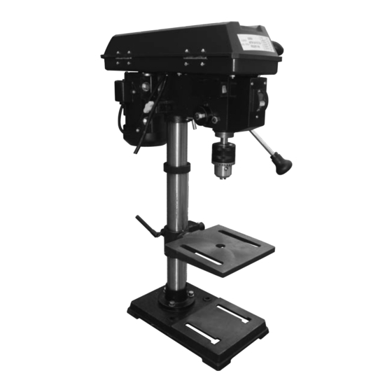
- Page 1 10" DRILL PRESS Item No.: 055-5509-2 Instruction Manual Toll-Free Helpline 1-800-689-9928...
-
Page 2: Table Of Contents
Assembly and adjustments........... Operating instructions............VII. Maintenance................VIII. Troubleshooting..............Warranty................Parts list................. I. Specifications Model: 055-5509-2 Motor: 120 V 60 Hz 4.1 A Spindle travel: 50 mm Column diameter: 50 mm Max. drilling capacity: 5/8" diameter Pulley speeds: 620, 1150, 1630, 2180, 3070 RPM (no load) Table size: 7 1/4 x 7 1/4"... -
Page 3: General Safety Guidelines
II. General safety guidelines WARNING! READ ALL INSTRUCTIONS Failure to follow the safety rules listed below and other basic safety precautions may result in serious personal injury. Work Area KEEP CHILDREN AWAY Do not let visitors contact tool or extension cord. All visitors should be kept safe distance from work area. - Page 4 Service Centre, Authorized Service Station or other competent ® repair service. WARNING! Use only Mastercraft® replacement parts; any others may create a hazard. WARNING! The use of any other accessories not specified in the current Mastercraft catalog ® may create a hazard.
- Page 5 II. General safety guidelines (continued) AVOID GASEOUS AREAS Do not operate electric tools in a gaseous or explosive atmosphere. Motors in these tools normally spark, and this may result in a dangerous condition. MAINTAIN TOOLS WITH CARE Keep tools sharp and clean for best and safest performance. Follow instructions for lubricating and changing accessories.
- Page 6 II. General safety guidelines (continued) a. If any part of your drill press is missing, malfunctioning, has been damaged or broken, such as the motor switch, or other operating control, a safety device or the power cord, cease operating immediately until the particular part is properly repaired or replaced. b.
- Page 7 II. General safety guidelines (continued) b. Drum sanders must NEVER be operated on this drill press at a speed greater than the speed rating of the drum sander. c. Do not install or use any drill bit that exceeds 7" in length or extends 6" below the chuck jaws.
- Page 8 II. General safety guidelines (continued) WARNING! Do not allow familiarity (gained from frequent use of your drill press) to become commonplace. Always remember that a careless fraction of a second is sufficient to inflict severe injury. WARNING! WEAR EYE PROTECTION! The operation of any power tool can result in foreign objects being thrown into the eyes, which can result in severe eye damage.
- Page 9 II. General safety guidelines (continued) ALWAYS WEAR EYE PROTECTION THAT CONFORMS WITH CSA REQUIREMENTS. FLYING DEBRIS can cause permanent eye damage. Prescription eyeglasses are not a replacement for proper eye protection. WARNING! EXPOSURE TO EXCESSIVE NOISE LEVELS CAN RESULT IN PERMANENT HEARING LOSS.
-
Page 10: Electrical Information
III. Electrical information MOTOR SPECIFICATIONS In the event of a malfunction or breakdown, grounding provides a path of least resistance for electric current to reduce the risk of electric shock. This tool is equipped with an electric cord having an equipment-grounding conductor and a grounding plug. The plug must be plugged into a matching outlet that is properly installed and grounded in accordance with all local codes and ordinances. - Page 11 III. Electrical information (continued) Always use proper extension cord. The use of any extension cord will cause some loss of power. To keep this to a minimum and to prevent overheating and motor burn-out, use the table below to determine the minimum wire size (A.W.G.) extension cord. Use only 3-wire extension cords which have 3-prong grounding type plugs and 3-pole receptacles which accept the tool’s plug.
-
Page 12: Know Your Drill Press
IV. Know your drill press Pulley housing cover 16 Belt Laser switch 17 Spindle pulley Locking screws 18 Depth scale Power cord 19 Pointer Rack collar 20 Quill Support lock handle 21 Table Bevel scale 22 Column support On/off switch 23 Feed handle Feed return spring and cover 24 Motor... -
Page 13: Assembly And Adjustments
WARNING: To reduce the risk of injury, never connect plug to power source outlet until all assembly steps are complete and until you have read and understood the entire owner’s manual. MASTERCRAFT Drill Press is shipped complete in one box. ®... - Page 14 V. Assembly and adjustments (continued) ASSEMBLY AND ADJUSTMENTS Fig. 1 WARNING: To reduce the risk of injury, never connect plug to power source outlet until all assembly steps are completed. TOOLS NEEDED FOR ASSEMBLY • Adjustable wrench • Screwdriver • Hammer and block of wood BASE TO COLUMN (Fig.
- Page 15 V. Assembly and adjustments (continued) DRILL PRESS HEAD TO COLUMN (Fig. 5) Fig. 5 1. Lift the drill press head assembly (1) carefully and place the mounting hole of the drill press head onto the top of the column (2). Make sure the head is seated properly on the column.
- Page 16 V. Assembly and adjustments (continued) INSTALL THE CHUCK (Fig. 9) Fig. 9 1. Inspect and clean the taper hole in the chuck (1) and the spindle (2). Remove all grease, coatings, and particles from the chuck and spindle surfaces with a clean cloth.
- Page 17 V. Assembly and adjustments (continued) OPERATING ADJUSTMENTS WARNING: To reduce the risk of injury: • Turn switch “OFF” and remove plug from the power source before making adjustments. • Follow instructions carefully and wear eye protection to avoid thrown parts due to spring release.
- Page 18 V. Assembly and adjustments (continued) SPINDLE SPEEDS (Fig. 13) This drill press offers 5 spindle speeds from 620 to 3070 RPM. The highest speed is obtained when the belt is positioned on the largest motor pulley step and the smallest spindle pulley stop. Fig.
- Page 19 V. Assembly and adjustments (continued) TABLE ADJUSTMENTS TO RAISE OR Fig. 15 LOWER (Fig. 15) 1. Raise or lower the table by loosening the column lock handle (1) and turning the crank handle (2) until the table is at the desired height. 2.
- Page 20 V. Assembly and adjustments (continued) DRILLING DEPTH (Fig. 18) Fig. 18 1. To stop the drill at a specific depth for consistent and repetitive drilling, loosen the depth scale lock (1) located on the depth scale hub (2). 2. Turn the hub until the pointer (3) is aligned to the desired depth on the scale.
- Page 21 V. Assembly and adjustments (continued) INSTALL DRILL BITS (Fig. 21) Fig. 21 1. Place the chuck key (1) into the side keyhole of the chuck (2), meshing the gear teeth (3). 2. Turn the chuck key counterclockwise to open the chuck jaws (4).
- Page 22 V. Assembly and adjustments (continued) ADJUST THE LASER LINE (Fig. 22-23) Fig. 23 1. Place a workpiece on the table. 2. Turn the laser switch (1) to the ON position. 3. Lower the drill bit to meet the workpiece (2). The laser line should cross where the drill meets the workpiece.
-
Page 23: Operating Instructions
VI. Operating instructions ON/OFF SWITCH (Fig. 24) Fig. 24 1. To turn the drill press ON, insert the safety key (1) into the switch housing (2). As a safety feature, the switch cannot be turned ON without the key. 2. Flip the switch upward to the ON position. 3. - Page 24 VI. Operating instructions (continued) DRILLING A HOLE Fig. 26 Use a centre punch or sharp nail to dent the workpiece where you want the hole. With the switch OFF, bring the drill bit down to the workpiece, lining it up with the hole location.
- Page 25 VI. Operating instructions (continued) DEPTH SCALE METHOD (Fig. 27) Fig. 27 1. With the switch (1) OFF, turn the feed handle (2) until the drill bit tip (3) slightly touches the top of the workpiece (4). 2. Hold the feed handles in that position. 3.
- Page 26 VI. Operating instructions (continued) under the workpiece. FEEDING THE BIT • Pull down on the feed handles with only enough force to allow the drill bit to cut. • Feeding too rapidly might stall the motor, cause the belt to slip, damage the workpiece, or break the drill bit.
-
Page 27: Maintenance
To avoid shock or fire hazard, if the power cord is worn, cut or damaged in any way, have it replaced immediately. WARNING: All repairs, electrical or mechanical, should be attempted only by trained repairmen. Use only MASTERCRAFT replacement parts; any other may create a hazard. ®... -
Page 28: Troubleshooting
VIII. Troubleshooting This section describes problems and malfunctions that you should be able to resolve yourself. DANGER: Many accidents happen particularly in connection with problems and faults. Therefore please note: 1. Always unplug before servicing. 2. Check that all safety devices are operational again after each servicing. SYMPTOM POSSIBLE CAUSE(S) CORRECTIVE ACTION... -
Page 29: Warranty
IX. Warranty 3-Year Limited Warranty This Mastercraft product is guaranteed for a period of 3 years from the date of original retail purchase against defects in workmanship and materials, except for the following component: Component A: Accessories, which are guaranteed for a period of 1 year from the date of original retail purchase against defects in workmanship and materials. -
Page 30: Parts List
X. Parts list MASTERCRAFT Drill Press 055-5509-2 ® When servicing your Mastercraft Drill Press, use Mastercraft replacement parts only. Use of ® ® any other parts may cause product damage. Any and all servicing of the Drill Press should be performed by a qualified service technician. - Page 31 X. Parts list (continued) Description Description Connected axis Handle Bolt Base for feed handle Base board Rail for feed handle Flat washer Ball for feed handle Spring washer Rack collar Hexagon nut Rack Motor pulley Chuck key Belt Allen wrench Motor Allen wrench Worm pin...
- Page 32 72 73 (77) (78) (36) (43) (43) (40) (67) (68) (66) (73) (69) (59) (41) (26) 39 38 37 42 41 40 46 45 (61) (13) Imported by Mastercraft Canada Toronto, Canada M4S 2B8...
Need help?
Do you have a question about the 055-5509-2 and is the answer not in the manual?
Questions and answers
Bonjour ! Est-ce que vous vendez un axe pour le model 55-5509-2 ? Le mien est croche. C'est le No: 16 sur la photo.
Yes, the parts list for MasterCraft model 055-5509-2 includes an "Axis" (part number 16), which refers to an axle. This indicates that a replacement axle is available for this model.
This answer is automatically generated
Drill press 55-5509-2 - chuck comes loose from Axis/spindle
To fix a loose chuck on the MasterCraft drill press model 055-5509-2, follow these steps:
1. Ensure the jaws are fully recessed into the chuck.
2. Do not use a metal hammer directly to drive the chuck into the spindle.
3. Secure the chuck properly by pressing it firmly into place.
If the chuck is still loose, you may need to remove it and reinstall it properly:
1. Lower the chuck to its lowest position using the feed handles.
2. Use a ball joint separator above the chuck and lightly tap it with a hammer to release it from the spindle.
3. Reinstall the chuck by aligning it correctly and pressing it back into place securely.
Always ensure the drill press is turned off and unplugged before making adjustments.
This answer is automatically generated
I need the chuck
What is the key size for the 055-5509-2 drill press? Do you carry these?