Table of Contents
Advertisement
Available languages
Available languages
Quick Links
Advertisement
Chapters
Table of Contents

Related Manuals for Videotec HOV


Summary of Contents for Videotec HOV
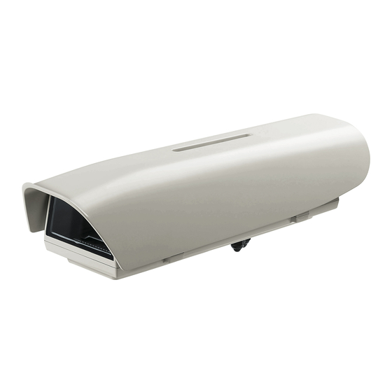
- Page 1 Side opening aluminium camera housing English - Instructions manual Italiano - Manuale di istruzioni Français - Manuel d’instructions Deutsch - Bedienungslanleitung Русский - Руководство по эксплуатации...
- Page 3 ENGLISH Side-opening aluminium camera housing English - Instruction manual...
-
Page 5: Table Of Contents
Contents E N G L I S H 1 About this manual ......................4 1.1 Typographical conventions ..........................4 2 Notes on copyright and information on trademarks ..........4 3 Safety rules........................4 4 Identification ........................5 4.1 Product description and type designation..................... 5 4.2 Product marking .............................. -
Page 6: About This Manual
1 About this manual 3 Safety rules Read all the documentation supplied carefully before CAUTION! Device installation and installing and using this unit. Keep the manual in a maintaining must be performed by convenient place for future reference. specialist technical staff only. 1.1 Typographical conventions CAUTION! The electrical system to which the unit is connected must be equipped... -
Page 7: Identification
• This device was designed to be permanently • A power disconnect device must be included secured and connected on a building or on a in the electrical installation, and it must be very suitable structure. The device must be permanently quickly recognizable and operated if needed. -
Page 8: Preparing The Product For Use
5 Preparing the product for 5.3 Safely disposing of packaging material The packaging material can all be recycled. The Any change that is not expressly approved installer technician will be responsible for separating by the manufacturer will invalidate the the material for disposal, and in any case for guarantee. -
Page 9: Installation
6 Installation 6.2 How to install the camera 6.1 How to open the housing Power supply can be provided by the board supplied with the product. Make sure the Loosen the 2 screws on the side, turn the cover and voltage values are appropriate. -
Page 10: Board Description
6.3 Board description 6.4 Connection of the power supply line The board may appear different to that illustrated. CAUTION! The type of cable used must be compatible with the planned use. Comply Depending on the product version, the with the national regulations in force on board may not be equipped with all electrical installation. -
Page 11: Installation Of The Version With Double Filter For Air Renewal
6.5 Installation of the version 6.6 Installation of the version with double filter for air renewal with wiper Open the housing as described in the relative chapter During installation pay attention to the (6.1 How to open the housing, page 7). orientation of the air inlet filter fins. -
Page 12: Accessories
7 Accessories 7.2 Camera power supply 7.2.1 Camera power supply installation For further details on configuration and use, refer to the relative manual. Not usable in housings with wiper device installed. 7.1 Heater Pay attention to the voltage used to power 7.1.1 Heater installation the circuit. -
Page 13: Blower
7.3 Blower Open the housing as described in the relative chapter (6.1 How to open the housing, page 7). 7.3.1 Blower installation Fix the support bracket (02) using the screw (01). Place the power supply (03) on the support bracket. Not usable in versions with double filter for Secure it all with the screws (04) and the corner fixing air renewal and wiper. -
Page 14: Instructions For Normal Operation
8 Instructions for normal 10 Disposal of waste operation materials Do not use the wiper if the outside This symbol mark and recycle system temperature is below 0°C or in case of ice. are applied only to EU countries and not applied to other countries of the world. -
Page 15: Technical Data
11 Technical data Supply voltage/Current consumption (version with blower and thermostat for models with double filter for air renewal, Ton 35°C±3°C (95°F±5°F), Toff 11.1 General 20°C±3°C (71°F±5°F)): Constructed from aluminium • 12Vdc, 400mA max Sunshield in ABS • 24Vac, 200mA max, 50/60Hz Epoxypolyester powder painting, RAL9002 colour Supply voltage/Current consumption (version with integrated wiper):... -
Page 16: Technical Drawings
12 Technical drawings The dimensions of the drawings are in millimetres. USABLE USABLE AREA AREA A - A B - B R100 Fig. 13 HOV. MNVCHOV32_1702_EN... - Page 18 Email: info@videotec.com Tel. +33 1 60491816 - Fax +33 1 69284736 Email: info.fr@videotec.com Asia Pacific Videotec (HK) Ltd Americas Videotec Security, Inc. Flat 8, 19/F. On Dak Industrial Building, No. 2-6 Wah Sing Street Gateway Industrial Park, 35 Gateway Drive, Suite 100 Kwai Chung, New Territories - Hong Kong Plattsburgh, NY 12901 - U.S.A.
- Page 19 ITALIANO Custodia per telecamera in alluminio ad apertura laterale Italiano - Manuale di istruzioni...
- Page 21 Sommario I T A L I A N O 1 Informazioni sul presente manuale ................4 1.1 Convenzioni tipografiche ............................. 4 2 Note sul copyright e informazioni sui marchi commerciali ........4 3 Norme di sicurezza ......................4 4 Identificazione ....................... 5 4.1 Descrizione e designazione del prodotto .......................
-
Page 22: Informazioni Sul Presente Manuale
1 Informazioni sul presente 3 Norme di sicurezza manuale ATTENZIONE! L'installazione e la manutenzione del dispositivo deve Prima di installare e utilizzare questa unità, leggere essere eseguita solo da personale tecnico attentamente tutta la documentazione fornita. Tenere specializzato. il manuale a portata di mano per consultazioni successive. -
Page 23: Identificazione
• Questo dispositivo è stato progettato per essere • L’impianto elettrico deve essere dotato di un fissato e collegato in maniera permanente sezionatore di rete prontamente riconoscibile e su un edificio o su una struttura adeguata. Il utilizzabile in caso di necessità. dispositivo deve essere fissato e collegato in 4 Identificazione maniera permanente prima di effettuare qualsiasi... -
Page 24: Preparazione Del Prodotto Per L'utilizzo
5 Preparazione del prodotto 5.3 Smaltimento in sicurezza dei materiali di imballaggio per l'utilizzo I materiali d'imballo sono costituiti interamente da Qualsiasi intervento non espressamente materiale riciclabile. Sarà cura del tecnico installatore approvato dal costruttore fa decadere la smaltirli secondo le modalità di raccolta differenziata garanzia. -
Page 25: Installazione
6 Installazione 6.2 Installazione della telecamera 6.1 Apertura della custodia L'alimentazione può essere fornita dalla scheda in dotazione al prodotto. Accertarsi Svitare le 2 viti poste sul fianco, far ruotare tettuccio che i valori di tensione siano adeguati. e corpo superiore attorno all’asse delle cerniere di Aprire la custodia come descritto nel relativo capitolo apertura. -
Page 26: Descrizione Della Scheda
6.3 Descrizione della scheda 6.4 Collegamento della linea di alimentazione L'aspetto della scheda potrebbe differire da quello illlustrato. ATTENZIONE! La tipologia di cavo utilizzata deve essere compatibile con l'impiego La scheda, a seconda della versione del previsto. Attenersi alle regole nazionali in prodotto, potrebbe non essere dotata di vigore riguardanti le installazioni elettriche. -
Page 27: Installazione Della Versione Con Doppio Filtro Per Ricambio Dell'aria
6.5 Installazione della versione 6.6 Installazione della versione con doppio filtro per ricambio con tergicristallo dell'aria Aprire la custodia come descritto nel relativo capitolo (6.1 Apertura della custodia, pagina 7). Durante l'installazione prestare attenzione Individuare il morsetto della scheda tergicristallo. all'orientamento delle alette del filtro di ingresso dell'aria. -
Page 28: Accessori
7 Accessori 7.2 Alimentatore per telecamera 7.2.1 Installazione dell’alimentatore per Per ulteriori dettagli sulla configurazione telecamera e l’utilizzo fare riferimento al manuale del relativo accessorio. Non utilizzabile nelle custodie munite di sistema tergicristallo. 7.1 Riscaldamento Prestare attenzione al valore di tensione 7.1.1 Installazione del riscaldamento utilizzato per alimentare il circuito. -
Page 29: Ventilatore
7.3 Ventilatore Aprire la custodia come descritto nel relativo capitolo (6.1 Apertura della custodia, pagina 7). 7.3.1 Installazione del ventilatore Utilizzando la vite (01) fissare la staffa di appoggio (02). Posizionare l'alimentatore (03) sulla staffa di Non utilizzabile nelle versioni con doppio appoggio. -
Page 30: Istruzioni Di Funzionamento Ordinario
8 Istruzioni di 10 Smaltimento dei rifiuti funzionamento ordinario Questo simbolo e il sistema di riciclaggio sono validi solo nei paesi dell'EU e non Non utilizzare il tergicristallo se la trovano applicazione in altri paesi del temperatura esterna è inferiore a 0°C o in mondo. -
Page 31: Dati Tecnici
11 Dati tecnici Tensione di alimentazione/Corrente assorbita (versione con ventilatore e termostato per modelli con doppio filtro per ricambio dell'aria, Ton 35°C±3°C, 11.1 Generale Toff 20°C±3°C): Costruzione in alluminio • 12Vdc, 400mA max Tettuccio in ABS • 24Vac, 200mA max, 50/60Hz Verniciatura a polveri di epossipoliestere, colore Tensione di alimentazione/Corrente assorbita RAL9002... -
Page 32: Disegni Tecnici
12 Disegni tecnici Le dimensioni dei disegni sono espresse in millimetri. AREA AREA UTILE UTILE A - A B - B R100 Fig. 13 HOV. MNVCHOV32_1702_IT... - Page 34 Email: info@videotec.com Tel. +33 1 60491816 - Fax +33 1 69284736 Email: info.fr@videotec.com Asia Pacific Videotec (HK) Ltd Americas Videotec Security, Inc. Flat 8, 19/F. On Dak Industrial Building, No. 2-6 Wah Sing Street Gateway Industrial Park, 35 Gateway Drive, Suite 100 Kwai Chung, New Territories - Hong Kong Plattsburgh, NY 12901 - U.S.A.
- Page 35 FRANÇAIS Caisson pour caméra en aluminium à ouverture latérale Français - Manuel d’instructions...
- Page 37 Sommaire F R A N Ç A I S 1 À propos de ce mode d’emploi ..................4 1.1 Conventions typographiques ..........................4 2 Notes sur le copyright et informations sur les marques de commerce ..... 4 3 Normes de securité ......................4 4 Identification ........................
-
Page 38: À Propos De Ce Mode D'emploi
1 À propos de ce mode 3 Normes de securité d’emploi ATTENTION! L’installation et l’entretien du dispositif doivent être effectués Avant d'installer et d'utiliser cette unité, lire exclusivement par un personnel technique attentivement toute la documentation fournie. qualifié. Garder le manuel à portée de main pour des consultations successives. -
Page 39: Identification
• Cet appareil est conçu pour être fixé et relié de • L'installation électrique doit être équipée d'un manière permanente sur un bâtiment ou une sectionneur de réseau facile à reconnaître et à structure adéquate. L'appareil doit être fixé et relié utiliser en cas de nécessité. -
Page 40: Préparation Du Produit En Vue De L'utilisation
5 Préparation du produit en 5.3 Élimination sans danger des matériaux d’emballage vue de l’utilisation Le matériel d’emballage est entièrement composé Toute modification non approuvée de matériaux recyclables. Le technicien chargé de expressément par le fabricant entraînera l’installation est tenu de l’éliminer conformément aux l’annulation de la garantie. -
Page 41: Installation
6 Installation 6.2 Installation de la caméra 6.1 Ouverture du caisson L'alimentation peut être dotée de la carte fournie avec le produit fournie. Dévisser les 2 vis placées sur le côté, faire tourner le S'assurer que les valeurs de tension soient toit pare-soleil et le corps supérieur autour de l’axe appropriées. -
Page 42: Description De La Carte
6.3 Description de la carte 6.4 Connexion de la ligne d'alimentation L'aspect de la carte pourrait être différer de celui qui est illustré. ATTENTION! Le type de câble utilisé doit être compatible avec l'usage prévu. La carte, selon la version du produit, Respectez les règles nationales en vigueur pourrait ne pas être munie de toutes les en matière d'installations électriques. -
Page 43: Installation De La Version Avec Double Filtre Pour Le Changement D'air
6.5 Installation de la version avec 6.6 Installation de la version avec double filtre pour le changement essuie-glace d'air Ouvrir le caisson selon la description dans le chapitre correspondant (6.1 Ouverture du caisson, page 7). Durant l'installation prêter l'installation à Identifier la borne de la carte de l'essui-glace. l'orientation des ailettes du filtre d'entrée de l'air. -
Page 44: Accessoires
7 Accessoires 7.2 Alimentation pour caméra 7.2.1 Installation de l’alimentateur pour Pour de plus amples informations sur la caméra configuration et l'utilisation, consulter le manuel de l'accessoire correspondant. Pas utilisable pour les caissons équipés de système essuie-glace installé. 7.1 Chauffage Il faut faire attention au valeur de tension 7.1.1 Installation du chauffage utilisée en alimentant le circuit. -
Page 45: Ventilateur
7.3 Ventilateur Ouvrir le caisson selon la description dans le chapitre correspondant (6.1 Ouverture du caisson, page 7). 7.3.1 Installation du ventilateur En utilisant la vis (01) fixer la bride de soutien (02). Positionner l'alimentateur (03) sur la bride de soutien. Pas utilisable dans les versions avec double Fixer le tout avec les vis (04) et la bride de fixation filtre pour le changement d'air et essuie-... -
Page 46: Instructions De Fonctionnement Courant
8 Instructions de 10 Élimination des déchets fonctionnement courant Ce symbole et le système de recyclage ne sont appliqués que dans les pays UE et non Ne pas utiliser l’essuie-glace avec dans les autres pays du monde. température extérieure inférieure à 0°C ou Votre produit est conçu et fabriqué... -
Page 47: Données Techniques
11 Données techniques Tension d’alimentation/Courant absorbé (version avec ventilateur et thermostat avec double filtre pour le renouvellement de l’air, Ton 35°C±3°C, Toff 11.1 Généralités 20°C±3°C): Construction en aluminium • 12Vdc, 400mA max Double toit en ABS • 24Vac, 200mA max, 50/60Hz Vernissage avec poudres époxypolyester, couleur Tension d’alimentation/Courant absorbé... -
Page 48: Dessins Techniques
12 Dessins techniques Les dimensions des dessins sont exprimées en millimètres. SURFACE SURFACE UTILE UTILE A - A B - B R100 Fig. 13 HOV. MNVCHOV32_1702_FR... - Page 50 Email: info@videotec.com Tel. +33 1 60491816 - Fax +33 1 69284736 Email: info.fr@videotec.com Asia Pacific Videotec (HK) Ltd Americas Videotec Security, Inc. Flat 8, 19/F. On Dak Industrial Building, No. 2-6 Wah Sing Street Gateway Industrial Park, 35 Gateway Drive, Suite 100 Kwai Chung, New Territories - Hong Kong Plattsburgh, NY 12901 - U.S.A.
- Page 51 DEUTSCH Aluminiumgehäuse mit Seitenöffnung Deutsch - Bedienungsanleitung...
- Page 53 Inhaltsverzeichnis D E U T S C H 1 Allgemeines ........................4 1.1 Schreibweisen ................................4 2 Anmerkungen zum Copyright und Informationen zu den Handelsmarken ..... 4 3 Sicherheitsnormen ......................4 4 Identifizierung ....................... 5 4.1 Beschreibung und Bezeichnung des Produktes ................... 5 4.2 Kennzeichnung des Produkts..........................
-
Page 54: Allgemeines
1 Allgemeines 3 Sicherheitsnormen Vor Installation und Anwendung der Einheit ist die ACHTUNG! Die Installation und Wartung gesamte gelieferte Dokumentation aufmerksam zu der Vorrichtung ist technischen Fachleuten lesen. Zum späteren Nachschlagen das Handbuch in vorbehalten. Reichweite aufbewahren. 1.1 Schreibweisen ACHTUNG! Die elektrische Anlage, an der die Einheit angeschlossen ist, muss mit einem automatischen zweipoligen GEFAHR! -
Page 55: Identifizierung
• Die Einrichtung ist für die dauerhafte Befestigung • Die elektrische Anlage muss mit einem und Verbindung in ein Gebäude oder eine andere Netztrennschalter versehen sein, der im Bedarfsfall geeignete Struktur konzipiert. Vor jeder Operation sofort erkannt und gebraucht werden kann. muss die Einrichtung dauerhaft befestigt und 4 Identifizierung verbunden werden. -
Page 56: Vorbereitung Des Produktes Auf Den Gebrauch
5 Vorbereitung des 5.3 Sichere Entsorgung der Verpackungsmaterialien Produktes auf den Gebrauch Die Verpackungsmaterialien sind vollständig Jede vom Hersteller nicht ausdrücklich wiederverwertbar. Es ist Sache des genehmigte Veränderung führt zum Verfall Installationstechnikers, sie getrennt, auf jeden der Gewährleistungsrechte. Fall aber nach den geltenden Vorschriften des Anwendungslandes zu entsorgen. -
Page 57: Installation
6 Installation 6.2 Installation der Kamera 6.1 Öffnung des Schutzgehause Die Stromversorgung muss über die Karte erfolgen, die im Lieferumfang des Die beiden an der Flanke befindlichen Schrauben Geräts enthalten ist. Prüfen, dass die abdrehen, nun die Haube und den oberen Korpus um Spannungswerte angemessen sind. -
Page 58: Beschreibung Der Karte
6.3 Beschreibung der Karte 6.4 Anschluss der Stromversorgung Die Abbildung kann von der tatsächlichen Karte abweichen. ACHTUNG! Der verwendete Kabeltyp muss mit dem vorgesehenen Einsatz kompatibel Je nach Geräteausführung verfügt die Karte sein. An die geltenden nationalen möglicherweise nicht über alle Funktionen. Vorschriften in Bezug auf elektrische Installationen halten. -
Page 59: Installation Der Version Mit Doppelfilter Für Den Luftaustausch
6.5 Installation der Version 6.6 Installation der Ausführung mit Doppelfilter für den mit Scheibenwischer Luftaustausch Das Gehäuse nach der Erläuterung im zugehörigen Kapitel öffnen (6.1 Öffnung des Schutzgehause, Seite Während der Installation auf die Ausrichtung der Luftklappen am Die Klemme der Wischerplatine ausfindig machen. Lufteinlassfilter achten. -
Page 60: Zubehör
7 Zubehör 7.2 Kameranetzteil 7.2.1 Installation des Netzteil für Für weitere Details zur Konfiguration und Kamera zum Gebrauch beachten Sie bitte das Handbuch des entsprechenden Geräts. Nicht anwendbar in Gehäusen mit installiertem Scheibenwischer. 7.1 Heizung Wenn der Schaltkreis gespeist wird, muß 7.1.1 Installation der Heizung auf Versorgungsspannungswert geachtet Das Gehäuse nach der Erläuterung im zugehörigen... -
Page 61: Lüfter
7.3 Lüfter Das Gehäuse nach der Erläuterung im zugehörigen Kapitel öffnen (6.1 Öffnung des Schutzgehause, Seite 7.3.1 Installation des Lüfters Mit der Schraube (01) den Haltebügel (02) befestigen. Nicht anwendbar in den Ausführungen mit Das Netzteil (03) auf den Haltebügel stellen. Alles Doppelfilter und Scheibenwischer für den mit den Schrauben (04) und der Winkelkonsole (05) Luftaustausch. -
Page 62: Anleitung Für Den Normalen Betrieb
8 Anleitung für den 10 Müllentsorgungsstellen normalen Betrieb Dieses Symbol und das entsprechende Recycling-System gelten nur für EULänder Der Scheibenwischer ist bei und finden in den anderen Ländern der Aussentemperaturen unter 0°C oder bei Welt keine Anwendung. Frost nicht zu betätigen. Ihr Produkt wurde entworfen und hergestellt 9 Reinigung aus qualitativ hochwertigen Materialien und... -
Page 63: Technische Daten
11 Technische Daten Versorgungsspannung/Stromaufnahme (Version mit Lüfter und Thermostat mit Doppelfilter für Luftwechsel, Ton 35°C±3°C, Toff 20°C±3°C): 11.1 Allgemeines • 12Vdc, 400mA max Aus Aluminium • 24Vac, 200mA max, 50/60Hz Sonnenschutzdach aus ABS Versorgungsspannung/Stromaufnahme (Version mit Pulverlackierung mit Epoxydpolyester, Farbe RAL9002 integriertem Scheibenwischer): Externe Schrauben aus rostfreiem Stahl •... -
Page 64: Technische Zeichnungen
12 Technische Zeichnungen Die Abmessungen der Zeichnungen sind in Millimeter angegeben. NUTZ- NUTZFLÄCHE FLÄCHE A - A B - B R100 Abb. 13 HOV. MNVCHOV32_1702_DE... - Page 66 Email: info@videotec.com Tel. +33 1 60491816 - Fax +33 1 69284736 Email: info.fr@videotec.com Asia Pacific Videotec (HK) Ltd Americas Videotec Security, Inc. Flat 8, 19/F. On Dak Industrial Building, No. 2-6 Wah Sing Street Gateway Industrial Park, 35 Gateway Drive, Suite 100 Kwai Chung, New Territories - Hong Kong Plattsburgh, NY 12901 - U.S.A.
- Page 67 РУССКИЙ Откидной алюминиевый кожух камеры Русский - Руководство по эксплуатации...
- Page 69 Комплект оборудования Р У С С К И Й 1 О настоящем руководстве ..................4 1.1 Типографские условные обозначения ......................4 2 Примечания в отношении авторского права и информация о торговых марках ..........................4 3 Правила техники безопасности ................4 4 Обозначение...
-
Page 70: О Настоящем Руководстве
1 О настоящем 3 Правила техники руководстве безопасности Внимательно ознакомьтесь со всей ПРЕДУПРЕЖДЕНИЕ! Установка документацией, входящей в комплект поставки, и обслуживание устройства перед тем как приступить к установке и должны осуществляться только эксплуатации данного оборудования. Всегда специализированным персоналом. держите руководство под рукой, чтобы им можно было... -
Page 71: Обозначение
• Это устройство разработано для подключения и • Электрическая система оснащается установки на здании или подходящей выключателем питания, который можно легко конструкции. Устройство следует надежно найти и использовать в случае необходимости. закрепить и подключить перед выполнением 4 Обозначение каких-либо работ. •... -
Page 72: Подготовка Устройства К Использованию
5 Подготовка устройства к 5.3 Безопасная утилизация упаковочных материалов использованию Упаковочные материалы могут подвергаться Любое изменение, которое выполняется переработке. Технический специалист без разрешения, явным образом установщика отвечает за сортировку материалов предоставленного производителем, для переработки, а также за соблюдение аннулирует гарантию. требований... -
Page 73: Монтаж
6 Монтаж 6.2 Установка камеры 6.1 Как открыть кожух Питание может обеспечиваться платой, предоставляемой вместе с устройством Ослабьте 2 винта сбоку и поверните крышку Убедитесь в правильности значений и верхнюю половину корпуса в направлении напряжения. открывания петли. Откройте кожух, следуя указаниям в соответствующем... -
Page 74: Описание Платы
6.3 Описание платы 6.4 Подключение линии питания Плата может отличаться от той, что указана на рисунке. ПРЕДУПРЕЖДЕНИЕ! Тип используемого кабеля должен быть совместимым с Плата, в зависимости от версии предполагаемым видом использования. устройства, может не обладать всеми Соблюдайте действующие в вашей функциями. -
Page 75: Установка Модели С Двойным Фильтром Для Воздухообмена
6.5 Установка модели с 6.6 Установка модели со двойным фильтром для стеклоочистителем воздухообмена Откройте кожух, следуя указаниям в соответствующем разделе (6.1 Как открыть кожух, Во время установки обратите внимание страница 7). на направление ребер впускного Определите клемму платы стеклоочистителя. воздушного фильтра. Рис. -
Page 76: Комплектующие
7 Комплектующие 7.2 Питание камеры 7.2.1 Установка источника питания Дополнительная информация по камеры конфигурации и использованию представлена в соответствующем Не используется в кожухах, оснащенных руководстве. стеклоочистителем. 7.1 Нагреватель Обратите внимание на значение используемого напряжения при подаче 7.1.1 Установка нагревателя напряжения на контур. В зависимости от Откройте... -
Page 77: Вентилятор
7.3 Вентилятор Откройте кожух, следуя указаниям в соответствующем разделе (6.1 Как открыть кожух, 7.3.1 Установка вентилятора страница 7). С помощью винта (01) закрепите опорный Не используется в моделях с двойным кронштейн (02). Расположите источник питания фильтром для воздухообмена и (03) на опорном кронштейне. Прикрепите все стеклоочистителем. -
Page 78: Инструкции По Работе В Нормальном Режиме
8 Инструкции по работе в 10 Утилизация отходов нормальном режиме Соответствующий символ и система переработки отходов используются Не используйте стеклоочиститель только в странах ЕС и не применяются в при температуре ниже 0°C или при других странах мира. обледенении. Ваше устройство разработано и произведено 9 Очистка... -
Page 79: Технические Характеристики
11 Технические Напряжение сети питания/Потребляемый ток (модель с нагнетательным вентилятором и характеристики термостатом для моделей с двойным фильтром для воздухообмена, Ton 35°C±3°C, Toff 20°C±3°C): 11.1 Общие сведения • 12Vdc, 400mA max • 24Vac, 200mA max, 50/60Hz Модель без дополнительного оборудования Напряжение... -
Page 80: Технические Чертежи
12 Технические чертежи Размеры на чертежах указаны в миллиметрах. ПОЛЕЗНАЯ ПОЛЕЗНАЯ ОБЛАСТЬ ОБЛАСТЬ A - A B - B R100 Рис. 13 HOV. MNVCHOV32_1702_RU... -
Page 82: Mnvchov32_1702_De
Email: info@videotec.com Тел.: +33 1 60491816 - факс: +33 1 69284736 Email: info.fr@videotec.com Азиатско-Тихоокеанский регион Videotec (HK) Ltd. Americas Videotec Security, Inc. Flat 8, 19/F. On Dak Industrial Building, No. 2-6 Wah Sing Street Gateway Industrial Park, 35 Gateway Drive, Suite 100 Kwai Chung, New Territories - Hong Kong Plattsburgh, NY 12901 - U.S.A. - Page 84 Email: info@videotec.com Tel. +33 1 60491816 - Fax +33 1 69284736 Email: info.fr@videotec.com Asia Pacific Videotec (HK) Ltd Americas Videotec Security, Inc. Flat 8, 19/F. On Dak Industrial Building, No. 2-6 Wah Sing Street Gateway Industrial Park, 35 Gateway Drive, Suite 100 Kwai Chung, New Territories - Hong Kong Plattsburgh, NY 12901 - U.S.A.
Need help?
Do you have a question about the HOV and is the answer not in the manual?
Questions and answers