Table of Contents
Advertisement
Advertisement
Table of Contents

Related Manuals for McIntosh MX130


Summary of Contents for McIntosh MX130
- Page 1 MX130 A/V TUNER CONTROL CENTER...
- Page 3 MX130 A/V TUNER CONTROL CENTER...
- Page 4 1. Read all instructions - Read the safety and operating instructions before operating the instrument. IMPORTANT 2. Retain Instructions - Retain the safety and operating instructions for future reference. 3. Heed warnings - Adhere to warnings and operating instructions. SAFETY 4.
- Page 5 1 8 . Grounding or Polarization - Do not defeat the inherent design features of the polarized plug. Non- IMPORTANT polarized line cord adaptors will defeat the safety provided by the polarized AC plug. 19. CAUTION: TO PREVENT ELECTRICAL SHOCK DO NOT USE THIS (POLARIZED) PLUG SAFETY WITH AN EXTENSION CORD, RECEPTACLE OR OTHER OUTLET UNLESS THE BLADES CAN INSTRUCTIONS...
- Page 6 Your Mclntosh Authorized Service Agency can expedite repairs when you provide them with the Service Contract. SERVICE CONTRACT TABLE OF INTRODUCTION 6, 7 CONTENTS HOW TO INSTALL THE MX130 HOME THEATER AUDIO CHANNEL CONFIGURATION WITH ® DOLBY PRO LOGIC™ AND HOME THX AUDIO 8, 9 FRONT PANEL CONTROLS, SWITCHES AND PUSHBUTTONS .9, 10, 11, 12, 13, 14, 15...
- Page 7 TAKE ADVANTAGE OF 3 YEARS OF CONTRACT SERVICE. . . MclNTOSH FILL IN THE APPLICATION NOW. THREE YEAR SERVICE Your MX130 Audio/Video Tuner Control Center will give you many years of satisfactory perform- CONTRACT ance. If you have any questions, please contact, Mclntosh Laboratory Inc. 2 Chambers Street...
- Page 8 Ease of maintenance is another Mclntosh design philosophy that contributes to the long useful operating life of all Mclntosh products. The MX130, A/V Tuner Control Center is a full featured remote control center tor a com- plete Mclntosh Home Theater System. It provides six audio channels with the added features of video switching.
- Page 9 DOLBY SURROUND, PRO LOGIC and the Double-D Symbol are trademarks of Dolby Licensing Laboratory. Home THX" Audio is a trademark of Lucasfilm Ltd. The MX130 can be placed upright on a table or shelf, standing on its own plastic feet. It HOW TO also can be installed in an optional Mclntosh L74 equipment cabinet.
- Page 10 Dolby Surround encoding is also used for MTS and satellite broadcasts as well as other AND HOME audio-only program sources such as compact discs. Use the MX130 CINEMA 1 mode with ® its Dolby Pro Logic processing to enjoy listening to these other program sources.
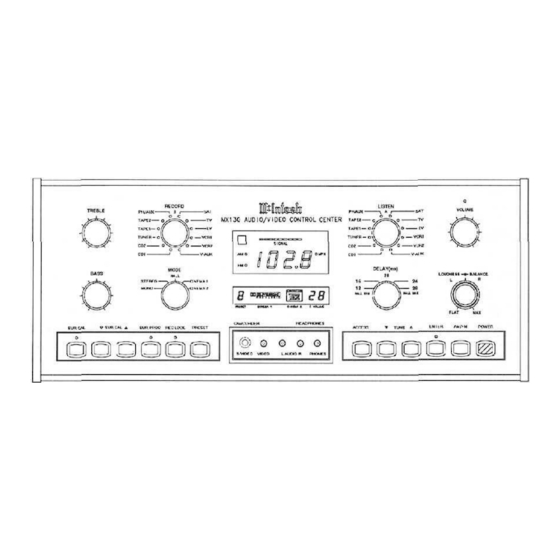
- Page 11 The MX130 can be remotely controlled. Most of the operating functions performed FRONT at the front panel, also can be done by the MX130 Hand Held Remote Controller. The PANEL following information refers only to the front panel. Another section of this manual CONTROLS explains the functions and operation of the MX130 Hand Held Remote Controller.
- Page 12 LEFT Surround and RIGHT Surround outputs. The Left, Right and Center signals of 80Hz and lower are also combined by the MX130 and fed to the SUBWOOFer Output. The Subwoofer output is always ON in CINEMA 1 mode, and is not affected by the rear panel SUB WOOF Switch.
- Page 13 Dolby surround encoding is also used for MTS and satellite broadcasts as well as CONTROLS, other audio-only program sources such as compact discs. Use the MX130 CINEMA 1 SWITCHES mode with its Dolby Pro Logic processing to enjoy listening to these other program sources.
- Page 14 1. PRESET indicates the number of the AM or FM station preset that has been selected. CONTROLS, SWITCHES 2. The Dolby Pro Logic indicator lights when the MX130 is switched to CINEMA 1 or CINEMA 2 mode. 3. The Home THX Audio indicator lights when the X130 is in CINEMA 2 Mode, with the PUSHBUTTONS THX-M Module installed.
- Page 15 BALANCE Control is neutral. SYS CAL (SYStem CALibrate) Allows the volume level of all six channels to be accurately set using the built-in MX130 noise generator. Calibration includes individual channel volume adjustment or trimming which may be required due to room geometry or differences in amplifiers or speakers. The calibra- tion can be done by automatic or manual switching of the noise generator to each channel, depending on the setting of the MX130 rear panel SURROUND CALIBRATE switch.
- Page 16 HALL, CINEMA 1 and CINEMA 2. The numbers indicate the time delay in milliseconds when the MX130 is in CINEMA 1 or CINEMA 2 operating modes. The HALL mode of opera- tion has slightly longer delay times. Refer to the chart below for the exact delay times for each mode.
- Page 17 AM AND FM 3. Press the ENTER pushbutton. The LED above the pushbutton will turn on. STATION The MX130 will remain in the preset ENTER mode for 10 seconds to allow the follow- PRESETS ing preset programming steps. 4. Push the PRESET pushbutton and scroll to the PRESET number desired for that par- ticular station.
- Page 18 0 to 9 to control the desired relays on the HC-1. 5. Press SYS OFF to turn the entire MX130 system off from either Area "A" or Area "B". In Area "B", pressing POWER turns on only Area "B" after the SYS OFF is activated.
- Page 19 14. Press ACC (ACCessory) OFF or ACC ON to control the AC Power of an accessory com- ponent that is being used in combination with an RCT-1 Remote Control Translator. HOW TO INSTALL BATTERIES IN THE MX130 HAND HELD REMOTE CONTROLLER Slide open the battery compartment. Insert two type AA batteries into the compartment, making sure to observe the battery polarities Indicated in the battery compartment.
- Page 20 CONNECTIONS ALL SIGNALS FED TO THE SIX UNBALANCED OUTPUTS ALSO APPEAR AT THE MX130 REAR PANEL 6 CHANNEL OUTPUT CONNECTOR AND ARE FED THROUGH AN OPTIONAL 25 CONDUCTOR SUBMINIATURE "D" MALE-TO-FEMALE COMPUTER TYPE CABLE TO A MATCHING CONNECTOR ON A MclNTOSH MC7106 SIX CHANNEL POWER AMPLIFIER.
- Page 21 When an external signal processor is properly connected, the program signals will feed to the processor from the MX130 PROCESSOR TO jacks, and return to the MX130 REAR PANEL at the PROCESSOR FROM jacks. AND HOW Connect a pair of cables from the external processor Outputs to the MX 130 PROCESSOR TO MAKE FROM jacks.
- Page 22 Left and Right Front signals, balanced cables can eliminate the possibility of hum pickup. If cable lengths between the MX130 and the power amplifiers are one meter or less, you may find high quality unbalanced cables to be satisfactory. Balanced Jack Pin Configuration: Pin 1.
- Page 23 TV: Connect a coaxial cable from the MX 130 TV coaxial output to the coaxial antenna in- HOW TO MAKE put of a TV receiver being used as a monitor. Whenever the MX130 is turned OFF, the RF CONNECTIONS signals feed from the ANT/CABLE connector directly to the TV connector and the TV set for normal TV reception.
- Page 24 Refer to the manual section "MclNTOSH HOME THEATER SURROUND SOUND VOLUME LEVEL CALIBRATION" for detailed information on the surround level calibra- REAR PANEL tion procedure. 24. AREA B OUTput, (L and R) HOW TO MAKE Connect a pair of cables from the AREA "B", L (Left) and R (Right) OUTputs to the inputs CONNECTIONS of the dedicated power amplifier that is connected to the loudspeakers in Area "B".
- Page 25 The SUM DATA port is used for connecting to the Mclntosh Model RCT-1 Remote Control Translator. Any IR signal transmitted to a CR39 sensor results in data signals at this port. The RCT-1 is a learning device that will allow the MX130 to remotely control most major brands of accessory components.
- Page 26 Remote Control System. With a CR10 connected, as many as four additional remote areas can be controlled. CD2, TUNER, TAPE 1, TAPE 2 and PH/AUX can be used by the CR10. All signals selected by the MX130 LISTEN, Area "A" switch are fed to the VIDEO inputs on the CR10.
- Page 27 If you are using the optional Mclntosh THX-M module in your MX130 for Home THX Audio processing, the requirements are even more specific. Mclntosh has introduced the HT Home Theater line of loudspeakers specifically designed for home theater use.
- Page 28 MclNTOSH Home THX Audio specifies that a subwoofer be used. The MX130 includes the required HOME THEATER circuits to feed the correct bass signals of 80Hz and lower to the output that feeds the sub- woofer power amplifier.
- Page 29 MclNTOSH HOME THEATER HOOKUP...
- Page 30 CALIBRATION 1. Set the MODE Switch to CINEMA 1. 2. Set the MX130 VOLUME control to a level indication of 30% ± 10%. 3. Set the rear panel SURROUND CALIBRATE Switch to MANUAL. Press the SYS CAL surround level calibration pushbutton. This starts the built-in noise generator and feeds it first to the LEFT FRONT channel to begin the level calibration pro- cess.
- Page 31 A convenient method for surround volume level calibration in the Automatic chan- nel cycling mode, is to use the UP ( ) or DOWN ( ) pushbuttons on the MX130 Hand Held Remote Controller and operate it from a position located in the listening area at seated ear height.
- Page 32 (For future reference, list the final calibration trim numbers in the space provided in this manual. If the MX130 AC power cord is disconnected from the AC power line, or AC power is interrupted, the backup power supply will turn off and calibration memory will be lost. The calibration process must then be repeated.)
- Page 33 Do this by pressing the UP ( ) or DOWN ( ) SURROUND pushbutton on the MX130 Hand Held Remote Controller until you are satisfied with the results. These changes will remain as long as the MX130 continues to operate.
- Page 34 FREQUENCY RESPONSE SPECIFICATIONS MONO and STEREO MODES (LEFT, CENTER and RIGHT FRONT Channels), +0, -0.5dB from 20Hz to 20,000Hz HALL MODE LEFT, CENTER and RIGHT SURROUND Channels, +0, -0.5dB from 20Hz to 20,000Hz LEFT and RIGHT SURROUND channels, +0, -3dB from 100Hz to 7000Hz DOLBY PRO LOGIC MODE LEFT, CENTER and RIGHT FRONT Channels, + 0.5dB from 30Hz to 16,000Hz LEFT and RIGHT SURROUND Channels, ±1dB from 100Hz to 6300Hz, -3dB at 7000Hz...
- Page 35 DOLBY PRO-LOGIC and THX MODES SPECIFICATIONS All outputs greater than 70dB below reference level. MAXIMUM INPUT SIGNAL PHONO: 60mV. HIGH LEVEL: 5V, MONO and STEREO; 2.1V, HALL, DOLBY PRO LOGIC and THX. INPUT IMPEDANCE PHONO: 47K ohms and 65pF capacitance HIGH LEVEL: 22K ohms VOLTAGE GAIN PHONO to TAPE: 40dB...
- Page 36 IMAGE RESPONSE SPECIFICATIONS 80dB. RF INTERMODULATION 65dB. STEREO SEPARATION 45dB at 100Hz. 50dB at 1000Hz. 35dB at 10,000Hz. SCA REJECTION 65dB (AM SECTION) SENSITIVITY 20uV External Antenna Input, 50 ohm generator. SIGNAL TO NOISE 50dB at 30% modulation. 60dB at 100% modulation. HARMONIC DISTORTION 0.5% Maximum at 50% modulation.
- Page 37 CUSTOM INSTALLATION DRAWING...
- Page 38 The letters and numbers correspond to the paragraphs on pages 8 through 21.
- Page 40 04001600 BE022003...
Need help?
Do you have a question about the MX130 and is the answer not in the manual?
Questions and answers