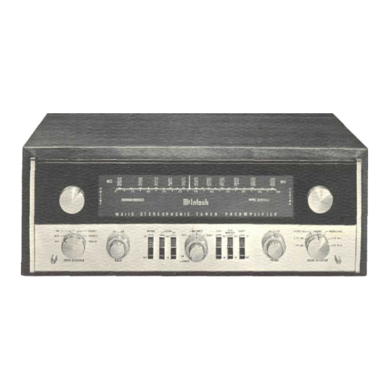
McIntosh MX 110 Owner's Manual
Stereo tuner preamplifier
Hide thumbs
Also See for MX 110:
- Service manual (23 pages) ,
- Owner's manual (23 pages) ,
- Manual (43 pages)

Related Manuals for McIntosh MX 110


Summary of Contents for McIntosh MX 110
-
Page 1: Table Of Contents
STEREO TUNER MX 11O PREAMPLIFIER GENERAL DESCRIPTION TECHNICAL DESCRIPTION FRONT PANEL FACILITIES INSTALLATION CONNECTING AC Connections AC Power Connection Input Connections Output Connections Antenna Connections OPERATING INSTRUCTIONS CONTENTS Balancing a Stereo System Adjusting Phase Balancing Loudness Between Program Sources Adjusting the Balance Control After the System has been Balanced Adjusting for Special Effects Listening to Monophonic FM Program... -
Page 3: General Description
MX110 TUNER PREAMPLIFIER GENERAL DESCRIPTION The MX110 combines in one unit an ex- ness. These adjusting controls are located on tremely low-distortion preamplifier with a the top of the MX110 behind the front panel. highly sensitive FM multiplex stereo tuner. By releasing the PANLOC buttons on the Every desirable feature of a tuner and a pre- front panel, you can slide the MX110 out of... - Page 4 MULTIPLEX DECODER The multiplex decoder uses a special 38KC components in the output and insure Mclntosh developed detecting circuit. One of low distortion. A three-section sharp cut off filter rejects the advantages of this circuit is the elimina- SCA interference and reduces susceptibility tion of the critical adjustments necessary with commonly used matrixing methods.
- Page 5 MECHANICAL SPECIFICATIONS Finish Dimensions Anodized gold and black (front panel). Chassis: 16 inches wide; 5 inches high; 13 inches deep including connectors. Installation Front Panel: 16 inches wide; 5 inches high. Convenient, professional PANLOC. Knob Clearance: 1½ inches. Weight Chassis: 27½ pounds. Shipping Weight: 36 pounds.
- Page 6 tion. H.F. Cutoff Filter: 2 positions: Flat, or Controls Input Selector: Total 6 positions: AUX, 5KC cutoff. (20db per octave.) L.F. Cutoff MPX, FM, PHONO 1, PHONO 2, TAPE Filter: 2 positions: Flat, or 50 cycles cutoff. (20db per octave.) HEADS.
-
Page 7: Front Panel Facilities
Selenium Silicon Rectifiers High and Low Voltage Supply Diodes DC Filament Supply 1 MA113 Transistor-Indicator Light Switch FRONT PANEL INFORMATION Figure 1. MX110 Front Panel. signal while rejecting noise pulses of equal DIAL SCALES The MX110 has two scales. The 88 to 108 intensity. - Page 8 MX110. To properly VOLUME operate the MX 110, consult the section titled OPERATING INSTRUCTIONS on page 4. PHONO 1—The PHONO 1 position of the INPUT SELECTOR connects the jacks on the back panel marked PH-1 MAG. and PH-1 XTAL through the MX110.
- Page 9 pendently. Turning clockwise increases bass loudness. Turning them counterclockwise decreases bass loudness. TREBLE Figure 6. MODE SELECTOR. Figures. TREBLE Control. 4. STEREO—The MODE SELECTOR in the The TREBLE control is a dual control. The STEREO position connects the left input to two parts are concentric.
- Page 10 The POWER ON-OFF switch is the center volume control to a loudness compensated or small knob of this dual control. The MX 110 control. Use the LOUD IN to listen at low is off when the POWER switch is turned to the...
- Page 11 PHASE TAPE MONITOR Figure 15. PHASE Switch. Figure 14 TAPE MONITOR Switch. The PHASE switch corrects for loud- The TAPE MONITOR switch compares the speaker or program phasing. Placing this recorded tape with the program source. switch in the 180° position reverses phase in When the TAPE MONITOR switch is in the the left channel.
-
Page 12: Installation
INSTALLATION The MX 110 can be installed in conventional The MX 110 installation should allow l3½ inches behind the front panel which includes furniture cabinets, custom built installations or professional relay racks. If the unit is to be 1½ inches for connectors. The desirable... -
Page 13: Input Connections
tape comparison is controlled by the TAPE INPUT CONNECTIONS MONITOR switch. The MX110 provides six separate pro- The input program connections should be gram inputs controlled by the INPUT SELEC- TOR switch. One input for tape monitor or made in accordance with Table 1. Figure 18. -
Page 14: Output Connections
panel controls: VOLUME control, BASS con- OUTPUT CONNECTIONS trols, LF and HF filter switches, BALANCE There are three sets of outputs on the left control, LOUD switch, TAPE MONITOR switch, half of the back panel. (See Figure 19.) One PHASE switch, TREBLE controls, and MODE pair is marked MAIN. -
Page 15: Operating Instructions
OUTDOOR ANTENNA IMPORTANT: An outdoor antenna is recommended for BEFORE TURNING THE MX110 ON, optimum performance in all areas. In fringe CHECK TO SEE THAT ALL TUBES ARE (outlying) areas, best results will be obtained FIRMLY SEATED IN THEIR SOCKETS, with a highly directional FM antenna used in AND THAT ALL PLUGS ARE CORRECTLY conjunction with a rotator. -
Page 16: Adjusting Phase
10. Place the HF cutoff filter switch in the is used to balance unequal program loud- OUT position. ness. Balancing program for equal loudness is explained under ADJUSTING BALANCE 11. Turn the MODE SELECTOR to the L+R CONTROL TO CORRECT PROGRAM MA- TO L position. -
Page 17: Adjusting The Balance Control After The System Has Been Balanced
Considering these conditions, it is easy to see 4. Now switch the INPUT SELECTOR be- why tone balance controls play a major role in tween FM and PHONO. If the record is louder correcting for the following factors: than the FM turn the INPUT LEVEL, ADJUST 1. -
Page 18: Listening To Mpx Stereo
(L+R) 5. Place the LF rumble filter control in the OUT position. (See page 15 ADJUSTING 3. Place the PHASE switch in the 0° FOR SPECIAL EFFECTS.) position. 6. Set the LOUD control to OUT. (See 4. Place the HF cutoff filter switch in the page 15 ADJUSTING FOR SPECIAL EFFECTS.) OUT position. -
Page 19: Listening To Stereo Tape Machine
7. Set the BASS controls and TREBLE 7. Set the BASS control and TREBLE con- controls so that the dial indicator is centered trols so that the dial indicator is centered between the panel markings • L and ° R. between the panel markings •... -
Page 20: Operating Curves
OPERATING CURVES E Q U A L I Z A T I O N C U R V E S 10 KC 2 0 K C 1 KC F R E Q U E N C Y Figure 22. Equalization Curves. BASS AND TREBLE CONTROLS 10 KC 20 KC... - Page 21 LOW AND HIGH FREQUENCY FILTERS - 4 0 10KC 20 KC I KC FREQUENCY Figure 24 LF. Filter and H.F. Filter. LOUDNESS CONTROL 20 KC 10 KC 1 KC FREQUENCY Figure 25 Loudness Control.
-
Page 22: Guarantee
Your MX110 will give you many years of pleasant and satisfac- tory performance. If you have any questions concerning the oper- ation or maintenance of this tuner-preamplifier please contact: Customer Service Mclntosh Laboratory Inc. 2 Chambers Street Binghamton, New York Our telephone number is 723-5491. - Page 24 LABORATORY INC. 2 CHAMBERS STREET, BINGHAMTON, N. Y. Made in U S A Phone-Area Code 607-723-5491 1M 038-025...
Need help?
Do you have a question about the MX 110 and is the answer not in the manual?
Questions and answers