Table of Contents
Advertisement
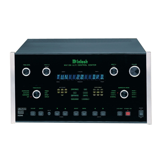
A/V Control Center
MX136
Owner's Manual
Manufactured under license from Dolby Laboratories. "Dolby", "Pro Logic" and the double-D symbol are trademarks of Dolby Laboratories.
Manufactured under license under U.S. Patent No's: 5,451,942; 5,956,674; 5,974,380; 5,978,762; 6,226,616; 6,487,535 & other U.S. and
worldwide patents issued & pending. DTS, DTS Digital Surround and Neo:6 are registered trademarks and the DTS logos and Symbol, and
DTS 96/24 are trademarks of DTS, Inc. © 1996-2007 DTS, Inc. All Rights Reserved.
McIntosh Laboratory, Inc.
2 Chambers Street
Binghamton, New York 13903-2699
Phone: 607-723-3512
FAX: 607-724-0549
Advertisement
Chapters
Table of Contents

Related Manuals for McIntosh MX136


Summary of Contents for McIntosh MX136
- Page 1 & pending. DTS, DTS Digital Surround and Neo:6 are registered trademarks and the DTS logos and Symbol, and DTS 96/24 are trademarks of DTS, Inc. © 1996-2007 DTS, Inc. All Rights Reserved. McIntosh Laboratory, Inc. 2 Chambers Street...
-
Page 2: Safety Instructions
The exclamation point within an The lightning flash with arrowhead, within an equilateral triangle, is in- equilateral triangle is intended to tended to alert the user to the presence alert the user to the presence of im- of uninsulated “dangerous voltage” portant operating and maintenance within the product’s enclosure that may (servicing) instructions in the litera-... - Page 3 Safety Instructions Outdoor Antenna Grounding If an outside antenna or cable system is connected to the product, be sure the antenna or cable system is grounded so as to provide some protection against voltage surges and built-up static charge. Article 810 of the National Electrical Code, ANSI/NFPA 70, pro- vides information with reguards to proper grounding of the mast and supporting structure, grounding of the...
-
Page 4: Table Of Contents
Customer Service How to Change the Input Setup ........33 If it is determined that your McIntosh product is in need of How to Change the Volume Setup ........38 repair, you can return it to your Dealer. You can also return How to Change the Advanced Settings ...... -
Page 5: Important Information
32. If a recording is made from the turntable and/or output (Digital or Analog) when a DTS Sound Track is listening to a record in Zone B of the MX136, both the playing. If the Digital Output is selected in the player setup... -
Page 6: Connector Information
Connector Information Keypad Terminal Connector Power Control Connector To use a WK-3 or WK-4 Keypad with the MX136, connect The MX136’s Power Control Outputs provide a 5 volt sig- the shield and four leads of a shielded 4 conductor cable to nal. -
Page 7: Introduction
Dual Zone The 12 Analog A/V Inputs can be retitled for any desired The MX136 has the built-in ability to control a separate re- signal sources. Any unused input can be “turned off” so the mote audio/video zone with program selection independent input selector will skip over it. -
Page 8: Dimensions
Dimensions Dimensions The following dimensions can assist in determining the best location for your MX136. There is additional information on the next page pertaining to installing the MX136 into cabinets. " 45.09cm Front View of the MX136 " " 7/16 22.54cm... -
Page 9: Installation
The four feet (2.54cm) in front of the mounting panel for knob clearance. may be removed from the bottom of the MX136 when it is Be sure to cut out a ventilation hole in the mounting shelf custom installed as outlined below. -
Page 10: Rear Panel Multizone, Control And Switch
Keypad or McIntosh Power Am- Source Compo- IR room sen- plifier for each Zone nents Connect the MX136 IR INPUTS VIDEO sends a DATA Ports send sig- power cord to a live for Zone A or turn On/Off sig- nals to compatible AC outlet. -
Page 11: Rear Panel Analog And Digital Audio Connections
2 supply analog digital audio signal from signal from the ana- audio record signals to the MX136 when the optional the Coaxial Output of a log inputs as selected for recorders TM1 Module is not installed or... -
Page 12: Rear Panel Video Connections
Rear Panel Video Connections OUTPUTS for VCR 1 and 2 COMPONENT INPUTS HDMI INPUTS for supply Composite Video Note: If the MX136 A/V System receive Component Video Digital Video Signals Signals for recorders Control Center has the TM1 AM/ (Y, P... -
Page 13: How To Connect Data And Power Control
How to Connect Data and Power Control How to Connect Data and Power Control 1. Connect a Data Control Cable from the MX136 AU- 6. Connect a Power Control Cable from the McIntosh DIO VIDEO (input 11) Data Port to the McIntosh AU- Powered Subwoofer Power Control Out Jack to the DIO VIDEO Player Data In Jack. -
Page 14: How To Connect Digital Audio Components
2. Connect a cable from the MX136 SAT INPUT (Input B) OPTICAL DIGITAL INPUT to the Optical Digital Output of a Satellite Receiver. 3. Connect a cable from the MX136 LV INPUT (Input C) OPTICAL DIGITAL INPUT to the Optical Digital Output of a Digital Audio Recorder. -
Page 15: How To Connect Analog Audio Components For Five Or Six Channels
McIntosh AUDIO VIDEO Player. along with the Digital Audio Signal Output from source 5. Connect a cable from the MX136 Left and Right Ana- components connected to the MX136. This will assure the log Audio INPUTs (Input 6) to the Left and Right Ana- audio from the source component is available to the REC log Audio Outputs of the Satellite Receiver. -
Page 16: How To Connect Analog Audio Components For Eight Channels
Note: In place of the Balanced Audio Cables, unbalanced cables or a DB25 cable may be used. 2. Connect a cable from the MX136 Analog Audio IN- Analog IN Analog OUT PUTS (Input 11) to the McIntosh 2 CH Audio Outputs of the McIntosh AUDIO VIDEO Player. - Page 17 How to Connect Analog Audio Components for eight channels McIntosh Powered Subwoofer Satellite Receiver McIntosh Seven Channel Power Amplifier...
-
Page 18: How To Connect Video Components
How to Connect Video Components How to Connect Video Components There are four types of Video Signals the MX136 can se- 3. Connect video cables from the MX136 DVD COMPO- lect; Composite, S-Video, Component and HDMI. The NENT INPUTS 5 to the McIntosh Component Video built-in Digital Video Processing Circuitry can Up-Convert Outputs of the McIntosh Audio Video Player. -
Page 19: How To Connect For Zone B
How to Connect for Zone B How to Connect for Zone B The MX136 is a Dual Zone A/V Control Center. For Zone 3. Connect a cable from the MX136 KEYPADS ZONE B B activation, a Power Amplifier and Loudspeakers are re- to the McIntosh Keypad. -
Page 20: Front Panel Controls And Sensor
Front Panel Controls and Sensor Allows up or down Adjusts the Listen adjustment for each Volume Level of all trim parameter eight channels Selects which of the eleven Au- Selects which of the eleven Audio/ dio/Video Sources or Tuner Video Sources or Tuner Signal is Signal is available for VCR available at the Zone A Audio Out- Outputs, Zone B Audio Outputs... -
Page 21: Front Panel Push-Button And Switch
Input Selection and into memory various Zones A or B, or resets all Volume Adjustment MX136 Settings the MX136 microproces- sors Move Up or Down through various selections and for Tuning Up or Down the AM or FM Broadcast Band... -
Page 22: Front Panel Displays
Indicates when the Indicates when the and which channels are active; L (Left Front), Input Source selected MX136 is in C (Center), R (Right Front), LFE (Low Fre- is processing a Digital Standby/On Mode quency Effects), LS (Left Surround), S (Pro... - Page 23 Notes...
-
Page 24: Remote Control Push-Buttons
LED illuminates during the Press to Power the Press MODE to switch between time a remote command is MX136 ON or OFF various Surround Modes sent to the MX136 Turns AC Power ON or OFF to Press to Power ON... -
Page 25: How To Operate By Remote Control
TM1 Tuner Module installed in the MX136 or an components and other brand source components can be con- external McIntosh Tuner connected to the MX136. trolled by the MX136 Remote Control with the addition of a McIntosh Remote Control Translator (RCT). Volume... -
Page 26: Setup Mode
4. Access the desired Setup Menu by pressing the Up some of these adjustments are interactive. or Down directional push- Note: One of the MX136 MON A Video OUTPUTS must be buttons followed by the SE- connected to the video input of a Monitor/TV for LECT/OK Push-button on viewing the On Screen Menus. -
Page 27: Default Settings
Setup 10 ......... VCR 2 ......... 33 11 ......... DVD ........... 33 Digital Inputs (Zone A): Letter Type Name Refer to Page A ..Optical ....CD 1 ........34 B ..Optical ....SAT ........34 C ..Optical ....LV ........34 ADJUSTMENTS HAVE BEEN MADE D .. -
Page 28: How To Adjust For Loudspeaker Size
YES to save those changes or NO not to Right directional push-buttons to change the current save them. The MX136 will then return to normal op- setting. eration. Refer to figure 7 on page 27. Notes: When the Front Loudspeakers are set to Small, the... - Page 29 YES to save those changes or NO not to 8. Select EXIT from the MAIN SYSTEM SETUP Menu. save them. The MX136 will then return to normal op- If you are satisfied with the changes that you may have eration.
-
Page 30: How To Adjust Loudspeaker Time Delay
If you are satisfied with the changes that you have made, select YES to save those changes or NO not to save them. The MX136 will then return to normal op- eration. Refer to figure 7 on page 27. Loudspeaker Time Delay... -
Page 31: How To Adjust Loudspeaker Levels
A properly setup Home Theater Surround Sound System will have all Loudspeaker levels adjusted to the same vol- ume level in the Listening/Viewing Area. The MX136 in- MENU: SPEAKER LEVEL cludes a built-in test signal generator and its output is... - Page 32 YES to save those changes or NO not to 10. Select EXIT from the MAIN SYSTEM SETUP Menu. save them. The MX136 will then return to normal op- If you are satisfied with the changes that you may have eration.
-
Page 33: How To Change The Input Setup
SETUP, con’t How to Change the Input Setup The MX136 has twelve Analog Audio Inputs numbered 0 through 11, six Digital Audio Inputs lettered A through F and five Component Video Inputs numbered 1 through 5. MENU: INPUT SETUP There are also four HDMI (Digital Video) Inputs numbered 1 through 4. - Page 34 ZONE A Analog Input to select “H” the second character of the title. The MX136 has two pairs of Stereo Balanced Inputs that 22. Select the two remaining characters “O” and “N” of may be assigned to any of the eleven Audio Inputs instead the title by using the directional push-buttons.
- Page 35 TV Input 7, over to the CD2 Input 3. select SOURCE INPUT from the On-Screen Menu, Notes: The MX136 allows for assigning a HDMI Video Input followed by pressing the Left or Right direc- to multiple Inputs or switched Off.
- Page 36 Component Video Input versions of Composite Video Signals to S-Video and Com- The MX136 has Electronic Input Switching for five Com- ponent Video; S-Video Input Signals may be converted to ponent Video Sources and they may be assigned to any of Component Video.
- Page 37 VCR1 Menu. If you are satisfied with the changes that you may have made, select YES to save those changes or VCR2 NO not to save them. The MX136 will then return to F-Coaxial normal Video Inputs Source Settings opera-...
-
Page 38: How To Change The Volume Setup
If you are satisfied with the changes that you may have made, select YES to save those changes or NO not to save them. The MX136 will then return to normal op- eration. Refer to figure 7 on page 27. -
Page 39: How To Change The Advanced Settings
Component Video 480p/576p 480p, 720p or 1080i Select Input Select Power On 480i, Component Video 720p Straight through The MX136 has a feature called Input Select Power On that 480p, allows for easier operation. When an Input Source Push- Component Video 1080i Straight through 720p or... - Page 40 YES to save those changes or 14. Press the SELECT/OK Push-button to return to the NO not to save them. The MX136 will then return to ADVANCED Menu. normal operation. Refer to figure 7 on page 27.
-
Page 41: How To Operate The Mx136
The McIntosh MX136 has been factory configured for de- turn Off all AC Power with the Power Switch. If the MX136 is in the Standby Mode and is connected to a fault operating settings that will allow immediate enjoyment McIntosh Audio/Video Multizone Control System... - Page 42 MX136 SETUP Mode for making changes to the Home sion function. Theater System. Reset of Microprocessors Tuning In the event that the controls of the MX136 stop function- The TUNING Up and Down Push-buttons allow for ing, there is a built-in user reset function. Press the POWER tuning up and down the FM or AM Radio Bands when the Switch to OFF and wait for two minutes.
- Page 43 Surround Mode Selector is turned to CINEMA1 or MUSIC 1 positions. H. The DIGITAL SIGNAL Display will illuminate when the MX136 is processing a Digital Encoded Signal. I. The DTS Display will illuminate when the input con- tains DTS Encoded Signals.
-
Page 44: How To Operate The Trim Mode
5 appears to the right of SUB TRIM on the Bass and Treble Front Panel Alphanumeric Display. This is an example The MX136 allows for changing the tonal response for any of increasing the Subwoofer level by 5dB. of the eleven inputs via the BASS and TREBLE Compensa- 3. - Page 45 Loudness boost will be 18dB less 10dB or 8dB. Refer to figure 43. Effects The MX136’s Trim Select Effect Mode allows for different types of audio signal processing as different Surround Modes are selected. Refer to the chart below:...
- Page 46 How to Operate the Trim Mode, con’t Center Width This mode takes some of the Center Channel Signal and adds it to the Left and Right Front Loudspeakers, thus in- creasing the width of the front sound field. The effect can be Figure 47 varied with eight different settings ranging from minimum (0) to maximum (7).
-
Page 47: How To Operate The Surround Mode
How to Operate the Surround Mode How to Operate the Surround Mode Music 2 The MX136 provides nine different Surround Modes. The The Front Panel Alphanumeric Display will indicate MU- Front Panel Alphanumeric Display and the Output Format SIC 2. Refer to figure 52. This Mode utilizes DTS NEO:6 LEDs will indicate the Surround Mode selected. - Page 48 All internal signal processing is bypassed and the eight Rear Panel EXTERNAL INPUTS are activated so the MX136 performs as an Eight Channel Preamplifier for an external source or processor. The Front Panel Alphanu- meric Display indicates EXTERNAL. Refer to figure 57.
-
Page 49: How To Make A Recording
Digital Audio Recording The separate INPUT B (Record) and INPUT A (Listen) The MX136 allows recording from any of the Digital Audio Switches allow for the making of an Analog Audio Record- Input Sources to an external Digital Recording Device. Re- ing from one program source while listening to another. -
Page 50: How To Operate Zone B
4. Press the ZONE B Push-button and then rotate the VOLUME Control to the desired volume level for Zone 5. To switch Off Zone B from the MX136 Front Panel if Zone A is already Off, press the SYS OFF Push-button. -
Page 51: Audio And General Specifications
230 Volts, 50/60Hz at 65 watts 2.5V Unbalanced Outputs (Main) 240 Volts, 50/60Hz at 65 watts 5.0V Balanced Outputs (Main) Note: Refer to the rear panel of the MX136 for the correct voltage. Maximum Voltage Output 9.5V Unbalanced Overall Dimensions 19V Balanced Width is 17-3/4 inches (45.09cm) -
Page 52: Tm1 Am/Fm Tuner Module
Introduction Cables for installing the McIntosh TM1 Cable for connecting the The MX136 A/V Control Center has provisions for adding AM/FM Tuner Mod- RAA1 to the MX136 an optional McIntosh TM1 AM/FM Tuner Module for Ra- ule into the MX136 dio Station Reception. -
Page 53: Antenna Connections
MX136 Rear Panel and RAA1 Top Panel Antenna Connections RAA1 Remote Antenna can be adjusted to a position for optimum reception of your fa- vorite AM stations Connects with supplied cable to the MX136 AM ANT (An- tenna) connector allows a McIntosh... -
Page 54: How To Connect Antenna Components
5 Pin Terminal Con- Note: If a longer length cable needs to be used between the nector Plug. Refer to the connec- MX136 and the RAA1, use a 2 conductor shielded tion information on the top cover cable. -
Page 55: How To Operate The Tuner
How to Operate the Tuner How to Tune Stations Manually The McIntosh MX136 TM1 AM/FM Tuner Module incor- porates an advanced design AM/FM Tuner with many desir- able performance features to enhance your enjoyment of ra- dio broadcasts. There are four methods of tuning to an AM/ Figure 63 FM Broadcast Station. -
Page 56: How To Assign Preset Stations
How to Assign Preset Stations How to Assign Preset Stations 6. To verify the Station Preset(s) just entered into memory, The MX136 AM/FM Tuner Module (TM1) allows for pre- press the PRESET Left and Right Push-buttons to setting radio stations into memory. To enter Presets follow cycle through and confirm your preset assignments. -
Page 57: How To Optimize Am Reception
How to Optimize AM Reception How to Optimize AM Reception The McIntosh RAA1 Remote AM Antenna is designed to former L1 for maximum signal strength. Refer to figure provide the best in AM Reception especially if the tuner or A/V unit is located in a noisy reception area. Locate the 2. -
Page 58: Am Specifications
TM1 FM and AM Specifications FM Tuner Specifications AM Tuner Specifications Useable Sensitivity Sensitivity 14dBf which is 1.4uV across 75 ohms 20uV External Antenna Input 50dB Quieting Sensitivity Signal To Noise Ratio Mono: 19dBf which is 2.4uV across 75 ohms 48dB at 30% modulation Stereo: 35dBf which is 15uV across 75 ohms 58dB at 100% modulation... -
Page 59: Packing Instructions
If a shipping car- 034301 Bottom pad ton or any of the interior part(s) are needed, please call or write Customer Service Department of McIntosh Labora- 017937 Plastic foot tory. Please see the Part List for the correct part numbers. - Page 60 McIntosh Laboratory, Inc. 2 Chambers Street Binghamton, NY 13903 The continuous improvement of its products is the policy of McIntosh Laboratory Incorporated who reserve the right to improve design without notice. Printed in the U.S.A. McIntosh Part No. 04101502...
Need help?
Do you have a question about the MX136 and is the answer not in the manual?
Questions and answers