Table of Contents
Advertisement
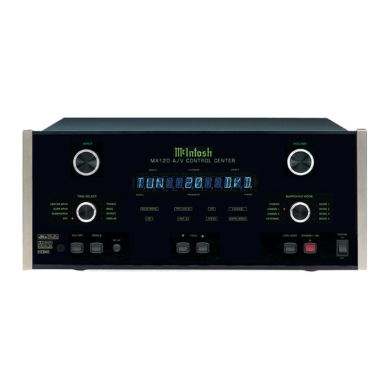
A/V Control Center
MX120
Owner's Manual
Manufactured under license from Dolby Laboratories. "Dolby", "Pro Logic" and the double-D symbol are trademarks of Dolby Laboratories.
"DTS" and "DTS Digital Surround" are registered trademarks of Digital Theater Systems, Inc.
McIntosh Laboratory, Inc.
2 Chambers Street
Binghamton, New York 13903-2699
Phone: 607-723-3512
FAX: 607-724-0549
Advertisement
Chapters
Table of Contents

Related Manuals for McIntosh MX120


Summary of Contents for McIntosh MX120
- Page 1 Manufactured under license from Dolby Laboratories. “Dolby”, “Pro Logic” and the double-D symbol are trademarks of Dolby Laboratories. “DTS” and “DTS Digital Surround” are registered trademarks of Digital Theater Systems, Inc. McIntosh Laboratory, Inc. 2 Chambers Street Binghamton, New York 13903-2699...
-
Page 2: Safety Instructions
The exclamation point within an The lightning flash with arrowhead, within an equilateral triangle, is in- equilateral triangle is intended to alert the user to the presence of im- tended to alert the user to the presence of uninsulated “dangerous voltage” portant operating and maintenance (servicing) instructions in the litera- within the product’s enclosure that may... -
Page 3: Table Of Contents
Customer Service How to Change the Input Setup ........31 If it is determined that your McIntosh product is in need of How to Change the Volume Setup ........37 repair, you can return it to your Dealer. You can also return How to Change the Advanced Settings ...... -
Page 4: Important Information
Zones A and B. 16. To view Component Video, S-Video and Composite Video 8. When a McIntosh WK-2 Keypad or a R649 Sensor is to be Input Sources through the HDMI Video Monitor A Output, it connected to the McIntosh MX120 A/V Control Center that is necessary to first go into the Setup Mode, select the Input uses a RJ-45 Connector Plug instead of the “F”... -
Page 5: Connector Information
Connector Information Keypad Terminal Connector Power Control Connector To use a WK-3 or WK-4 Keypad with the MX120, connect The MX120’s Power Control Outputs provide a 5 volt sig- the shield and four leads of a shielded 4 conductor cable to nal. -
Page 6: Introduction
Dual Zone • • Separate Listen and Record Input Selection The MX120 has the built-in ability to control a separate re- The 6 Analog Audio/Video and 2 Analog Audio only Inputs mote audio/video in Zone B with program selection indepen- can be retitled for any desired signal sources. -
Page 7: Dimensions
Dimensions Dimensions The following dimensions can assist in determining the best location for your MX120. There is additional information on the next page pertaining to installing the MX120 into cabinets. " 44.45cm Front View of the MX120 " " 19.37cm 18.10cm... -
Page 8: Installation
The four feet depth behind the front panel. Allow 1 inch (2.54cm) in front may be removed from the bottom of the MX120 when it is of the mounting panel for knob clearance. Be sure to cut out custom installed as outlined below. -
Page 9: Rear Panel Multizone, Control And Switch
Keypad or McIntosh Power Am- Source Compo- IR room sen- plifier for each Zone nents Connect the MX120 IR INPUTS VIDEO sends a DATA Ports send sig- power cord to a live for Zone A or turn On/Off sig- nals to compatible AC outlet. -
Page 10: Rear Panel Analog And Digital Audio Connections
Rear Panel Audio and Digital Audio Connections ZONE A FIXED OUTPUTS BALANCED INPUTS ZONE A BALANCED send a fixed line level, two for two channel OUTPUTS contain the channel analog signal as component sources program signals for selected by the INPUT Zone (Zone A only) Right, Center and Left A Control... -
Page 11: Rear Panel Video Connections
Rear Panel Video Connections COMPONENT INPUTS HDMI INPUTS for receive Component Video Digital Video Signals (Y, P and P ) Signals from four HDMI Video from three Component Sources Video Sources HDMI VIDEO OUT- OUTPUT MONitor A INPUTS for Composite Video Signals PUT MONitor A sends a Composite or from a VCR 1, DVD, TV, SAT, CD (2),... -
Page 12: How To Connect Multizone, Data And Power Control
How to Connect Data and Power Control How to Connect Data and Power Control 1. Connect a Data Control Cable from the MX120 DVD 5. Connect a Power Control Cable from the MX120 (Input 5) Data Port to the McIntosh Audio/Video Player POWER CONTROL ACC Jack to the McIntosh Audio Data In Jack. -
Page 13: How To Connect Digital Audio Components
1. Connect a cable from the MX120 DIGITAL COAXIAL DVD INPUT (Input E) to the McIntosh Coaxial Digital Output of the McIntosh Audio/Video Player. 2. Connect a cable from the MX120 SAT INPUT (Input C) OPTICAL DIGITAL INPUT to the Optical Digital Output of a Satellite Receiver. -
Page 14: How To Connect Analog Audio Components For Eight Channels
McIntosh AM/FM Tuner VCR1 and 2 Outputs and Zone B. 1. Connect balanced cables from the MX120 Zone A FR (Front Right), Front CENTER and FL (Front Left) BALANCED OUTPUTS to the McIntosh Seven Chan-... - Page 15 How to Connect Audio Components for eight channels Satellite Receiver Digital Audio Recorder McIntosh Powered Subwoofer Analog OUT McIntosh Seven Channel Power Amplifier...
-
Page 16: How To Connect Analog Audio Components For Five Or Six Channels
Digital Audio Signal Output from source compo- INPUTs to the McIntosh 5.1CH Audio Outputs of the nents to the MX120. This will assure the audio from the McIntosh Audio/Video Player. source component is available to the REC Outputs and 6. -
Page 17: How To Connect Video Components
How to Connect Video Components How to Connect Video Components There are four types of Video Signals the MX120 can se- 3. Connect video cables from the MX120 DVD COMPO- lect; Composite, S-Video, Component and HDMI. The NENT INPUTS 3 to the McIntosh Component Video built-in Digital Video Processing Circuitry can Up-Convert Outputs of the McIntosh Audio/Video Player. -
Page 18: How To Connect For Zone B
How to Connect for Zone B How to Connect for Zone B The MX120 is a Dual Zone A/V Control Center. For Zone 3. Connect a cable from the MX120 KEYPADS ZONE B B activation, a Power Amplifier and Loudspeakers are re- to the McIntosh Keypad. -
Page 19: Front Panel Controls And Sensor
Front Panel Controls and Sensor Selects which of the seven Au- Adjusts the Listen Volume dio/Video Sources or Tuner Level of all eight channels Signal is available at the Zone for Zone A and both chan- A and B Audio/Video Outputs nels for Zone B and for the RECord Outputs IR (Infra Red) Sensor... -
Page 20: Front Panel Push-Button And Switch
Front Panel Push-buttons and Switch Activates control of Zone B, Switches On and Off both Input Selection and Zones A or B Volume Adjustment Press to go into Activates the volume Setup Mode to compression circuit, change the settings supported by selected Dolby Digital sound tracks Switches Off the... -
Page 21: Front Panel Displays
Modes, Setup Functions Indicates when Indicates when Zone B Front the Late Night Control is active Processing has been selected Indicates the name or type of Indicates when the the Operating/Decoding Modes MX120 is in that are in use Standby/On Mode... -
Page 22: Remote Control Push-Buttons
LED illuminates during the Press to Power the Press MODE to switch between time a remote command is MX120 ON or OFF various Surround Modes sent to the MX120 Turns AC Power ON or OFF to Press to Power ON... -
Page 23: How To Operate By Remote Control
TM1 Tuner Module installed in the MX120 or an components and other brand source components can be con- external McIntosh Tuner connected to the MX120. trolled by the MX120 Remote Control with the addition of a McIntosh Remote Control Translator (RCT). Volume... -
Page 24: Setup Mode
Output connections may provide a more viewable Note: One of the MX120 MON A Video OUTPUTS must be image than the HDMI connection with some TV/ connected to the video input of a Monitor/TV for Monitors. -
Page 25: Default Settings
Setup 6 ..........VCR ........31 7 ..........TAPE ........31 Digital Inputs (Zone A): Letter Type Name Refer to Page A ....Optical ....AUX ........32 B ....Optical ....CD(2) ........32 C ....Optical ....SAT ........32 ADJUSTMENTS HAVE BEEN MADE DO YOU WANT TO SAVE THEM? D .... -
Page 26: How To Adjust For Loudspeaker Size
YES to save those changes or NO not to Right directional push-buttons to change the current save them. The MX120 will then return to normal op- setting. eration. Refer to figure 7 on page 25. Notes: When the Front Loudspeakers are set to Small, the... -
Page 27: Mc Bass Mode
YES to save those changes or NO not to 8. Select EXIT from the MAIN SYSTEM SETUP Menu. save them. The MX120 will then return to normal op- If you are satisfied with the changes that you may have eration. -
Page 28: How To Adjust Loudspeaker Time Delay
If you are satisfied with the changes that you have made, select YES to save those changes or NO not to save them. The MX120 will then return to normal op- eration. Refer to figure 7 on page 25. Loudspeaker Time Delay... -
Page 29: How To Adjust Loudspeaker Levels
A properly setup Home Theater Surround Sound System will have all Loudspeaker levels adjusted to the same vol- ume level in the Listening/Viewing Area. The MX120 in- cludes a built-in test signal generator and its output is MENU: SPEAKER LEVEL... - Page 30 YES to save those changes or NO not to 10. Select EXIT from the MAIN SYSTEM SETUP Menu. save them. The MX120 will then return to normal op- If you are satisfied with the changes that you may have eration.
-
Page 31: How To Change The Input Setup
SETUP, con’t How to Change the Input Setup The MX120 has eight Analog Audio Inputs numbered 0 through 7, six Digital Audio Inputs lettered A through F and three Component Video Inputs numbered 1 through 3. There are also four HDMI (Digital Video) Inputs numbered 1 MENU: INPUT SETUP through 4. -
Page 32: Vcr
Digital Input A, which by default has been assigned to Input Number 1 PH/AUX, over to the VCR Input (6) in- ZONE A Analog Input stead. The MX120 has one Stereo Balanced Input that may be as- 11. Using the Up or Down directional push-buttons,... -
Page 33: Surr (Surround) Mode Default: Number
22. Press the Right directional push-button to select the Video Power second character position of the title. The MX120 has a VIDEO POWER CONTROL Jack and 23. Using the Up or Down directional push-buttons its activation is controllable by selecting any one of the to select “H”... - Page 34 Input, which by default has been assigned to SAT Input 3, Input 2. over to the VCR Input 6. Notes: The MX120 allows for assigning a HDMI Video Input Note: The MX120 allows for assigning a Component Video to multiple Inputs or switched Off. If there are any...
-
Page 35: Vcr
MAIN MENU MAIN MENU Figure 23 Figure 24A The MX120 Video Converter feature allows the Up-Conver- sions of Composite Video Signals to S-Video and Compo- nent Video; S-Video Input Signals may be converted to MENU: INPUT SETUP Component Video. This will provide better picture quality... -
Page 36: Tun
Menu. If you are satisfied with the changes that you may have made, select YES to save those changes or NO not to save them. The MX120 will then return to normal operation. Refer to figure 7 on page 25. -
Page 37: How To Change The Volume Setup
If you are satisfied with the changes that you may have made, select YES to save those changes or NO not to save them. The MX120 will then return to normal op- eration. Refer to figure 7 on page 25. -
Page 38: How To Change The Advanced Settings
Component Video 480p/576p 480p, 720p or 1080i Select Input Select Power On 480i, Component Video 720p Straight through The MX120 has a feature called Input Select Power On that 480p, Component Video 1080i Straight through allows for easier operation. When an Input Source Push- 720p or... -
Page 39: Operation
18. Using the Up or Down directional push-buttons, There are different versions of the MX120 to meet the re- select YES from the On-Screen Menu, followed by quirements in each country where it is sold. The MX120 pressing the SELECT/OK Push-button. Refer to fig- can display that version information by the following steps. -
Page 40: How To Operate The Mx120
Remote Control will allow selection of either the Digital or Analog Signal Source for that MX120 is in Standby Mode and the title MX-120 will ap- assigned input. Refer to page 38 for additional pear on the Front Panel Alphanumeric Display for approxi- information. - Page 41 Reset of Microprocessors desired level in Zone B. The Zone B volume level may also In the event that the controls of the MX120 stop function- be adjusted in the Zone B Room with a Remote Control or ing, there is a built-in user reset function. Press the POWER Keypad.
- Page 42 How to Operate the MX120, con’t F. The DTS ES Display will illuminate when the input contains DTS ES Encoded Signals. G. The NEO:6 Display will illuminate when the Sur- round Mode Selector is turned to CINEMA2 or MU- SIC 2 positions.
-
Page 43: How To Operate The Trim Mode
INPUT A Listen Control or SURROUND MODE Control is changed. Figure 37 Bass and Treble The MX120 allows for changing the tonal response for any 2. Press the Front Panel TRIM LEVEL Up or Down of the eight inputs via the BASS and TREBLE Compensa- Push-button until the number 5 appears to the right of tion TRIM Adjustments. - Page 44 Left and Right Front Loudspeakers, thus in- Effects creasing the width of the front sound field. The effect can be The MX120’s Trim Select Effect Mode allows for different varied with eight different settings ranging from minimum types of audio signal processing as different Surround (0) to maximum (7).
- Page 45 How to Operate the Trim Mode, con’t Figure 46 6. Press the Front Panel TRIM LEVEL Up or Down Push-button to select one of the many different sound effects available. Display Brightness The brightness of the Front Panel Alphanumeric Display may be adjusted using the Display Trim Feature.
-
Page 46: How To Operate The Surround Mode
How to Operate the Surround Mode How to Operate the Surround Mode the Trim Effect Setting for “Center Width”, refer to page 47 The MX120 provides nine different Surround Modes. The to alter the settings. Front Panel Alphanumeric Display and the Output Format LEDs will indicate the Surround Mode selected. - Page 47 2. Using the Remote Control, press the HOME Push-but- Rear Panel EXTERNAL INPUTS are activated so the ton followed by pressing immediately the Left MX120 performs as an Eight Channel Preamplifier for an Right directional push-buttons to select the desired external source or processor.
-
Page 48: How To Make A Recording
How To Make A Recording How To Make A Recording Analog Audio Recording Note: The MX120 record OUTPUTS are not affected by the VOLUME, SURROUND or TRIM controls. To listen The INPUT Selector Switch together with the Zone B Push-... -
Page 49: How To Operate Zone B
4. Press the ZONE B Push-button and then rotate the VOLUME Control to the desired volume level for Zone 5. To switch Off Zone B from the MX120 Front Panel if Zone A is already Off, press the SYS OFF Push-button. -
Page 50: Specifications
230 Volts, 50/60Hz at 65 watts 2.5V Unbalanced Outputs (Main) 240 Volts, 50/60Hz at 65 watts 5.0V Balanced Outputs (Main) Note: Refer to the rear panel of the MX120 for the correct voltage. Maximum Voltage Output 9.5V Unbalanced Overall Dimensions 19V Balanced Width is 17-1/2 inches (44.45cm) -
Page 51: Packing Instructions
If a shipping car- ton or any of the interior part(s) are needed, please call or 017937 Plastic foot write Customer Service Department of McIntosh Labora- 400159 #10-32 x 3/4” screw tory. Please see the Part List for the correct part numbers. - Page 52 McIntosh Laboratory, Inc. 2 Chambers Street Binghamton, NY 13903 The continuous improvement of its products is the policy of McIntosh Laboratory Incorporated who reserve the right to improve design without notice. Printed in the U.S.A. McIntosh Part No. 04101601...
Need help?
Do you have a question about the MX120 and is the answer not in the manual?
Questions and answers