
Related Manuals for McIntosh MHA150


Summary of Contents for McIntosh MHA150
-
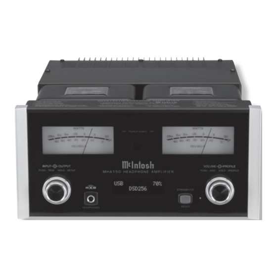
Page 1: Headphone Amplifier
McIntosh Laboratory, Inc. 2 Chambers Street Binghamton, New York 13903-2699 Phone: 607-723-3512 www.mcintoshlabs.com MHA150 Headphone Amplifier Owner’s Manual... -
Page 2: Safety Instructions
he lightning flash with arrowhead, within an equilateral triangle, The exclamation point within an equilateral triangle is intended to is intended to alert the user to the presence of uninsulated “dan- alert the user to the presence of important operating and mainte- gerous voltage”... -
Page 3: Table Of Contents
Thank You Customer Service Your decision to own this McIntosh MHA150 Head- If it is determined that your McIntosh product is in Setup Mode: con’t phone Amplifier ranks you at the very top among need of repair, you can return it to your Dealer. You Input Renaming ............ -
Page 4: General Information
MHA150. with the other McIntosh Component and look in Input Connectors on the MHA150. Refer to the dia- 2. Apply AC Power to the MHA150 and other McIn- the “Setup Section - Remote Control Codes” of gram for connection:... -
Page 5: Introduction
Power Supply ensure stable The patented McIntosh Power Guard circuit prevents The MHA150 consists of a 50 watts per channel stereo noise free operation even though the power line varies. amplifier clipping and protects your valuable Head- Power Amplifier with less than 0.005% distortion. -
Page 6: Dimensions
Dimensions Dimensions The following dimensions can assist in determining the best location for your MHA150. There is addition- al information on the next page pertaining to install- ing the MHA150 into cabinets. Front View of the MHA150 " 29.2cm "... -
Page 7: Installation
Installation Installation The MHA150 Headphone Ampifier is designed to be placed upright on a table or shelf, standing on its feet. The required ventilation requirements are shown. Always provide adequate ventilation for your MHA150. Cool operation ensures the longest possible 6"... -
Page 8: Rear Panel Connections
Digital OPTICAL, COXIAL and MCT Digital Outputs sending digital audio signals Main Fuse holder, refer to information on the back panel of your MHA150 to determine the correct fuse size and rating PWR CNTRL (Power Control) IN BALANCED INPUTS... - Page 9 Notes...
-
Page 10: Connecting Components And Optional Loudspeakers
(7.62 meters) (15.24 meters) (30.48 meters) Impedance terclockwise until an opening page 12. If the MHA150 will be used with an exter- or less or less or less appears. Refer to figures A and nal Power Amplifier, please refer to page 13. - Page 11 Terminal to the Loudspeaker Terminal Connections being careful to observe the correct polarities. Refer to “General Information” Note 7 on page 4 for additional information. 5. Connect the MHA150 power cord to an active AC Connect to Computer outlet. AC Outlet Spade Lug or Wire Connections: 6.
-
Page 12: System Thru Connections
System Thru Connections System Thru Connections The MHA150 can also be part of an existing Audio or Audio/Video Sound System. The MHA150 allows connection of Headphones for private listening. It can also drive Loudspeakers in a second room. The Preamplifier MHA150 becomes active when the Main Preamplifier or Audio/Video Controller is On. -
Page 13: External Power Amplifier Connections
External Power Amplifier Connections External Power Amplifier Connections The MHA150 has the ability to drive an External Power Amplifier. In the example below, the MHA150 automatically switches the External Power Amplifier On/Off via Power Control function. 1. Connect Audio Cables from the MHA150 PRE- AMPlifier OUTPUT Jacks to the External Power Amplifier IN (Left and Right) Jacks. -
Page 14: Remote Control Push-Buttons
Mutes and unmutes the audio Powers the MHA150 ON or OFF Selects the PREVIOUS Station Selects the NEXT Station Preset Preset on contemporary McIntosh on contemporary McIntosh Tuners Tuners Note: Push-buttons whose function is not identified above are for use with other McIntosh Products. -
Page 15: How To Use The Remote Control
The supplied Remote Control performs the various Operating Functions for the MHA150 Headphone When using an optional contemporary McIntosh Tuner with the MHA150, select the next Station Preset Amplifier. Note: Refer to the “How to Operate” Section of this by pressing the : Push-button. Select the previous manual for additional information. -
Page 16: Front Panel Displays, Controls, Push-Button And Jack
OUTPUT Control allows the Indicates the Dynamic Crossfield STANDBY/ON Push-button with selection of either Headphones circuitry is active when illuminated indicator switches the MHA150 (various impedances) or Loud- ON or OFF (Standby) and resets speakers. When in Setup Mode the microprocessors... -
Page 17: How To Operate The Setup Mode
UNBAL vided to customize the operating settings using the V_._ _ NAME: UNBAL Front Panel Display. Refer to the MHA150 Front Panel MHA150 S/N: AET_ _ _ _ _ Figure 3 Illustration on the previous page while performing an INPUT NAME... -
Page 18: Firmware Version
ANCED, OPTICAL, COAX and AES/EBU as indi- NAME: MNBAL the Firmware in the MHA150 can be identified at any cated on the Front Panel Display) can be customized time by utilizing the Setup Mode. with a different name up to eight characters long (My Figure 6 1. -
Page 19: Speaker Mode
Speaker Mode Subwoofer Mode to 80Hz. It is recommended the Professionals The MHA150 is designed to work with an external The MHA150 allows for the connection of Loudspeak- at your McIntosh Dealer, who are skilled in all ers with different performance capabilities. One of the Powered Subwoofer. -
Page 20: Remote Control
McIntosh component located in the the Setup Menu item “VOLUME GUARD, En- In Progress! same room as the MHA150. Refer to “General Infor- abled” appears on the Front Panel Display. Refer to mation, note 6” on page 4 for additional information. -
Page 21: How To Operate The Mha150
Trim Setting. To verify The Red LED beside the STANDBY/ON Push-button Control. Refer to figures 50 and 52. lights to indicate the MHA150 is in Standby mode. a TRIM Setting without changing it, press the To switch ON the MHA150, press the STANDBY/ON... -
Page 22: Balance
Source Components can have slightly different volume indicate the Input Selection and Volume Level. INPUT Control to select the OPTICAL Input and levels resulting in the need to readjust the MHA150 note if the relative volume is louder or quieter Volume Control when switching between different BALANCE than the volume level of the UNBAL. -
Page 23: Meter Lights
Power Amplifiers will also switch On/Off when trol to enter the TRIM Mode. Then rotate the ____ connected to the MHA150 via a power control INPUT Control until “DISPLAY INFO, Sample cable. Refer to “Power Control Connections” Rate” appears on the Front Panel Display. Refer to Figure 63 on page 4. -
Page 24: Headphone Jack, Headphone Hxd Tm
® ) listening. Refer to the chart below. phone Listening. HXD restores the directionality default Profile Setting is for the McIntosh MHP1000 ® component of the spatial sound stage normally heard OUTPUT CONTROL SELECTION with Loudspeaker listening. To activate the HXD ®... - Page 25 How to Operate the MHA150, con’t 2. If desired, select the HXD Mode by momentarily Refer to figure 84. SAVE PROFILE pressing the VOLUME Control. The HXD Icon NAME PROFILE Profile2 located above the Headphone Jack will illuminate Profile2 Green. Refer to figure 71.
-
Page 26: Power Output Meters And Power Guard
Guard Indicators will momentarily illuminate during Figure 89 21. Rotate the VOLUME Control to select “DELETE peaks in the audio signals. In the event the MHA150 15. To exit the Profile Rename Mode momentarily over heats, due to improper ventilation, high ambient ALL, Saved Profiles”. -
Page 27: Optical And Coaxial Digital Inputs
McIntosh USB Audio Software Driver needs to be Audio Input has the latest firmware version, if not control on the MHA150 should be set to 70%. The installed on the PC Computer. The driver needs to be update the firmware first. - Page 28 Control Panel Settings Figure 113 Upon completion of in- To activate the McIntosh-HD USB Audio Control stalling the driver, figure Panel, click on the “McIntosh Icon” (located in the 114 will appear. Windows notification Figure 114 area on the right side of...
-
Page 29: Of Microprocessors
Figures 121 and 122 indicate a Sampling Rate of 128 STANDBY/ON Push-button. or 256 times the Sampling Rate of a CD Disc for the Note: This can be performed with the MHA150 On or in the Standby Mode. incoming DSD Digital Audio Signal. -
Page 30: Specifications
8V unbalanced Total Harmonic Distortion Standby: Less than 0.25 watt 16V balanced Note: Refer to the rear panel of the MHA150 for the cor- 0.005% maximum with both channels operating from rect voltage. Preamplifier Output Impedance 250 milliwatts to rated power, 20Hz to 20,000Hz... -
Page 31: Packing Instructions
If a shipping carton or any of the interior part(s) are needed, please call or write Customer Service Depart- ment of McIntosh Laboratory. Refer to page 3. Please see the Part List for the correct part numbers. LEFT FOAM... - Page 32 McIntosh Laboratory, Inc. 2 Chambers Street Binghamton, NY 13903 www.mcintoshlabs.com The continuous improvement of its products is the policy of McIntosh Laboratory Incorporated who reserve the right to improve design without notice. Printed in the U.S.A. McIntosh Part No. 04165200...
Need help?
Do you have a question about the MHA150 and is the answer not in the manual?
Questions and answers