Table of Contents
Advertisement
OWNER’S
MANUAL
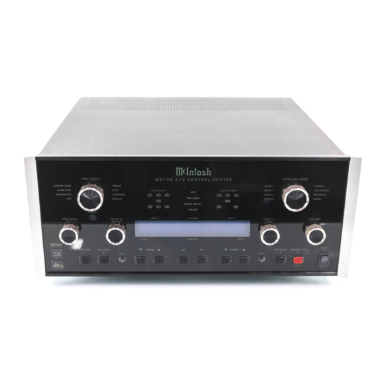
MX132 A/V Control Center
Manufactured under license from Dolby Laboratories, “Dolby”, “Pro Logic” and the double-D symbol
MX132
are registered trademark of Dolby Laboratories. “DTS”, “digital surround”, and “coherent acoustics”
are registered trademark of DTS Technology, LLC. and manufactured under license from DTS Tech-
nology LLC. Lucasfilm, THX, the THX logo, Re-Equalization, Re-EQ, Timbre Matching,
Decorrelation, Bass Management, and Loudspeaker Position Time Synchronization are registered
trademarks of Lucasfilm, Ltd and manufactured under license from Lucasfilm Ltd.
McIntosh Laboratory, Inc. 2 Chambers Street Binghamton, New York 13903-2699 Phone: 607-723-3512 FAX: 607-724-0549
Advertisement
Table of Contents

Related Manuals for McIntosh MX132


Summary of Contents for McIntosh MX132
- Page 1 LLC. Lucasfilm, THX, the THX logo, Re-Equalization, Re-EQ, Timbre Matching, Decorrelation, Bass Management, and Loudspeaker Position Time Synchronization are registered trademarks of Lucasfilm, Ltd and manufactured under license from Lucasfilm Ltd. McIntosh Laboratory, Inc. 2 Chambers Street Binghamton, New York 13903-2699 Phone: 607-723-3512 FAX: 607-724-0549...
- Page 2 Thank You, Please Take A Moment, Customer Service and Table of Contents Thank You Table of Contents Please Take A Moment Connections Serial Number: Purchase Date: Dealer Name: Technical Assistance Front Panel Features Remote Control Setup Mode Customer Service Operation ©...
-
Page 3: General Notes
Table of Contents con’t, Notes and Connector Information Table of Contents con’t Additional Information General Notes Data and Power Control Cable Part No. 170-202 Control Center to Multi Channel Power Amplifier Cable Part No. 170-631 Control Center to CR12 Cable Part No. 170-430 CR12 Keypad Terminal Plug Part No. -
Page 4: Safety Instructions
Safety Instructions IMPORTANT SAFETY INSTRUCTIONS! Attention: pour pevenir les chocs elecriques pas utiliser cette fiche polarisee avec un prolongateur, une prise de courant ou un autre sortie de courant, PLEASE READ THEM BEFORE sauf si les lames peuvent etre inserees afond ans en OPERATING THIS EQUIPMENT. - Page 5 Safety Instructions Repair of Equipment: Outdoor Antenna: Care of Equipment:...
- Page 6 Introduction and Performance Features · Introduction LED Channel Status Indicators · Pure Stereo Outputs Performance Features · 24 Bit DSP Processing and Conversion · Adjustable Channel Level · Adjustable Time Delay · Digital Audio Input Switching · Precision Tracking Volume Control ·...
- Page 7 Performance Features con’t · Special FM RF Amplifier · Multifunction Fluorescent Display · FM Stereo Auto Blend Circuitry · Signal Processing ® · Preset Stations · External AM RF Amplifier · Permanent Memory · Late Night Dynamic Audio Compression · Dual Zone ·...
- Page 8 Installation Installation 17-1/2" 444mm 17-1/16" 433.4mm 1/4" Outline of Front Panel Edge of Cutout Front View of the MX132 7/32" 5.3mm End Caps custom installed 7-1/16" Panel Height 6-9/16" 179.8mm (Front View) 7.00" 166.7mm 177.8mm 3/16" 5.1mm Support Shelf Bottom of Cutout and Top...
-
Page 9: Antenna Connections
MX132 Rear Panel Multizone, Control and Antenna Connections MX132 Rear Panel Multizone, Control and RAA1 Remote Antenna can be adjusted to a position for optimum reception of your fa- Antenna Connections vorite AM stations Connects with TO MULTIZONE supplied cable to... - Page 10 MX132 Rear Panel Audio and Digital Connections MX132 Rear Panel Audio and Digital Connections INPUTS CD2, TV and DVD INPUTS for audio signals from a receive a digital audio signal DVD, LV, VCR, TV, SAT, CD, from the Coaxial Output of...
- Page 11 MX132 Rear Panel Video Connections MX132 Rear Panel Video Connections OUTPUT MONitor A send a INPUTS for Composite Video Signals Composite or S Video Signal to a from a DVD, LV, VCR, TV, SAT, CD, monitor/TV located in Zone A...
- Page 12 How to Connect Multizone, Control and Antenna Components How to Connect Multizone, Control and Antenna Components FM Antenna McIntosh Laser Video Disc Player McIntosh CR12 Multizone Controller McIntosh WK-3 Keypad IR Sensor To AC outlet McIntosh HC-1 McIntosh RFD2 AC-3...
- Page 13 How to Connect Audio and Digital Components How to Connect Audio and Digital Components McIntosh MLD7020 Video Disc Player McIntosh MCD7010 CD Player Satellite Receiver DVD Player Digital Signal Processor McIntosh RFD2 AC-3 RF Demodulator McIntosh MC7205 Power Amplifier...
-
Page 14: How To Connect Video Components
How to Connect Video Components How to Connect Video Components McIntosh MLD7020 Video Disc Player Monitor Satellite Receiver DVD Player... - Page 15 How to Connect the MX132 for Zone B How to Connect the MX132 for Zone B DVD Player Monitor McIntosh MC122 Power Amplifier McIntosh WK-4 Keypad 1 2 3 4 5 6 7 8 9 1 2 3 4 5 6 7 8 9...
- Page 16 Front Panel Controls, Pushbuttons, Switch and Sensor Front Panel Controls, Pushbuttons, Switch and Sensor Selects the parameter Places the MX132 Selects the desired Turns all for making audio and circuits in the tuner audio operating mode AC Power front panel display ad-...
-
Page 17: Front Panel Displays
Indicates when Indicates when Setup Indicates whenever Record Lock is Mode is active the MX132 Power active switch is turned on Indicates input status, volume, Indicates when volume tuner functions, trim adjust- compression circuit is ments, surround modes and... - Page 18 VCR/ Selects the Surround TAPE recorder operating mode functions Mutes the audio Press to turn the entire MX132 System OFF, including INPUT B/ Record (Zone B) and any McIntosh Multizone Controllers Adjusts the volume level up or down...
- Page 19 How to Operate the Remote Control How to Operate the Remote Control Mute Home Sys Off Audio Power CD/Tape Mode Tuner Pushbuttons Level ACC ON - OFF Volume Trim Alternate MX132 Pushbutton Functions Numbered Pushbuttons...
- Page 20 SETUP How to Operate the Setup Mode Main System Setup Menu Figure 3 Figure 1 Figure 4 Figure 2 Figure 5...
-
Page 21: Default Settings
SETUP Default Settings Default Settings MENU: MAIN SYSTEM SETUP ( SELECT WITH NUMBER ) 1. SPEAKER SIZE 2. SPEAKER TIME DELAY Speaker Size: 3. SPEAKER LEVEL 4. ANALOG INPUTS 5. DIGITAL INPUTS 6. VIDEO POWER CONTROL 7. VIDEO CONVERTER 8. ZONE B VOLUME PRESET 9. - Page 22 SETUP Default Settings, con’t Digital Inputs (Zones A): Surround Modes (Zones A): Video Input Power Control: Video Input Converter: Audio Functions:...
-
Page 23: How To Adjust For Loudspeaker Size
SETUP How to Adjust for Loudspeaker Size MENU: SPEAKER SIZE ( SELECT WITH NUMBER ) 1. FRONT: SMALL {THX} 2. CENTER: SMALL {THX} 3. SURROUND: SMALL {THX} 4. SUBWOOFER: YES 5. DTS FULL RANGE MODE: OFF ( PRESS E TO EXIT ) Figure 8 t l u i t t... - Page 24 SETUP How to Adjust Speaker Time Delay How to Adjust Speaker Time Delay Figure 5 Figure 3 MENU: MAIN SYSTEM SETUP MENU: SPEAKER TIME DELAY ( SELECT WITH NUMBER ) ( SELECT WITH NUMBER AND 1. SPEAKER SIZE ADJUST WITH LEVEL UP/DOWN ) 2.
- Page 25 SETUP How to Adjust Speaker Time Delay, con’t Figure 10 t l u i t t i t t t f e t f 0 r e t t f 0 t f 0 t f 0 t f e t f 0 r e f t f 0...
- Page 26 SETUP How to Adjust Speaker Levels How to Adjust Speaker Levels MENU: SPEAKER LEVEL (SELECT WITH NUMBER AND ADJUST WITH LEVEL UP/DOWN) 1. AUTOMATIC (OFF) 2. MANUAL (OFF) LEFT FRONT CENTER RIGHT FRONT RIGHT SURROUND 0 LEFT SURROUND SUBWOOFER 3. BASS LIMITER OR EXIT Figure 11 Automatic Loudspeaker Level Switching Figure 12...
- Page 27 SETUP How to Adjust Speaker Levels, con’t Manual Speaker Level Switching MENU: BASS LIMITER (SELECT WITH NUMBER) 1. LIMITER (OFF) (PRESS E TO EXIT) Figure 13...
- Page 28 SETUP How to Adjust Speaker Levels, con’t and the Bass Limiter MENU: BASS LIMITER SETUP (SELECT WITH NUMBER AND ADJUST WITH LEVEL UP/DOWN) 1. LIMITER (ON) 2. CALIBRATE LIMITER LEVEL 0 t l u i t t i t t (PRESS E TO EXIT) t f e r e t...
- Page 29 SETUP How to Reassign the Analog Inputs How to Reassign the Analog Inputs (Audio and Video) MENU: ANALOG INPUTS ( SELECT WITH LEVEL UP/DOWN PRESS INPUT SOURCE BUTTON AND NUMBER ) 0. TUN1 4. TP1 8. LV1 1. AUX1 5. TP2 9.
- Page 30 SETUP How to Reassign the Digital Inputs How to Reassign the Digital Inputs MENU: DIGITAL INPUTS ( SELECT WITH LEVEL UP/DOWN PRESS INPUT SOURCE BUTTON AND NUMBER ) A. CD1 D.CD2 B. SAT1 E. TV1 C. LV1 F. DVD1 ( PRESS E TO EXIT ) Figure 16 Figure 17 Turning Off a Digital Input...
- Page 31 SETUP How to Assign the Video Power Control How to Assign Video the Power Control MENU: VIDEO POWER CONTROL ( SELECT WITH LEVEL UP/DOWN CHANGE WITH MODE BUTTON) 0. ON 4. ON 8. ON 1. ON 5. ON 9. ON 2.
- Page 32 SETUP How to Assign the Video Converter How to Assign the Video Converter MENU: VIDEO CONVERTER ( SELECT WITH LEVEL UP/DOWN CHANGE WITH MODE BUTTON) 0. OFF 4. OFF 8. OFF 1. OFF 5. OFF 9. OFF 2. OFF 6. OFF 10.
- Page 33 SETUP How to Adjust Zone B Volume Preset and Optimize AM Reception How to Adjust Zone B Volume Preset How to Optimize AM Reception NON - METALLIC Figure 21 MENU: ZONE B VOLUME PRESET NON-METALLIC ( ADJUST WITH LEVEL UP/DOWN ) ( PRESS E TO EXIT ) Figure 20...
- Page 34 OPERATION How to Operate the MX132 Volume Control and Volume Level Display Power On and Off 0 to 99 Input A and B Selector Figure 22 System Off Late Night Reset of Microprocessors Front Panel Status LED’s Figure 23...
- Page 35 OPERATION How to Operate the MX132, con’t Figure 24 How To Make A Tape Recording...
- Page 36 OPERATION How to Operate the FM Tuner How to Operate the FM Tuner How to Assign FM Presets How to tune FM Stations Manually Figure 25 Figure 27 Figure 28 Figure 26...
- Page 37 OPERATION How to Operate the FM Tuner, con’t How to Tune FM Stations with Tuner Presets How To Clear an FM Preset Number Figure 29 l l a e t t y t i...
- Page 38 OPERATION How to Operate the AM Tuner How to Operate the AM Tuner How to Assign AM Presets How to tune AM stations Manually Figure 30 Figure 32 Figure 31 Figure 33...
- Page 39 OPERATION How to Operate the AM Tuner, con’t How to Tune AM Stations with AM Tuner Presets How to Clear an AM Preset Number Figure 34 l l a e t t y t i...
- Page 40 OPERATION How to Operate the Trim Mode How to Operate the Trim Mode Loudspeaker Level Figure 35 Figure 38 Figure 36 Figure 39 Figure 37...
- Page 41 OPERATION How to Operate the Trim Mode, con’t Loudness Compensation Bass and Treble Figure 42 Display Brightness Figure 40 Figure 43 Figure 41...
- Page 42 OPERATION How to Operate the Surround Mode How to Operate the Surround Mode Figure 44 Music 1, 2 and 3 Surround Modes Figure 48 Music 3 Stereo Mode Figure 49 Music 2 Figure 45 Figure 46 Figure 47 Figure 50...
- Page 43 OPERATION How to Operate the Surround Mode, con’t Music 1 Figure 54 External Figure 51 Figure 55 Mono Figure 52 Cinema Figure 53 Figure 56 THX Cinema Figure 57 Figure 58...
- Page 44 OPERATION How to Operate Remote Zones How to Operate Zone B Figure 59 Figure 60 Figure 61 Rec Lock...
- Page 45 OPERATION How to Operate Remote Zones, con’t How to Operate Additional Zones Figure 62 Zone B Tone Controls Figure 64 Figure 63...
- Page 46 Performance Charts Bass Control Adjustment Range (Decibel) 50 60 70 400 500 600 Hz (Hertz) Loudness Control Adjustment Range (Decibel) 50 60 70 80 100 400 500 600 Hz (Hertz)
- Page 47 Performance Charts, con’t Treble Control Adjustment Range (Decibel) Hz (Hertz)
- Page 48 Performance Charts, con’t Analog Output Frequency Response (Decibel) Hz (Hertz) Digital Output Frequency Response (Decibel) Hz (Hertz)
-
Page 49: Specifications
Specifications FM Tuner Specifications AM Tuner Specifications Useable Sensitivity Sensitivity 50dB Quieting Sensitivity Signal To Noise Ratio Signal To Noise Ratio Harmonic Distortion Frequency Response Frequency Response Adjacent Channel Selectivity Harmonic Distortion Image Rejection IF Rejection Audio Specifications Intermodulation Distortion Frequency Response Capture Ratio Alternate Channel Selectivity... - Page 50 General Specifications con’t Audio Specifications, con’t Voltage Gain Frequency Response Tone Controls General Specifications Power Requirements Rated Output Dimensions Input Impedance Output Impedance Weight Maximum Output Voltage Total Harmonic Distortion Sensitivity Signal To Noise Ratio - All Outputs Maximum Input Signal...
- Page 51 Packing Instructions Packing Instructions...
Need help?
Do you have a question about the MX132 and is the answer not in the manual?
Questions and answers