Table of Contents
Advertisement
Quick Links
Advertisement
Chapters
Table of Contents

Related Manuals for JEOL JEM-2100F


Summary of Contents for JEOL JEM-2100F
- Page 1 INSTRUCTIONS JEM-2100F FIELD EMISSION ELECTRON MICROSCOPE For the proper use of the instrument, be sure to read this instruction manual. Even after you read it, please keep the manual on hand so that you can consult it whenever necessary. IEM210F-1 (17200)
- Page 2 JEM-2100F FIELD EMISSION ELECTRON MICROSCOPE EM210F-1...
- Page 3 · In no event will JEOL Ltd. be liable for direct, indirect, incidental or conse- quential damages resulting from the use of software described in this manual.
- Page 4 NOTATIONAL CONVENTIONS AND GLOSSARY ■ General notations An imminent hazardous situation which, if not avoided, will result DANGER: in death or serious injury. A potentially hazardous situation which, if not avoided, could WARNING: result in death or serious injury. A potentially hazardous situation which, if not avoided, could CAUTION: result in minor or moderate injury.
-
Page 5: Table Of Contents
CONTENTS SAFETY PRECAUTIONS 1. GENERAL 2. SPECIFICATIONS PERFORMANCE ..................2-1 ELECTRON OPTICAL SYSTEM............2-2 2.2.1 Illuminating System ................2-2 2.2.2 Image Forming System ..............2-2 SPECIMEN STAGE................2-2 CAMERA CHAMBER ................2-3 EVACUATION SYSTEM ..............2-3 2.5.1 For Microscope Column..............2-3 2.5.2 For Electron Gun Chamber .............2-3 2.5.3 Vacuum Valves ................2-3 CONTROL SYSTEM ................2-3 INSTALLATION REQUIREMENTS............2-4... - Page 6 CONTENTS 4.2.4 Control Panel R2................4-9 4.2.5 Control Panel SC ................4-10 4.2.6 Power Supply Console..............4-11 MONITOR DISPLAY ................4-14 4.3.1 Page 1 ....................4-14 4.3.2 Page 2 ....................4-15 4.3.3 Page 3 ....................4-16 4.3.4 Page 4 ....................4-16 4.3.5 Page 5 ....................4-17 PC SCREENS..................4-18 4.4.1 Application Start-up ..............4-18 4.4.2 TEM Controller Screen ..............4-19...
- Page 7 CONTENTS 5.5.3 High Dispersion Electron Diffraction ...........5-45 USE OF THE ANTICONTAMINATION DEVICE ......5-47 5.6.1 Filling the Refrigerant Tank............5-47 5.6.2 Raising the Trap Temperature to Room Temperature ....5-48 SPECIAL OPERATION...............5-51 5.7.1 Alignment Data Saving ..............5-51 5.7.2 Free Lens Control (FLC)...............5-52 APPENDIX ..................5-53 5.8.1 Microscope Console and Column ..........5-53 5.8.2...
-
Page 8: Safety Precautions
For the proper use of the instrument, be sure to read the following safety precautions prior to starting operation or maintenance. They contain important information related to safety. Contact your JEOL service office whenever you are unclear about any operation or maintenance. - Page 9 Do not make any modification such as removing protective parts, ex- changing component parts, or unlocking or defeating safety devices. · The instrument and related attachments should be installed by JEOL en- gineers. Please contact your nearest JEOL subsidiary if installation is required.
-
Page 10: General
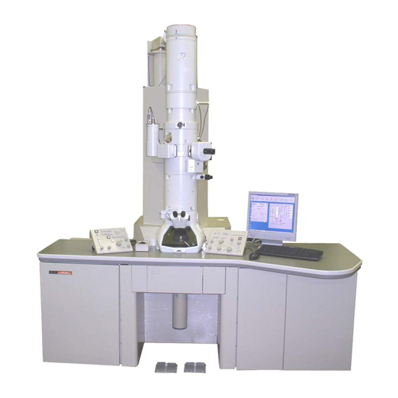
GENERAL EM210F-1... - Page 11 1 GENERAL The JEM-2100F is a high resolution analytical electron microscope in the van of the new era accomplished by further improving the JEM-2101F field emission electron microscope that had a ultra high image quality and resolution in 200 kV class electron microscopes.
-
Page 12: Specifications
SPECIFICATIONS PERFORMANCE....................2-1 ELECTRON OPTICAL SYSTEM..............2-2 2.2.1 Illuminating System ................... 2-2 2.2.2 Image Forming System................2-2 SPECIMEN STAGE ................... 2-2 CAMERA CHAMBER ..................2-3 EVACUATION SYSTEM .................. 2-3 2.5.1 For Microscope Column................2-3 2.5.2 For Electron Gun Chamber................. 2-3 2.5.3 Vacuum Valves ................... -
Page 13: Performance
2 SPECIFICATIONS This section covers the principal specifications relative to setting up and operating the microscope. PERFORMANCE Accelerating voltage: 160 and 200 kV. 80, 100 and 120 kV are optionally available. High dispersion diffraction camera length: 4 to 80 m (14 steps). High resolution diffraction camera length: 333 mm (high resolution diffraction stage: optional). -
Page 14: Electron Optical System
2 SPECIFICATIONS ELECTRON OPTICAL SYSTEM 2.2.1 Illuminating System · Electron gun Emitter: ZrO/W (100) Electron gun lens: Electrostatic lens. Axis alignment: Electromagnetic 2-stage interlocking system. Airlock: Automatic. · Condenser lens Type: Three-stage (1st, 2nd and mini). 10, 40, 100, 250 mm in diameter (click stop type). Aperture: Stigmator: Electromagnetic type complete with centering device. -
Page 15: Camera Chamber
2 SPECIFICATIONS When the EM-20458 polepiece is used: ± 60 ° (single tilt) · Specimen shift: Motor driven (X, Y and Z directions), A trackball and buttons are used. CAMERA CHAMBER · Film Standard size: A, E, J or S size Loading capacity: Up to 50. -
Page 16: Installation Requirements
2 SPECIFICATIONS INSTALLATION REQUIREMENTS 2.7.1 Power, Water and Nitrogen Gas · Power source: Single-phase, 200/220/240 V, 10.0 kVA (7 kVA in normal condition) · Grounding terminal: One, 100 ohms or less. · Cooling water: Flow rate: 7.5 L/min. Pressure: 0.2 to 0.3 MPa (Gauge pressure). Temperature: 15 to 20℃. -
Page 17: Dimensions And Weight (Mm And Kg)
2 SPECIFICATIONS DIMENSIONS AND WEIGHT (MM AND KG) Height Depth Width Mass Main console 2,530 1,740 2,250 1,200 Power supply 1,750 HT tank 1,640 1,210 Rotary Pump* Dry pump* The number of pumps depends on the evacuation system. · In the case of the EM-23075 with EM-23080 evacuation system Two oil rotary pumps ·... -
Page 18: Composition And Construction
COMPOSITION AND CONSTRUCTION COMPOSITION....................3-1 ACCESSORIES....................3-1 CONSTRUCTION OF COLUMN ..............3-2 3.3.1 Column Exterior ..................3-2 3.3.2 Column Interior ..................3-3 3.3.3 Location of Coils and Lenses ..............3-4 LOCATION OF CONTROL PANELS............... 3-5 RAY DIAGRAMS ....................3-6 3.5.1 Illumination System ................... -
Page 19: Composition
3 COMPOSITION AND CONSTRUCTION COMPOSITION The figure shown below is the layout diagram when the EM-23075 and EM-23080 are used in the JEM-2100F as the evacuation system. Drain Power distributor Water supply Air compressor HT tank Power supply Oil rotar y pumps... -
Page 20: Construction Of Column
3 COMPOSITION AND CONSTRUCTION CONSTRUCTION OF COLUMN 3.3.1 Column Exterior Optional attachments are included in this photograph and the shape may not be identical with yours in detail. Condenser aperture assembly High contrast objective aperture assembly CM lens shift screws (4 pcs) Goniometer Specimen holder Refrigerant tank... -
Page 21: Column Interior
3 COMPOSITION AND CONSTRUCTION 3.3.2 Column Interior Electron gun Accelerating tube Electron gun 1st beam deflector coil Electron gun 2nd beam deflector coil Gas inlet Electron gun chamber isolation valve 1st condenser lens coil Condenser lens stigmator coil 2nndd condenser lens coil Condenser lens 1st beam Goniometer deflector coil... -
Page 22: Location Of Coils And Lenses
3 COMPOSITION AND CONSTRUCTION 3.3.3 Location of Coils and Lenses Emitter Electrostatic lens Electron gun 1st beam deflector coil Electron gun 2nd beam deflector coil 1st condenser lens coil 2nd condenser lens coil Condenser lens stigmator coil Condenser lens 1st beam deflector coil Condenser lens 2nd beam deflector coil Condenser minilens (CM lens) coil Objective lens coil... -
Page 23: Location Of Control Panels
3 COMPOSITION AND CONSTRUCTION LOCATION OF CONTROL PANELS Control panel R2 is accessible by pulling out panel R2 housing and control panel L2 is accessible when cover L2 is opened. The PC is accessible when cover PC is opened. Control panel SC Monitor Control panel L1 Control panel R1... -
Page 24: Ray Diagrams
3 COMPOSITION AND CONSTRUCTION RAY DIAGRAMS 3.5.1 Illumination System Fig 3.6 Ray diagram (Illumination system) EM210F-1... -
Page 25: Image Forming System
3 COMPOSITION AND CONSTRUCTION 3.5.2 Image Forming System Fig 3.7 Ray diagram (image forming system) EM210F-1... -
Page 26: Description Of Controls
DESCRIPTION OF CONTROLS (See Fig. 3.2) COLUMN .................. 4-1 4.1.1 Condenser Aperture Assembly..............4-1 4.1.2 Condenser Mini Lens Shift Screws ............4-1 4.1.3 Specimen Holder ..................4-1 4.1.4 Goniometer....................4-1 CONTROL PANELS..................4-3 4.2.1 Control Panel L1..................4-3 4.2.2 Control Panel R1 ..................4-6 4.2.3 Control Panel L2.................. - Page 27 4.4.4c Right main screen................4-21 4.4.5 Menu Bar ....................4-22 4.4.5a File.....................4-22 4.4.5b Dialogue ....................4-22 4.4.5c Monitor....................4-22 4.4.5d Property .....................4-22 4.4.5e Option....................4-23 4.4.5f Maintenance ..................4-23 4.4.5g Display....................4-23 4.4.5h JEOLS ....................4-23 4.4.5i Help ....................4-23 4.4.6 Screens from the Menu Bar ..............4-24 4.4.6a Photo History screen................4-24 4.4.6b High Voltage Control screen .............4-25 4.4.6c...
-
Page 28: Column
4 DESCRIPTION OF CONTROLS COLUMN (See Fig. 3.2) 4.1.1 Condenser Aperture Assembly l Condenser aperture assembly ( Fig. 4.1) Knob 1: The apertures are selected corresponding to the knob 1 position. Knob 1 position Aperture size Open Knobs 2 and 3: Knobs 2 and 3 are used to move the apertures in X and Y directions. - Page 29 4 DESCRIPTION OF CONTROLS ① ④ ② ③ Fig. 4.2 Goniometer ① Green lamp Indicates, when lit, that specimen holder insertion and removing is ready. ② Yellow lamp Indicates, when lit, that the goniometer is being roughly evacuated. ③ PUMP/AIR switch Setting this switch to PUMP evacuates the goniometer (the yellow lamp lights up during evacuation) and the goniometer vacuum is broken when this switch is set to AIR.
-
Page 30: Control Panels
4 DESCRIPTION OF CONTROLS CONTROL PANELS 4.2.1 Control Panel L1 ② ① ④ ③ ⑤ ⑧ ⑨ ⑩ ⑪ ⑦ ⑥ Fig. 4.3 Control panel L1 ① BEAM VALVE switch Pressing this switch opens valve V1 (isolation valve between the microscope column and electron gun chamber). - Page 31 4 DESCRIPTION OF CONTROLS · Aperture number select switches When one of these switches is depressed, the corresponding aperture size of the selected aperture assembly is selected. OPEN: The aperture is opened. Aperture number 1 is selected. Aperture number 2 is selected. Aperture number 3 is selected.
- Page 32 4 DESCRIPTION OF CONTROLS PLA switch: Used to vary the projector lens deflector coil current when shifting the diffraction spot or specimen image. COND STIG switch: Used to adjust the condenser lens stigmator coil current when performing the condenser lens astigmatism correc- tion.
-
Page 33: Control Panel R1
4 DESCRIPTION OF CONTROLS 4.2.2 Control Panel R1 ① ⑩ ⑪ ⑦ ② ⑨ ⑧ ③ ④ ⑥ ⑤ Fig. 4.4 Control panel R1 ① WOBBLER switches IMAGE WOB X: Used for focusing. The 1st and 2nd beam deflector coil currents vary periodically when this switch is turned on. - Page 34 4 DESCRIPTION OF CONTROLS SA DIFF switch: Used for selecting the selected area diffraction mode. ③ SHIFT Y knob Used for shifting the electron beam in the Y direction by varying the condenser lens beam deflector coil current. The electron gun 1st beam deflector coil current is varied when the Align-Gun is selected on the Alignment Panel for Maintenance screen.
-
Page 35: Control Panel L2
4 DESCRIPTION OF CONTROLS The timing of the film advancement and the photo- graphing can set on the Film Camera Property screen. Lamp: Indicates, when lit, that the shutter ⑨ STD FOCUS switch Depressing this switch sets the objective lens current to the original reference value. ⑩... -
Page 36: Control Panel R2
4 DESCRIPTION OF CONTROLS 4.2.4 Control Panel R2 Fig. 4.6 Control panel R2 Variable resistors (round holes): Used for maintenance. Dip switches (square holes): Used for turning on and off lens current and deflector coil current power supplies. EM210F-1... -
Page 37: Control Panel Sc
4 DESCRIPTION OF CONTROLS 4.2.5 Control Panel SC ④ ① ③ ② Fig. 4.7 Control panel SC ① ▲ switches Used for to the specimen in the X and Y directions. ② Trackball Used to shift the specimen. The shift specimen image shift direction is roughly same as the direction in which the ball is turned. -
Page 38: Power Supply Console
4 DESCRIPTION OF CONTROLS 4.2.6 Power Supply Console ① ② ③ ④ ⑤ Fig. 4.8 Power Supply console ① Control panel P1 SIP POWER SUPPLY (20 L) ② Control panel P2 SIP POWER SUPPLY (60 L) ③ Control panel P3 (optional attachment) SIP POWER SUPPLY (150 L) ④... -
Page 39: Control Panel P1
4 DESCRIPTION OF CONTROLS 4.2.6a Control panel P1 This is a power supply for the 20 L ion pump (used for the electron gun chamber evacuation). ① ② ③ ④ ⑤ Fig. 4.9 Control panel P1, P2 ① Meter Displays the value selected with the METER RANGE knob (P1-⑤). ②... -
Page 40: Control Panel P3
4 DESCRIPTION OF CONTROLS 4.2.6c Control panel P3 This is a power supply for the 150 L ion pump (an optional attachment used for the microscope column evacuation). ① ② ④ ③ Fig. 4.10 Control panel P3 ① Meter Displays the value selected with the METER RANGE knob (P3-④). ②... -
Page 41: Monitor Display
4 DESCRIPTION OF CONTROLS MONITOR DISPLAY 4.3.1 Page 1 ② ③ ① ④ ⑤ ⑥ ⑧ ⑦ ⑨ ⑫ ⑩ ⑭ ⑪ ⑮ ⑬ ⑯ ⑰ Fig. 4.11 Page 1 ① Used to adjust the monitor brightness. ② Displays the image forming mode selected with the FUNCTION (R1-③). ③... -
Page 42: Page 2
4 DESCRIPTION OF CONTROLS 4.3.2 Page 2 ① ③ ② ④ Fig. 4.12 Page 2 ① Same as ① on Page 1. ② Same as ②, ③, ④, ⑤ and ⑥ on Page 1. ③ Displays the power values of the lenses. ④... -
Page 43: Page 3
4 DESCRIPTION OF CONTROLS 4.3.3 Page 3 ① ② ③ ④ Fig. 4.13 Page 3 ① Same as ① on Page 1. ② Same as ②, ③, ④ and ⑤ on Page 1. ③ Displays the power values of the coils. ④... -
Page 44: Page 5
4 DESCRIPTION OF CONTROLS 4.3.5 Page 5 ② ③ ① ④ Fig. 4.15 Page 5 ① Same as ① on Page 1. ② Same as ②, ③, ④ and ⑤ on Page 1. ③ Self Diagnosis Displays the system abnormality. Indicates, when lit, that the pressure in the vacuum reservoir is higher than the specified value. -
Page 45: Pc Screens
4 DESCRIPTION OF CONTROLS PC SCREENS 4.4.1 Application Start-up 4.4.1a TEM Server Double-clicking the TEM Server icon on the PC monitor start up the TEM Server. The icon is also displayed on the task tray. Fig. 4.16 TEM Server icon TEM Server icon Fig. -
Page 46: Tem Controller Screen
4 DESCRIPTION OF CONTROLS 4.4.2 TEM Controller Screen ① ③ ② ④ Fig. 4.19 TEM Controller Screen ① Switches Pressing one of these switches selects a function used routinely. Sect. 4.4.3 for the detail. ② Main screen This screen is divided in five sections. Sect. -
Page 47: Main Screen
4 DESCRIPTION OF CONTROLS 4.4.4 Main Screen Right main screen Left main screen Center main screen Fig. 4.20 Main screen 4.4.4a Left main screen ① ③ ⑤ ⑥ ② ④ ⑦ Fig. 4.21 Left main screen ① HT or Emission ·... -
Page 48: Center Main Screen
4 DESCRIPTION OF CONTROLS 4.4.4b Center main screen ③ ① ② ④ Fig. 4.22 Center main screen ① MAG Shows the present magnification. ② Defocus Displays the deference between the reference focus value and the present focus value in mm. ③... -
Page 49: Menu Bar
4 DESCRIPTION OF CONTROLS 4.4.5 Menu Bar Fig. 4.24 Menu bar 4.4.5a File · Photo history Opens the Photo History screen ( Sect. 4.4.6a). The screen shows the photo- graphing history. · Exit Terminates the TEM Controller. 4.4.5b Dialogue · High Voltage Control Opens the High Voltage Control screen ( Sect. -
Page 50: Maintenance
Used to display the TEM Control screen at the display front. · ShrtCut Displays the short cut screen ( Sect. 4.4.3) on the monitor. 4.4.5h JEOLS Used for the instrument maintenance carried out by the JEOL service engineer. 4.4.5i Help · Instruction Displays the instrument Instruction Manual. · Version Displays the instrument software version information. -
Page 51: Screens From The Menu Bar
4 DESCRIPTION OF CONTROLS 4.4.6 Screens from the Menu Bar This describes the display contents, function of the buttons briefly. Chapter 5 for the details. 4.4.6a Photo History screen Photograph information shown on the TEM Controller screen is saved on this screen when photographing. -
Page 52: High Voltage Control Screen
4 DESCRIPTION OF CONTROLS ⑤ Illumination condition when the photographing is performed ( Fig. 4.21). Illumination: The illumination mode when the photographing is performed (Left main screen ①) Spot: The spot size value when the photographing is performed (Left main screen ③) Alpha: The a -value when the photographing is performed (Left main screen ④) -
Page 53: Operation Screen
4 DESCRIPTION OF CONTROLS ② Auto HT and Emission Used for automatic high voltage generation and electron beam generation. ③ Quick Emission Selector (QES) Not used in this instrument. ④ Auto Wobbler Used for electron gun alignment. ⑤ HT Used for accelerating voltage setting. ◄ and ► buttons vary the voltage and the amount of the voltage change per step can be set in the Step box. - Page 54 4 DESCRIPTION OF CONTROLS ④ Alpha Used to vary the electron beam convergent angle. ⑤ Bright/Dark Used to select the bright field image (Bright) or dark field image (dark). ⑥ Function Used to select the image forming system. The magnification, camera length or spectrum in the selected mode can be varied with the MAG/CAM L knob (R1-⑤).
- Page 55 OFF is selected. The value is set to the small value when “1” is selected and to the large value when “3” is selected. STD Focus: Changes the focus value to that is designated by the JEOL service engineer. EM210F-1 4-28...
- Page 56 4 DESCRIPTION OF CONTROLS l Stage screen This is used when a specimen holder is inserted in the microscope column. ② ① ③ Fig. 4.30 Stage screen ① SHIFT The ► and ◄ buttons shift the specimen in the X directions and the ▲ and ▼ buttons shift the specimen in the Y directions.
-
Page 57: Specimen Position Screen
4 DESCRIPTION OF CONTROLS 4.4.6d Specimen Position screen ② ① ③ Fig. 4.31 Specimen position screen ① Coordinates Shows the present specimen position and the positions stored in the memories. ② Position Memory Window: Shows the specimen position when the Memory button is depressed. -
Page 58: Film Camera Property Screen
4 DESCRIPTION OF CONTROLS 4.4.6e Film Camera Property screen ① ③ ② ④ ⑤ ⑥ ⑦ ⑧ Fig. 4.32 Film Camera Property screen ① Curr. Dens Shows the electron beam density (pA/cm ) on the fluorescent screen. ② Exp Time Shows the exposure time for the manual exposure mode. -
Page 59: Status Monitor Screen
4 DESCRIPTION OF CONTROLS ⑥ HISTORY Opens the Photo History screen ( Sect. 4.4.6a). ⑦ Text Opens the screen on which the text can be written. ⑧ No. Opens the screen on which the film number can be changed 4.4.6f Status Monitor screen l Standard screen The information shown in this screen is the same as that shown in the main screen on the... - Page 60 4 DESCRIPTION OF CONTROLS l Alignment voltage screen The data of all the beam deflectors is shown on this screen. Fig. 4.35 Alignment Voltage screen l High Voltage screen This screen shows the accelerating voltage, electron beam current and anode voltage. Depressing the FEG Control Panel opens the High Voltage Control screen ( Sect.
-
Page 61: Valve Status Screen
4 DESCRIPTION OF CONTROLS l Alarm screen Fig. 4.37 Alarm screen When any abnormality is detected, the background of the related item on this screen turns to red. AIR: The compressed air pressure is insufficient. The pressure in the compressed air reservoir is too low. PIG: The Pirani gauge is damaged. -
Page 62: Eos Property Screens
4 DESCRIPTION OF CONTROLS ① System diagram This shows the state of the valves and Pirani gauges. The valve lamp lights up when the valve opens and the lamp goes out when the valve closes. ② Gauge status Column: The state of the microscope column vacuum and reading of the Pirani gauge 1 are shown. -
Page 63: Specimen Property Screen
4 DESCRIPTION OF CONTROLS ④ Image/Shift/Tilt Used to set the wobbler for the image shift coil, electron beam shift coil and tilt coils. “Frequency” is used to vary the wobbler frequency and “Amplitude” is used to vary the wobbler frequency. l Etc screen ①... -
Page 64: Mds Screen
4 DESCRIPTION OF CONTROLS ① Holder Used to select the specimen holder to be used. ② Apply The system confirms the selected specimen holder when this button is clicked. ③ Holder Exchange Clicking this button moves the specimen to the neutral position. This is used when removing the specimen holder from the goniometer. -
Page 65: Free Lens Control Screen
4 DESCRIPTION OF CONTROLS ④ Delay Time Used to set the delay time. 4.4.6k Free Lens Control screen ① ② ④ ⑤ ③ ⑥ ⑦ Fig. 4.43 Free Lens Control screen ① Off/On Turns on and off the free lens control function of the individual lens. ②... -
Page 66: Mag Select Screen
4 DESCRIPTION OF CONTROLS 4.4.6l Mag select screen Fig. 4.44 Mag Select screen Removing the check mark in the check boxes disables from using the corresponding magnification and camera length. All the magnifications and camera lengths having no check mark are ignored when the MAG/CAM knob is turned. 4.4.6m Lens/Def Memory screen ①... -
Page 67: Alignment Panel For Maintenance Screen
4 DESCRIPTION OF CONTROLS 4.4.6n Alignment Panel for Maintenance screen ① ② ③ ⑤ ④ ⑦ ⑥ Fig. 4.46 Alignment Panel for Maintenance screen ① DEF Select Gun: Assigns the “Gun Shift” function to the SHIFT knobs (L1-③, R1-③) and “Gun Tilt” function to the DEF/STIG knobs (L1-⑩, R1-⑤). -
Page 68: Bake Out/Acd Screens
4 DESCRIPTION OF CONTROLS ④ Freq/Amp… Opens the EOS Property screen ( Sect. 4.4.6h) for setting the frequency and amplitude of the wobblers. ⑤ Wobbler Clicking this button pulsates the high voltage. Used for the voltage center adjustment. Gun: Clicking this button pulsates the coil current in the electron gun beam deflector. - Page 69 4 DESCRIPTION OF CONTROLS l Bake Out screen ① ③ ② ④ ⑤ ⑥ ⑦ ⑧ Fig. 4.48 BAKE Out screen ① Bake Out Opens the Bake Out screen. ② Start Starts the bake-out. ③ Stop Stops the bake-out. ④ Bar Shows the bake-out process.
-
Page 70: Aperture Screen
4 DESCRIPTION OF CONTROLS 4.4.6p Aperture screen This is for aperture control when the motor drive aperture assembly is used. ① ② ③ Fig. 4.49 Aperture screen ① Adjust Mode Turns on and off the Adjust Mode. ② Backlash Correction Sets the backlash in the X and Y directions of the aperture shift. -
Page 71: Stage Limit Screen
4 DESCRIPTION OF CONTROLS 4.4.6q Stage Limit screen ① ② ③ Fig. 4.50 Stage Limit screen ① S/W limited Alarms that the specimen movement (X, Y, Z, Tilt-X and/or Rotator) reached the limit (the corresponding lamp lights up). The movement is detected using a poten- tiometer in this case. -
Page 72: Emergency Screen
4 DESCRIPTION OF CONTROLS 4.4.7 Emergency Screen This screen appears when any abnormality is detected in the microscope. The item concerning the abnormality is underlined and the left side lamp lights up. This screen will disappear when the cause of the abnormality is removed. The abnormality sign left displayed unless the abnormality is removed. -
Page 73: Operation
OPERATION EMERGENCIES ....................5-1 5.1.1 Power Suspension..................5-1 5.1.2 Cooling Water Suspension................5-1 5.1.3 Faulty Operation..................5-1 METHOD A ....................... 5-2 5.2.1 Startup Procedure ..................5-2 5.2.2 Shut Down Procedure................. 5-2 5.2.3 Film Loading ....................5-2 5.2.3a Loading films into the dispensing magazine........5-2 5.2.3b Inserting/removing the magazines into/ from the camera chamber .. - Page 74 METHOD B......................5-25 5.3.1 Conditions for High Resolution Microscopy..........5-25 5.3.2 Illumination System Alignment..............5-28 5.3.3 Condenser Lens Astigmatism Correction..........5-29 5.3.4 Beam Deflector Adjustment ..............5-29 5.3.4a Tilt adjustment...................5-29 5.3.4b Shift adjustment.................5-30 5.3.5 Voltage/current Center Adjustment ............5-30 5.3.5a Current center adjustment..............5-31 5.3.5b Voltage center adjustment..............5-31 5.3.6 Objective Lens Astigmatism Correction ..........5-32 5.3.6a...
-
Page 75: Emergencies
5 OPERATION This chapter describes the operation procedures up to and including image recording. Method A covers the startup, image recording, and shutdown procedure, and method B the procedure for routine observation. The symbols L1, R1 and SC appearing in parentheses after the names of panel controls designate the respective control panels. -
Page 76: Method A
5 OPERATION METHOD A It is advisable to become familiar with method A before attempting method B. Procedures detailed in this section are skeletonized in the section on method B. 5.2.1 Startup Procedure Open the cooling water faucet. Turn on the main power switch on the distribution board and open the nitrogen gas source valve. -
Page 77: Inserting/Removing The Magazines Into/ From The Camera Chamber
5 OPERATION Emulsion Film Cassette Dispensing Dispensing magazine magazine Bottom plate Receiving magazine Fig. 5.1 Loading films into the dispensing magazine Fig. 5.2 Magazines 5.2.3b Inserting/removing the magazines into/ from the camera chamber Make sure valve V1is closed. Open the nitrogen gas source valve and turn the camera chamber door handle clockwise until it stops. - Page 78 5 OPERATION Dispensing magazine Receiving magazine Magazine stand Magazine stand handle Fig. 5.3 Magazine stand If there is an empty dispensing magazine in the magazine stand, remove it by lifting it out. Then place the dispensing magazine loaded with unexposed films squarely in the magazine stand.
-
Page 79: Loading The Specimen Holder With A Specimen
5 OPERATION Fig. 5.4 Writing the UNUSED number 5.2.3c Loading the Specimen Holder with a Specimen Insert the cartridge removing tool into the cartridge fixing nipper at the specimen holder end, open the nipper by raising the tool and remove the cartridge from the holder. -
Page 80: Inserting The Specimen Holder In The Microscope Column
5 OPERATION Insert the cartridge removing tool into the cartridge fixing nipper at the specimen holder end, open the nipper by raising the tool and remove the cartridge from the holder. Insert the cartridge into the cartridge fixing nipper at the specimen holder end, align the guide hole on the cartridge with the guide pin on the nipper and nip the cartridge by lowering the tool. -
Page 81: Removing The Specimen Holder From The Goniometer
5 OPERATION Click “Apply” on the screen. Fig. 5.7 Specimen Property screen CAUTION • Be careful not to pinch your fingers between the specimen holder and goniometer. • Always hold the specimen holder while the holder is being inserted into the goniometer. If you do not do so, the specimen holder may hit the goniometer causing damage to the goniometer due to the force of vacuum. -
Page 82: Electron Beam Generation
5 OPERATION Open the nitrogen gas source valve. Remove the holder from the goniometer. Pull the specimen holder until it stops. Turn it fully counterclockwise. Pull it until it stops Turn it fully counterclockwise. Set the PUMP/AIR switch on the goniomter and wait 30 seconds. Remove the holder from the goniomter. -
Page 83: Ht Conditioning
5 OPERATION Start up HT conditioning 100 kV generation Electron beam generation Increasing to 200 kV Microscopy Is the generation to be stopped? Close valve V1 Stop the beam generation Close valve V1 Set the HV to 100 kV Set the HV to 160 kV Turn off the HV Resuming microscopy Resuming microscopy... - Page 84 5 OPERATION Fig. 5.10 High Voltage Control screen Increase the voltage to 200 kV as follows. Increase the voltage to 140 kV at the speed of 1 kV per minute. Increase the voltage to 180 kV at the speed of 1 kV per 15 minutes. Leave it for 10 minutes.
- Page 85 5 OPERATION Accelerating voltage 200 kV 180 kV 140 kV 100 kV Time elapsed 40 s 10 m 40 s 20 m 40 s 30 m 40 s 45 m 40 s Conditioning knob Electron gun chamber OPERAT OPERAT e (COND) Fig.
-
Page 86: Accelerating Voltage Generation
90 minutes. Make sure that the “Emission Current” on the screen is the specified value or less. If the “Emission Current” is not the specified value, open the FEG and QES setting screen and consult the JEOL service center. EM210F-1 5-12... -
Page 87: Beam Generation Stopping In The Automatic Mode
Beam generation in the manual mode will be possible if the beam is stopped manually and the special mode for maintenance is used. This operation should be performed under the directions from a JEOL service office. -
Page 88: Beam Generation Stopping It Manual Mode
Fig. 5.12 Emitter temperature setting 5.2.4g Beam generation stopping it manual mode This operation should be performed under the directions from a JEOL service office. Close isolation valve V1. Minimize the value on the “Monitor” of “A1…” using the triangle buttons. -
Page 89: Aperture Insertion
5 OPERATION 5.2.5 Aperture Insertion 5.2.5a Condenser aperture This aperture restricts the illumination area on the specimen and illumination angle. The larger the aperture size, the larger the illumination angle. The image brightness becomes brighter when a bigger aperture is used. Obtain the MAG mode. -
Page 90: Objective Aperture
5 OPERATION 5.2.5b Objective aperture Insert a specimen into the beam path ( a specimen holder’s Instruction manual) and, depress the SA DIFF switch (R1-②). Converge the electron beam with the BRIGHTNESS knob (L1-⑥) and keep the electron beam converged. Obtain a caustic spot (zero magnification spot) with the DIFF FOCUS knob (R1-⑥) as shown below. -
Page 91: Photographing
5 OPERATION 5.2.5c Field limiting aperture The field limiting aperture is used to limit an area on the specimen for observing a diffraction diagram. Set the FUNCTION (R1-②) to SA MAG, MAG1 or MAG2. Select a magnification to be used using the MAG/CAM L knob (R1-⑤). Manipulate aperture assembly knob 1 to insert an aperture to be used. - Page 92 5 OPERATION Fig. 5.18 Film Camera Property screen Set the exposure time by manipulating the EXP TIME knob (R1-⑧) or using the triangle buttons on the “Exp Time” line on the “Film Camera Property” screen ( Sect. 4.4.6e). Depress the PHOTO switch (R1-⑧) to bring the film to the photographing position.
-
Page 93: Automatic Exposure
5 OPERATION 5.2.6c Automatic exposure Depress the AUTO switch (R1-⑧) (built-in lamp lights up) or give a check mark to the “Auto Exposure” box of the “Film Camera Property” screen ( Sect. 4.4.6e) to obtain the automatic exposure mode. Manipulate the image brightness (L1- ⑥ ) to obtain an optimum image brightness. -
Page 94: Image Observation
5 OPERATION 5.2.7 Image Observation This describes the operation for the conventional image observation assuming that the automatic exposure mode is used ( Sect. 5.2.6). Prepare the specimen for observation ( Sects. 5.2.3d, 5.2.3e). Generate an electron beam ( Sect. 5.2.4). Obtain the beam on the florescent screen. - Page 95 5 OPERATION Binoculars Body tubes Focusing knob Eyepieces Screen lever Fig. 5.22 Manipulate the focusing knob of the binoculars to focus the binoculars on the small screen. First, focus the whole binoculars with the focusing knobs, and adjust, if necessary, the interocular distance by changing the distance between the body- tubes, and focus the eyepieces by turning the knurled ring ( Fig.
-
Page 96: Film Processing
5 OPERATION 5.2.8 Film Processing Unload the receiving magazine from the camera chamber ( Sect. 5.2.3). Adjourn to a darkroom and remove the lid from the receiving magazine and the cassettes from the magazine under a safelight (red lamp). Carefully remove the film from the cassette. Film Cassette Fig. - Page 97 5 OPERATION Store the dried film in a negative bag (polyethylene, cellophane, etc.) and keep the bag in a dry place away from direct sunlight. Consequences of faulty film processing, etc. are listed in Table 1 (assuming that the exposure is in order). Hanger Drying cabinet Film...
- Page 98 5 OPERATION Table 5.1 Consequence of faulty film processing Appearance Possible cause ● No picture Film inserted into cassette upside-down. ● Complete blackening Magazine lid inadvertently opened while being carried. ● Fogging Faulty safelight. Film processing date has expired. ● High density Developer temperature too high.
-
Page 99: Method B
5 OPERATION METHOD B 5.3.1 Conditions for High Resolution Microscopy ■ The electron bean divergence angle must be small High resolution micrographs will be difficult to obtain due to low coherence when the electron beam divergence angle is large. Therefore, use a small condenser aperture (100 or 40 micron meters in diameter), manipulate the BRIGHTNESS knob to obtain 2 to 4 seconds of exposure time and set the beam divergent angle as follows using the The a -SELECTOR No. - Page 100 5 OPERATION ■ The objective aperture must be properly inserted. Fig. a shows a hole image when the objective aperture is properly inserted into the electron beam path. In this figure, the background structure is readily discernible, and the edge of the hole can be clearly observed all the way round. On the other hand, Fig. b shows a hole image when the aperture is improperly inserted.
- Page 101 5 OPERATION a: Hole image when b: Hole image when astigmatism does not exist astigmatism exists Fig. 5.27 Effect of objective lens astigmatism ■ The specimen must be tightly secured. If the specimen is not tightly secured, it will result as time passes in a gradual shift of the specimen (image).
-
Page 102: Illumination System Alignment
5 OPERATION ■ Others If the specimen is contaminated, it is difficult to focus the image correctly, and photographs obtained will be obscure even though the image is properly focused. In order to prevent contamination by the electron beam, avoid irradiating the specimen for a long time. -
Page 103: Condenser Lens Astigmatism Correction
5 OPERATION 5.3.3 Condenser Lens Astigmatism Correction When astigmatism exists in the condenser lens, the shape of the electron beam when converged maximally on the screen is elliptical and image brightness is insufficient. Making the converged electron beam circle performs astigmatism correction. Select “Maintenance”... -
Page 104: Voltage/Current Center Adjustment
5 OPERATION 5.3.4b Shift adjustment This is to adjust the ratio of the current in the condenser lens beam deflector upper coil and lower coil so that the electron beam deviation when tilting the beam is minimum. Select “Maintenance” on the “TEN Controller” main menu to display the “Alignment Panel for Maintenance”... -
Page 105: Current Center Adjustment
5 OPERATION 5.3.5a Current center adjustment Select “Maintenance” on the “TEN Controller” main menu to display the “Alignment Panel for Maintenance” screen. Obtain an image in the MAG mode. Focus the image using OBJ FOCUS (R1-⑥). Diverge the beam to the extent of the entire fluorescent screen. Bring a conspicuous image to the screen center. -
Page 106: Objective Lens Astigmatism Correction
5 OPERATION 5.3.6 Objective Lens Astigmatism Correction Fig. 5.31 5.3.6a At Middle Magnifications A perforated, thin plastic film reinforced with carbon is recommended as a test specimen for astigmatism correction. Select “Maintenance” on the “TEN Controller” main menu to display the “Alignment Panel for Maintenance”... -
Page 107: At High Magnifications
5 OPERATION B: when astigmatism exists a: when astigmatism does not exist Fig. 5.32 Astigmatism in the objective lens 5.3.6b At High Magnifications An amorphous specimen (the specimen supporting film itself or specimen itself) is used for astigmatism correction at high magnifications. Select “Maintenance”... -
Page 108: Image Focusing
5 OPERATION 5.3.7 Image Focusing Image focusing at low magnifications is easy when the image wobbler is used. Focusing at high magnifications however, is not easy with the image wobbler. Image focusing with Fresnel fringe is recommended at high magnifications. At very high magnifications, micro particles on the specimen are used for image focusing. - Page 109 5 OPERATION Table 5.2 IMAGE X or Y switch Under-focus In-focus Over-focus EM210F-1 5-35...
-
Page 110: Using Fresnel Fringe
5 OPERATION 5.3.7b Using Fresnel Fringe Manipulate the OBJ COARSE (R1-⑥) to obtain the sharpest possible image (coarse focusing). While observing a portion of the image having the greatest contrast (a film hole or dust particle is ideal for practice purpose) through the binoculars, turn the OBJ FOCUS-FINE knob (R1-⑥) slightly counterclockwise and clockwise and obtain an in-focus. -
Page 111: Focusing With Fine Structure
5 OPERATION 5.3.8 Focusing with Fine Structure Utilizing the background structure in conjunction with the Fresnel fringe (over-focus or under-focus) is very effective for increasing the focusing accuracy when focusing images at magnifications of 100,000 times or more. that is to say, focus the image as precisely as possible with the fringe at under-focus, and then finely focus the image (in-focus) so as to minimize background structure contrast. -
Page 112: Special Observation
5 OPERATION SPECIAL OBSERVATION 5.4.1 Bright Field Image When the incident electron beam passes through the specimen, it splits chiefly into unscattered electron beam and scattered (diffracted) electron beam; the former forms a bright field image. Obtain a selected area image ( Sect. -
Page 113: Low Magnification Image
5 OPERATION The center spot in the diffraction diagram is called as “direct spot” and other spots are called as “Diffraction spots”. Depress the MAG1 switch (R1-②) to obtain the MAG mode. Adjust the image brightness using the BRIGHTNESS knob (L1-⑥). A dark field image (Fig. -
Page 114: Astigmatism Correction
5 OPERATION 5.4.3c Astigmatism Correction Depress the OBJ STIG switch (L1-⑤) or turn on “DEF Select-OL STIG” on the “Alignment Panel for Maintenance” screen. Depress the IMAGE WOBBLER X switch (R1-①) to turn on the switch. Focus the image using the OBJ FOCUS knob (R1-⑥). Turn off the IMAGE WOBBLER X switch (R1-①). -
Page 115: Minimum Dose Exposure (Mds)
5 OPERATION 5.4.4 Minimum Dose Exposure (MDS) This operation reduces considerably the electron beam irradiation on the specimen. The electron beam illuminates the specimen while photographing is performed only. Three modes are provided (SEARCH FOCUS and PHOTO SET). Carry out the initial setting. Select “Option”... - Page 116 5 OPERATION Set the PHOTO SET mode. Select “Photo Set” on the MDS screen. Set the image brightness, magnification and photographing condition. Generally, the electron beam is converged and the field of view is narrowed as much as possible and the manual exposure mode is used for photographing in this mode.
-
Page 117: Electron Diffraction
5 OPERATION ELECTRON DIFFRACTION 5.5.1 Selected Area Diffraction An electron beam passing through the small area limited by a field limiting aperture forms a selected area diffraction pattern. Obtain a conventional image on the screen. Depress the SA MAG switch (R1-②) to obtain the SA MAG mode. Manipulate the MAG/CAM L knob (R1-⑤) to select a magnification to be used. -
Page 118: Microbeam Electron Diffraction
5 OPERATION 5.5.2 Microbeam Electron Diffraction A finely converged electron beam, illuminating only a very small area on the specimen, forms a diffraction pattern in this method (also called “microarea”, “nanoarea”, or “converged” electron diffraction). Obtain a conventional image on the screen. Depress the MAG1 (R1-③), and select the desired magnification in the TEM mode. -
Page 119: High Dispersion Electron Diffraction
5 OPERATION 5.5.3 High Dispersion Electron Diffraction The maximum lattice spacing that can be analyzed by the selected area diffraction method is on the order of 10 nanometers. This can be extended, however, to 1,000 nanometers by means of the high dispersion electron diffraction method. However, since the specimen in this method is easily charged with electrons, coat the specimen on both sides with carbon if specimen conductivity is very low. - Page 120 5 OPERATION a: Micrograph of optical replica b: Corresponding high dispersion diffraction pattern Fig. 5.41 High dispersion diffraction EM210F-1 5-46...
-
Page 121: Use Of The Anticontamination Device
If the yellow lamp on the connector box lights up when the check button is depressed, stop the instrument operation and contact the JEOL service repre- sentative. Protect the viewing window glass with the covers provided. -
Page 122: Raising The Trap Temperature To Room Temperature
5 OPERATION Remove the funnel from the refrigerant tank and place the cap on the opening. Do not admit air into the column unless the trap temperature has risen to room temperature ( Sect. 5.6.2). Refrigerant inlet port HTR socket Connector box Yellow lamp Check button... - Page 123 5 OPERATION Fig. 5.43 Bake Out/ACD Heat screen If the refrigerant drainer cable is disconnected while the ACD HEAT button lamp is lit, the lamp will remain lit. In this case, connect the cable to the tank again, and wait for the lamp to go out. In order to terminate trap heating before the trap reaches room temperature, depress the “Off”...
- Page 124 5 OPERATION Plug Protective cylinder Heater Fig. 5.44 Refrigerant drainer Protective cylinder Plug Connector box Refrigerant drainer Refrigerant tank Fig. 5.45 Tank with drainer EM210F-1 5-50...
-
Page 125: Special Operation
5 OPERATION SPECIAL OPERATION 5.7.1 Alignment Data Saving The present alignment data can be saved and produced the condition by reading the saved data. This is useful to save the data of the alignment in the special condition. The saved data will be useful for accidental situation such as losing the beam. 5.7.1a Saving Select “Maintenance”... -
Page 126: Free Lens Control (Flc)
5 OPERATION 5.7.2 Free Lens Control (FLC) You can freely vary each lens individually and create special lens conditions of use. Also, you can record and save the lens conditions that you created in FLC FILE. Select “Option” on the main menu on the “TEM Controller” screen to open the “FLC Panel”... -
Page 127: Appendix
5 OPERATION APPENDIX All the parts to be exchanged periodically are listed in this section. Consult a JEOL service representative at the time limit of the part(s) exchanging. 5.8.1 Microscope Console and Column The parts marked with an asterisk are not required exchanging if no abnormal- ity is found on them. -
Page 128: Objective Aperture
5 OPERATION 5.8.2 Objective Aperture The specification of the objective apertures differs depending on the instrument configuration. 5.8.2a UHR, HR and HT configurations Part name Specification Exchanging frequency Aperture f 5-30-40-60 m m(CU) Every 5 years* 5.8.2b CR and HC configurations Part name Specification Exchanging frequency... -
Page 129: Em-23080 Evacuation System
5 OPERATION 5.8.3c EM-23080 evacuation system Part name Specification Exchanging frequency Gum hose 18 ´ 42 ´ 1000 Every 5 years Regulating valve INA-13-956-A-00 Every 5 years Pressure meter S-130 Every 5 years Urethane tube 6.5 ´ 10, UF-25-10 blue Every 5 years Oil mist filter DT-250-25A...
Need help?
Do you have a question about the JEM-2100F and is the answer not in the manual?
Questions and answers