
Related Manuals for Extreme Networks AP-8432


Summary of Contents for Extreme Networks AP-8432
-
Page 1: Installation Guide
AP-8432 Access Point Installation Guide Published June 2017 9035109 9035109 Published June 2017 9035109... -
Page 2: Legal Notices
Copyright © 2017 Extreme Networks, Inc. All Rights Reserved. Legal Notices Extreme Networks, Inc. reserves the right to make changes in specifications and other information contained in this document and its website without prior notice. The reader should in all cases consult representatives of Extreme Networks to determine whether any such changes have been made. -
Page 3: Table Of Contents
Power Injector System ..............................8 Wall Mount Instructions ..............................10 Suspended Ceiling T-Bar Mount Instructions ......................12 LED Indicators ..................................14 Basic Access Point Configuration ..........................16 AP-8432 Access Point Specifications ........................25 Electrical Characteristics ..............................25 Physical Characteristics ..............................25 Radio Characteristics ...............................25 Regulatory Information ..............................26 Regulatory Information ..............................26... - Page 4 Contents Other Countries ................................34 Waste Electrical and Electronic Equipment (WEEE) ..................36 TURKISH WEEE Statement of Compliance ......................36 End-User Software License Agreement ........................ 37 AP-8432 Access Point China ROHS Compliance ....................43 AP-8432 Installation Guide...
-
Page 5: Introduction
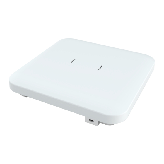
Introduction Extreme Networks AP-8432 internal antenna Access Point's are high-tier Access Points for dependable and efficient network performance. The Access Point’s unique WiNG 5 software enables the Access Point to function as either a Standalone Access Point, an Adaptive Access Point or a Virtual Controller. -
Page 6: Ap-8432 Package Contents
AP-8432 Package Contents • Verify cable lengths are within the maximum allowable distances for optimal signal transmission. AP-8432 Package Contents An AP-8432 Access Point is available in internal antenna configurations only. An AP-8432 ships with the following: • AP-8432 Access Point •... -
Page 7: Hardware Installation
Hardware Installation Installation Instructions An AP-8432 Access Point mounts either on a wall (with M 3.5 x 0.6 x 23 MM pan head screws and mounting bracket or equivalent) or on a suspended ceiling T-bar. To prepare for the installation: 1 Match the part number on the purchase order with the part numbers in the packing list and on the case of the Access Point. -
Page 8: Power Injector System
Access Point. Power Injector System An AP-8432 Access Point can receive power via an Ethernet cable connected to the GE1/ POE (LAN) port. When users purchase a WLAN solution, they often need to place Access Points in obscure locations. - Page 9 However, using the wrong solution (including a POE system used on a legacy Access Point) could either limit functionality or severely damage the Access Point and void the product warranty. A separate Power Injector is required for each AP-8432 Access Point comprising the network. AP-8432 Power Management...
-
Page 10: Wall Mount Instructions
Wall Mount Instructions A wall mount deployment requires hanging the AP-8432 with the provided mounting bracket and two screws. The AP-8432 can be mounted on to any plaster, wood or cement wall surface using the provided mounting bracket. The hardware required to install the AP-8432 on a wall consists of: •... - Page 11 Hardware Installation Wall Mount Procedure - New Installation This section describes a new AP-8432 installation with no previous Access Point existing on the intended wall surface. 1 Place the mounting bracket against the wall. 2 Mark the screw hole locations depending on the intended deployment orientation of the unit.
-
Page 12: Suspended Ceiling T-Bar Mount Instructions
Ceiling mount requires holding the AP-8432 up against the T-bar of a suspended ceiling grid and twisting the unit on to the T-bar. If deploying the AP-8432 on a sculpted ceiling T- Bar, the Access Point mounting kit (Part No. KT-135628-01) can optionally be used as well. - Page 13 Access Point and void the product warranty. Do not actually connect to the power source until the cabling portion of the installation is complete. 3 Verify the unit has power by observing the LEDs. For more information on AP-8432 LED behavior, see LED Indicators on page Align the bottom of the ceiling T-bar with the back of the Access Point.
-
Page 14: Led Indicators
7 Rotate the Access Point chassis 45 degrees counter-clockwise. The clips click as they fasten to the T-bar. The Access Point is ready to configure. LED Indicators The AP-8432 LED activity indicators are located on the top of the housing and are visible through the enclosure. AP-8432 Installation Guide... - Page 15 Sensor without SS connected Sensor with SS connected Air Termination Blinking 0.5 state second in 1 second duty cycle BT radio disabled BT radio enabled (operational) AP-8432 Installation Guide...
-
Page 16: Basic Access Point Configuration
Basic Access Point Configuration Basic Access Point Configuration Once the AP-8432 is installed and powered on, complete the following steps to get the Access Point up and running and access management functions: 1 The Access Point’s IP address is optimally provided using DHCP. A zero config IP address can also be derived if DHCP resources are unavailable. - Page 17 The first page of the Initial Setup Wizard displays the Navigation Panel and Function Highlights for the configuration activities comprising the Access Point's initial setup. This page also displays options to select the typical or advanced mode for the wizard. AP-8432 Installation Guide...
- Page 18 Initial Setup Wizard. 8 The Typical Setup Wizard displays the Access Point Settings screen to define the Access Point's Standalone versus Virtual Controller AP functionality. This screen also enables selection of the country of operation for the Access Point. AP-8432 Installation Guide...
- Page 19 Consequently, the two interfaces cannot be used collectively to manage profiles without encountering problems. 10 Select the Country Code of the country where the Access Point is deployed. Selecting a proper country is a critical task while configuring the Access Point, as it defines the AP-8432 Installation Guide...
- Page 20 When Bridge Mode is selected, WAN configuration cannot be performed and the Typical Setup Wizard does not display the WAN configuration screen. 14 Select Next . The Typical Setup Wizard displays the LAN Configuration screen to set the Access Point's LAN interface configuration. AP-8432 Installation Guide...
- Page 21 • Secondary DNS - Enter an IP Address for the backup Domain Name Server providing DNS services for the Access Point's LAN interface. 16 Select Next . The Typical Setup Wizard displays the Wireless LAN Setup screen to set the an Access Point's WLAN 1 and WLAN 2. AP-8432 Installation Guide...
- Page 22 Access Point and requesting clients. 18 Select Next . The Typical Setup Wizard displays the RADIUS Server Configuration screen if required. Otherwise, the Typical Setup Wizard displays the Summary and Commit screen. AP-8432 Installation Guide...
- Page 23 • Password - Provide a password to authenticate the user. • Confirm Password - Confirm the password by entering the same password entered in the Password field. • Description - Provide a description to identify the user created in the RADIUS server database. AP-8432 Installation Guide...
- Page 24 Access Point’s updated configuration before it’s deployed. However, if a screen displays settings not intended as part of the initial configuration, then any screen can be selected again from within the Navigation Panel and its settings modified accordingly. AP-8432 Installation Guide...
-
Page 25: Ap-8432 Access Point Specifications
Navigational Panel , or use the Back and Next buttons to scroll to the target screen. AP-8432 Access Point Specifications Electrical Characteristics An AP-8432 Access Point has the following electrical characteristics: Operating Current & 48VDC, 0.625A (AUX input voltage) Voltage 48VDC PWR-BGA48V45W0WW Power Supply 48VDC, 0.53A (POE) -
Page 26: Regulatory Information
Regulatory Information This guide applies to the following Model Numbers: AP-8432I. All Extreme Networks devices are designed to be compliant with the rules and regulations in the locations they are sold and will be labeled as required. Any changes or modifications to Extreme Networks equipment, not expressly approved by Extreme Networks could void the user's authority to operate the equipment. -
Page 27: Wireless Device Country Approvals
Declaration of Conformity in Languages of the European Community Hereby, Extreme Networks, Inc. declares that the radio equipment type Wireless LAN Access Point is in compliance with Directive 2014/53/EU. The full text of the EU declaration of conformity is available at the following Internet address: http://www.extremenetworks.com/... -
Page 28: Frequency Of Operation - Ic
You are reminded of the need to observe restrictions on the use of radio devices in fuel depots, chemical plants etc. and areas where the air contains chemicals or particles (such as grain, dust, or metal powders). AP-8432 Installation Guide... -
Page 29: Potentially Hazardous Atmospheres - Fixed Installations
If you have any reason to suspect that interference is taking place, turn OFF your device. Other Medical Devices Please consult your physician or the manufacturer of the medical device, to determine if the operation of your wireless product may interfere with the medical device. AP-8432 Installation Guide... -
Page 30: Rf Exposure Guidelines
Cet équipement est conforme aux limites d'exposition aux rayonnements IC établies pour un environnement non contrôlé. Cet équipement doit être installé et utilisé avec un minimum de 40cm de distance entre la source de rayonnement et votre corps. AP-8432 Installation Guide... -
Page 31: Power Supply
This device must be powered from a 802.3af or 802.3at compliant power source which has been certified by the appropriate agencies, or by a Extreme Networks approved UL LISTED ITE (IEC/EN 60950-1, LPS/SELV) power supply with electrical ratings: Output 48 Vdc 45 watts with a maximum ambient temperature rating of at least 50 degrees C. - Page 32 This radio transmitter (AP-8432) has been approved by Industry Canada to operate with the antenna types listed below and having a maximum gain allowable and the impedance required for each type of antenna.
-
Page 33: Ce Marking And European Economic Area (Eea)
Maximum radiated transmit power of 100 mW EIRP in the frequency range 2.400 - 2.4835 GHz. Statement of Compliance Extreme Networks hereby declares that this radio equipment is in compliance with Directive 2011/65/EU and 1999/5/EC or 2014/53/EU (2014/53/EU supersedes 1999/5/EC from 13th June 2017). -
Page 34: Other Countries
For more information consult the website www.anatel.gov.br. Nota: A marca de certificação se aplica ao Transceptor, modelo AP-8432. Este equipamento opera em caráter secundário, isto é, não tem direito a proteção contra interferência prejudicial, mesmo de estações do mesmo tipo, e não pode causar interferência a sistemas operando em caráter primário. - Page 35 о б м е ж е н н я щ о д о в и к о р и с т а н н я д е я к и х н е б е з п е ч н и х р е ч о в и н в е л е к т р и ч н и х т а е л е к т р о н н и х п р и с т р о я х . Thailand AP-8432 Installation Guide...
-
Page 36: Waste Electrical And Electronic Equipment (Weee)
4 It is the users’ responsibility to utilize the available collection system to ensure WEEE is properly treated. For information about the available collection system, please contact Extreme Customer Support at +353 61 705500 (Ireland). TURKISH WEEE Statement of Compliance EEE Yönetmeliğine Uygundur AP-8432 Installation Guide... -
Page 37: End-User Software License Agreement
In the case of Licensed Materials offered on a subscription basis, the term of “licensed use” shall be as defined within Your Ordering Documentation. 3 GRANT OF LICENSE. Extreme will grant You a non-transferable, non-sublicensable, non- exclusive license to use the Licensed Materials and the accompanying documentation for AP-8432 Installation Guide... - Page 38 6 RESTRICTION AGAINST COPYING OR MODIFYING LICENSED MATERIALS. Except as expressly permitted in this Agreement, You may not copy or otherwise reproduce the Licensed Materials. In no event does the limited copying or reproduction permitted AP-8432 Installation Guide...
- Page 39 Extreme at its request. Nothing herein shall limit your use or dissemination of information not actually derived from Extreme or of information which has been or subsequently is made public by Extreme, or a third party having authority to do so. AP-8432 Installation Guide...
- Page 40 United States regulation or statute (including but not limited to those countries embargoed from time to time by the United States government); or contrary to the laws or regulations of any other governmental entity that has jurisdiction over such export, import, transmission or Use. AP-8432 Installation Guide...
- Page 41 (an Open Source License). Your use, modification and redistribution of the Open Source Software are governed by the terms and conditions of the applicable Open Source License. More details regarding the Open AP-8432 Installation Guide...
- Page 42 Any notice or other communication to be sent to Extreme must be mailed by certified mail to the following address: Extreme Networks, Inc. 16480 Via Del San Jose, CA 95119 United States Tel: +1 408-579-2800 Toll-free: +1 888-257-3000 AP-8432 Installation Guide...
-
Page 43: Ap-8432 Access Point China Rohs Compliance
本表格依据 SJ/T 11364 的规定编制。 O: 表示该有害物质在该部件所有均质材料中的含量均在 GB/T 26572 规定的限量 要求以下。 X: 表示该有害物质至少在该部件的某一均质材料中的含量超出 GB/T 26572 规定 的限量要 求。 ( 企业可在此处,根据实际情况对上表中打 “×” 的技术原因进 行进一步说明。 ) This table was created to comply with China RoHS requirements for AP-8432 Access Points. AP-8432 Installation Guide...
Need help?
Do you have a question about the AP-8432 and is the answer not in the manual?
Questions and answers