Advertisement
Instruction Manual
Form 1292
October 1997
Types 655 and 655R Actuators
for Self-Operated Control
Contents
Introduction
. . . . . . . . . . . . . . . . . . . . . . . . . . . . . . .
Scope of Manual
. . . . . . . . . . . . . . . . . . . . . . . . . . . . .
Description
. . . . . . . . . . . . . . . . . . . . . . . . . . . . . . . . . .
Specifications
. . . . . . . . . . . . . . . . . . . . . . . . . . . . . . .
Installation
. . . . . . . . . . . . . . . . . . . . . . . . . . . . . . . .
Actuator Mounting
. . . . . . . . . . . . . . . . . . . . . . . . . . .
Loading Connections
. . . . . . . . . . . . . . . . . . . . . . . . .
Startup
. . . . . . . . . . . . . . . . . . . . . . . . . . . . . . . . . . . .
Startup for Pressure-Reducing Service
Startup for Pressure-Relief Service
Adjustment for Pressure-Reducing or
Pressure-Relief Service
Shutdown
. . . . . . . . . . . . . . . . . . . . . . . . . . . . . . . . .
Maintenance
. . . . . . . . . . . . . . . . . . . . . . . . . . . . . .
Actuator
. . . . . . . . . . . . . . . . . . . . . . . . . . . . . . . . . . . .
Disassembly
. . . . . . . . . . . . . . . . . . . . . . . . . . . . . . .
Assembly
. . . . . . . . . . . . . . . . . . . . . . . . . . . . . . . . . .
Top-Mounted Handwheel
Disassembly
. . . . . . . . . . . . . . . . . . . . . . . . . . . . . . .
Assembly
. . . . . . . . . . . . . . . . . . . . . . . . . . . . . . . . . .
Parts Ordering
. . . . . . . . . . . . . . . . . . . . . . . . . . . .
Parts List
. . . . . . . . . . . . . . . . . . . . . . . . . . . . . . . . .
Introduction
Scope of Manual
This instruction manual provides installation, adjust-
ment, maintenance, and parts ordering for the Type
655 and 655R actuators and the top-mounted hand-
wheel. Refer to separate instruction manuals for in-
formation about valves and accessories used with
these actuators.
Only personnel qualified through training or experience
should install, operate, and maintain the Type 655 and
655R actuators. If you have any questions about these
instructions, contact your Fisher Controls sales office
or sales representative before proceeding.
1
1
2
2
2
3
6
6
. . . . . . . . . .
6
. . . . . . . . . . . . .
6
. . . . . . . . . . . . . . . . . . . .
6
7
7
7
7
8
. . . . . . . . . . . . . . . . . . . . .
8
9
9
9
10
Type 655 and 655R
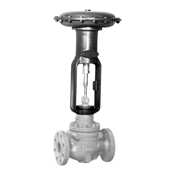
W0466-1 / IL
Figure 1. T ype 655-ED Pressure-Reducing V alve
1F9408-E / DOC
Figure 2. T ype 655 Actuator Nameplate
Advertisement
Table of Contents

Subscribe to Our Youtube Channel
Related Manuals for Fisher 655


Summary of Contents for Fisher 655
- Page 1 Figure 2. T ype 655 Actuator Nameplate Only personnel qualified through training or experience should install, operate, and maintain the Type 655 and 655R actuators. If you have any questions about these instructions, contact your Fisher Controls sales office...
-
Page 2: Form
(3 mm) for seating 44, 45, 46 Description Installation Type 655 and 655R actuators (figure 1) are pressure- WARNING actuated, spring-and-diaphragm actuators used in conjunction with various valves to provide control for a wide variety of pressure regulation applications. Type... -
Page 3: Actuator Mounting
Type 655 and 655R in the pipeline ahead of the regulator or relief valve to yoke to the mating shoulder on bonnet, and then protect it while in service. And a conventional three- add the valve plug travel to this measurement. - Page 4 Type 655 and 655R Table 2. Actuator Pressure-Setting Ranges PRESSURE PRESSURE PRESSURE PRESSURE REDUCTION RELIEF REDUCTION RELIEF ACTUATOR SPRING PART ACTUATOR SPRING PART ACTUATOR SPRING PART ACTUATOR SPRING PART Minimum Maximum Minimum Maximum Minimum Maximum Minimum Maximum SIZE SIZE NUMBER...
- Page 5 Type 655 and 655R Table 3. Effective Diaphragm Area TRAVEL DOWN FROM UPPER CASING STOP, IN. (mm) ACTUATOR ACTUATOR 1/8 (3) 3/16 (5) 1/4 (6) 3/8 (10) 7/16 (11) 1/2 (13) 9/16 (14) 3/4 (19) 7/8 (22) SIZE SIZE 3A, 4A 10.2...
-
Page 6: Loading Connections
Type 655 and 655R g. Lower the actuator onto the valve body bonnet, Startup and tighten the yoke locknut. The procedures for placing into operation and adjust- ing the equipment for both pressure-reducing and h. Stroke the actuator, and measure the stem pressure-relief applications are described below. -
Page 7: Shutdown
Type 655 and 655R Disassembly 3. Replace the spring and reassemble the actuator by following steps 5 and 6 of the Assembly portion of the Maintenance section. CAUTION In the following procedure, do not rotate the valve plug while it is seated since... -
Page 8: Assembly
Type 655 and 655R e. Rotate the entire actuator until the actuator have enough slack inside the casings for stem disengages from the valve plug stem. efficient travel. 5. Secure the diaphragm plate (key 4) to the actuator 3. Turn the adjusting screw (key 10) counterclockwise... -
Page 9: Disassembly
(key 31, not shown; key 2. Loosen the hex nut (key 27, figures 6 and 7; key 140, figure 8). For Type 655, size 3B and 4B actua- 137, figure 8). Turn the adjusting screw (key 10, figure tors, a travel stop (key 34, figure 7) should also be in- 5) and the handwheel (key 25, figures 6 and 7;... - Page 10 Type 655 and 655R Description Part Number Parts List Diaphragm Plate (Continued) Sizes 3B & 4B Type 655 1F725619042 Type 655R Actuator 7/16 in. (11 mm) travel 1F725819042 5/8 in. (16 mm) travel 1F725719042 Description Part Number 3/4 in. (19 mm) travel 1F725619042 Sizes 32 &...
- Page 11 1A560632982 All other sizes (quantity req’d same as key 19) 1A346524122 Travel Stop, steel (not shown) Cap Screw, cd pl steel Sizes 3B & 4B, Type 655 only 1J833124092 Sizes 3B & 4B (6 req’d) 1A560632982 All other sizes Sizes 32 thru 46 W/o travel stops (6 req’d)
- Page 12 Type 655 and 655R 30A8342-A/DOC 30A8341-A/DOC APPLY MOLYKOTE NO. 77 LUBRICANT TO ADJUSTING SCREW Figure 5. T ype 655 Actuator APPLY LUB APPLY LUB PART NOT SHOWN : 31 PARTS NOT SHOWN : 30 & 31 28A1216-C/DOC 38A1217-B/DOC Figure 6. Size 3A and 4A T op-Mounted Figure 7.
- Page 13 Type 655 and 655R BV8008-E/DOC Figure 8. Size 32 through 46 T op-Mounted Handwheel Assembly . Key 6 Spring, steel SPRING RATE SAFE LOAD SPRING SPRING COLOR CODE COLOR CODE PART NUMBER Lb/in. N/mm Aluminum & red 1F713027112 1290 1F714427112 Aluminum &...
- Page 14 Type 655 and 655R Fisher, Fisher-Rosemount, and Managing The Process Better are marks owned by Fisher Controls International, Inc. or Fisher-Rosemount Systems, Inc. All other marks are the property of their respective owners. Fisher Controls International, Inc. 1975, 1997; All Rights Reserved...
Need help?
Do you have a question about the 655 and is the answer not in the manual?
Questions and answers