Table of Contents
Advertisement
Quick Links
PCL-725
Relay Actuator and Isolated D/I Card
USER'S MANUAL
COPYRIGHT NOTICE
This documentation is copyrighted 1989 by Advantech Co.,
Ltd. All rights are reserved. Advantech Co., Ltd. Reserves
the right to make improvements in the products described
in this manual at any time without notice.
No part of this manual may be reproduced, copied,
translated or transmitted in any form or by any means
without the prior written permission of Advantech Co., Ltd.
Information provided in this manual is intended to be
accurate and reliable. However, Advantech Co., Ltd.
assumes no responsibility for its use, nor for any
infringements of the rights of third parties which may result
from its use.
ACKNOWLEDGEMENTS
PC-LabCard is a trademark of Advantech Co., Ltd.
IBM and PC are trademarks of International Business
Machines Corporation.
MS-DOS is a trademark of Microsoft Corporation.
BASIC is a trademark of Dartmouth College.
Inter is a trademark of Intel Corporation.
Part No. 2003072500 4th Edition
Printed in Taiwan
Sept. 1995
Advertisement
Table of Contents

Related Manuals for Advantech PCL-725


Summary of Contents for Advantech PCL-725
- Page 1 USER'S MANUAL COPYRIGHT NOTICE This documentation is copyrighted 1989 by Advantech Co., Ltd. All rights are reserved. Advantech Co., Ltd. Reserves the right to make improvements in the products described in this manual at any time without notice. No part of this manual may be reproduced, copied, translated or transmitted in any form or by any means without the prior written permission of Advantech Co., Ltd.
-
Page 2: Table Of Contents
2.4. Jumpers ..........7 2.5. Installing The PCL-725 ....... . .8 CHAPTER3. -
Page 3: Chapter 1. Introduction
When read, the data results reflect the state of the signals on the wires. Designed with this idea in mind, the PCL-725 Relay Actuator & Isolated D/I card is an IBM PC add-on card that offers you 8 relay actuators and 8 opto- isolated digital inputs on a single board. -
Page 4: Features, Application And Specifications
PCL-725 Introduction 1.2. Features, Application and Specifications Features : * 8 Relay actuator outputs. * 8 Opto-isolated digital inputs. * LED indicators to show activated relays. * Jumper selectable isolated/non-isolated input signals. * On-board relay driver circuits. * On-board input signal conditioning circuits. - Page 5 Introduction PCL-725 Specifications: * Isolated Digital Input Opto-isolator: 4N25 Input channels: Input current: 60 MA max for isolated input. Input buffered by voltage comparator Input voltage: 5-24VDC Input impedance: 560 Ohm/W Threshold voltage: 1.5 VDC, adjustable by changing voltage dividing resistors...
- Page 6 Introduction PCL-725 * General Dimensions : 5 3/4" x 3 3/4" (14.7 cm x 9.5 cm.) Bus : IBM PC bus. Slot : One 62-pin slot. I/O port Address : Hex 200 - hex 3F8.
-
Page 7: Chapter2. Installation
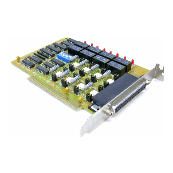
I/O port address space of the 8088 or 80286 microcomputer. The I/O port base address for the PCL-725 is selectable by an 8 position DIP switch. Valid addresses are from hex 200 to hex 3FE. Refer to Figure 2.1 for the... - Page 8 PCL- 725 Installation Figure 2.1 The PCL-725 Card The required switch settings for various base addresses are illustrated as below : Note : ON = 0. OFF = 1 "X" means "don't care" 1..8 are switch positions A1..A8 correspond to address lines of the PC bus. A9 is hard-wired to be 1.
-
Page 9: Connectorpin Assignments
3FE-3FF 2.3. Connector Pin Assignments The PCL-725 card is equipped with a 37 pin D type connector accessible from the rear plate. Please refer to Figure 2.1 for the location of the connector. The following diagram below shows its pin assignments. -
Page 10: Jumpers
PCL-725 Installation NO 0 20 . COM 0 21 . COM 3 22 . 23 . COM 1 24 . COM 4 25 . 26 . COM 6 COM 2 27 . 28 . COM 6 29 . COM 7 30 . -
Page 11: Installing The Pcl-725
Slide the system unit's cover away from the rear and to the front. When the cover will go no further, tilt it up, remove it from the base, and set it aside. The PCL-725 is configured at the factory for the IBM PC, PC/XT, PC/AT and all IBM PC compatibles. - Page 12 PCL-725 Installation cable to the connector. Slide the system unit's cover back on. Align the system unit tabs with the cover holes and reinstall the 1/4 mounting screws.
-
Page 13: Chapter3. Digital I/O Programming
CHAPTER 3. DIGITAL I/O PROGRAMMING On the PCL-725 card, 8 digital input channels and 8 relay output channels are provided. Two I/O port addresses (started from BASE +0) are reserved for accessing these channels. The two addresses are allocated as :... -
Page 14: Chapter 4. Customize The Current Limit Resistor
CHAPTER 4. CUSTOMIZE THE CURRENT LIMIT RESISTOR The default voltage input range of the PCL-725 is from 0V to 24V. To accept higher voltage input, users can replace the current limit resistors, RAO through RA7, for each channel. It is easy to choose the proper current limit resistor. Since the 4N25 isolator has a current rating of 60 mA, your input current can not exceed 60 mA. -
Page 15: Chapter5. Relay Output
CHAPTER 5. RELAY OUTPUT After power on, the initial relay output status of the PCL-725 is shown as below: Fig. 5-1 A write operation to I/O address, BASE+O, will change the output status of each relay. For example, if Bit 0 of BASE+0 is set as "1" (logic high), relay 0, K0, will switch from position "NORMAL CLOSE", NC0, to position "NORMAL... -
Page 16: Using The Contactprotection Nomograph
12 V @ 65 mA. Figure 5-2 illustrates an example of a relay contact protection network. For instance, if the load to be switched is 50 V @ 300 mA, then R = 56 ohms and C = 0.009 uF (remember that, for PCL-725's relay output, E = 120 V maximum). - Page 17 PCL-725 Relay Output Figure 5-3...
-
Page 18: Appendixa. I/Oport Address Map
Appendix A. I/O Port Address Map I/O address Uses range (Hex) --------------------------------------------------------------- 000-1FF Used by base system board Not used Game control 202-277 Not used 278-27F Second printer port 280-2F7 Not used 2F8-2FF COM2 300-377 Not used 378-37F Printer port 380-3AF Not used 3B0-3BF...
Need help?
Do you have a question about the PCL-725 and is the answer not in the manual?
Questions and answers