Kenwood KIV-700 Service Manual
Digital media receiver
Hide thumbs
Also See for KIV-700:
- Instruction manual (77 pages) ,
- Quick start manual (60 pages) ,
- Quick start manual (15 pages)
Table of Contents
Advertisement
Quick Links
DIGITAL MEDIA RECEIVER
KIV-700
KIV-BT900
SERVICE MANUAL
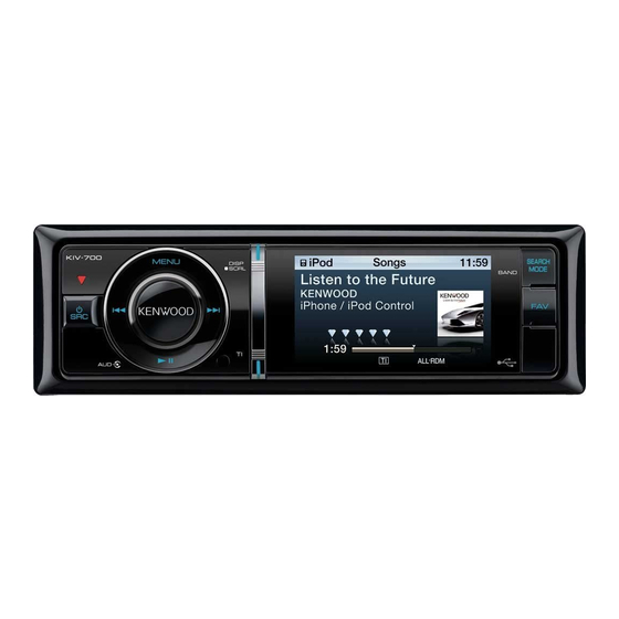
Panel assy
KIV-700 (K) (A64-5140-01)
Panel assy
KIV-700 (E) (A64-5141-01)
Mounting hardware assy
(J22-0789-03)
* Screw set
(N99-1757-15)
* DC cord
(E30-6940-05)
* Depends on the model. Refer to the parts list.
Escutcheon
(B07-3245-01)
Lever
Connecting cord assy
(D10-7106-04) x2
(E30-6920-05)
* DC cord
(E30-6939-05)
© 2010-5 PRINTED IN JA PAN
B53-0805-00 ( N ) 306
Panel assy
KIV-700 (M) (A64-5142-01)
Panel assy
KIV-BT900 (K) (A64-5139-01)
* Compact disc
* Remote controller assy (RC-405)
(W01-1780-05)
(A70-2104-05)
Cord with connector
(E30-6958-05)
This product complies with the
* Microphone
(W01-1768-05)
This product uses Lead Free solder.
RoHS
directive for the European market.
Advertisement
Table of Contents

Related Manuals for Kenwood KIV-700


Summary of Contents for Kenwood KIV-700
-
Page 1: Service Manual
DIGITAL MEDIA RECEIVER KIV-700 KIV-BT900 SERVICE MANUAL © 2010-5 PRINTED IN JA PAN B53-0805-00 ( N ) 306 Panel assy Panel assy KIV-700 (K) (A64-5140-01) KIV-700 (M) (A64-5142-01) Panel assy Panel assy KIV-700 (E) (A64-5141-01) KIV-BT900 (K) (A64-5139-01) * Compact disc Escutcheon... - Page 2 ELECTRIC UNIT ∗ Q80-83 (X34- ) (A/2) 4V PRE+B Q440,442,450,451,460,462 IC240 P.ON J420 PRE OUT A480 Q480,481 MUTE (F/R/SW) AM+B IC201 FRONT-END J400 IC451 POWER SP OUT LX BUS (FL/FR/RL/RR) P.ON5V OFFSET E2PROM FM/AM MUTE STBY MD(BT) E-VOL Q90,93 BU/SURGE IC300 BACK UP WININ...
-
Page 3: Components Description
KIV-700/BT900 COMPONENTS DESCRIPTION ● SWITCH UNIT (X16-6880-10) Ref. No. Application / Function Operation / Condition / Compatibility Remote Controller Outputs remote control signal when IR signal is received. Triangle RED Driver When the base turns on, D1 is turned on. - Page 4 KIV-700/BT900 COMPONENTS DESCRIPTION Ref. No. Application / Function Operation / Condition / Compatibility IC303 Mute Logic Controls logic for muting. IC304 Reset Logic Logic for reset (SRC/MENU/AUDIO). IC451 E-VOL & Source Selector Controls the source and volume. IC500 RDS Decoder RDBS and RDS decoder.
-
Page 5: Microcomputer's Terminal Description
SRC KEY Source key input H: OFF, L: ON MENU KEY Menu key input H: OFF, L: ON KENWOOD KEY KENWOOD key (Rotary push) input H: OFF, L: ON 24,25 Not used Output L fi xed PWIC BEEP Beep output... - Page 6 ACC found: L, No ACC: H ILLUMI DET Dimmer illumination detection L: ON, H: OFF VCC2 Not used Output L fi xed KIV-700 TEL mute: Below 1V, NAVI LINE MUTE Line mute detection mute: Over 2.5V KIV-BT900 NAVI mute: Over 2.5V DSP PDN DSP reset...
- Page 7 KIV-700/BT900 MICROCOMPUTER’S TERMINAL DESCRIPTION Truth Pin No. Pin Name Application Processing / Operation / Description Value Table SDA EVOL SDA I/O Data output from system u-com to E-VOL SCL DSP SCL I/O I2C clock for DSP SCL E2P SCL I/O I2C clock for the mother E2PROM SCL EVOL SCL I/O Clock output from system μ-com to E-VOL...
- Page 8 KIV-700/BT900 MICROCOMPUTER’S TERMINAL DESCRIPTION Truth value table q FSEL terminal switch (AM) [FSEL_5V] Pin36 μ-com terminal 1110kHz~1700kHz 530kHz~1100kHz Reception frequency (Destination “K”) 1107kHz~1611kHz 531kHz~1098kHz Channel space switching 1107kHz~1611kHz 531kHz~1098kHz Reception frequency (Destination “M” & “E”) 1110kHz~1700kHz 530kHz~1100kHz Channel space switching Reception frequency (Destination “J”)
-
Page 9: Test Mode
KIV-700/BT900 TEST MODE ■ Key layout ∗ The product can be reset by simultaneously pressing the following three keys: [MENU], [AUD] and [SRC]. MENU DISP SEARCH MODE Play/Pause TEL or TI or PLAY MODE ■ How to transfer into the test mode Press and hold the [TEL] or [TI] or [PLAY MODE] and [FAV] keys and reset. - Page 10 KIV-700/BT900 TEST MODE ■ Information display while all the lights are turned on The following information shall be displayed when the key listed in the next table is pressed while all the lights are turned on in STANDBY source. Press this key briefl y: To transfer to Software version & various service information display mode.
- Page 11 [DISP] S Y S _ R O M _ R 1 2 3 ∗ Press this Ex. In the case of the model without the built-in BT (KIV-700) key briefl y S Y S 0 2 – 1 . 2...
- Page 12 KIV-700/BT900 TEST MODE • POWER ON time display · Image of display P o n T i m _ 0 H x x _ x x x x x (Remote (In the “xx”, the fi gure between 00 and 50 (00~50) shall be displayed. When it is less than 1 hour, it shall be dis- controller) played rounded up/down to 10 minutes.)
- Page 13 KIV-700/BT900 TEST MODE Only in E type, switch frequency to LW-216kHz by pressing [2] key or [FAV] key briefl y in TUNER AM band. In the model for all destinations, switch Band by pressing [SEARCH MODE] key briefl y in TUNER source.
- Page 14 KIV-700/BT900 TEST MODE Seek stop level manual adjustment mode • Image of display (In the case of Normal [Local OFF]) M N N _ 3 . 9 8 V (In the case of Local [Local ON]) M N L _ 4 . 4 4 V The value saved in E2PROM as the default value is displayed.
- Page 15 KIV-700/BT900 TEST MODE ■ BT mode test mode (KIV-BT900) The internal LOOPBACK function is available only in the model with the built-in BT. ∗ After switching into the BT mode (BT SRC) with TEL, follow the next steps of operations: Press and hold this key: To enter the internal LOOPBACK mode ∗...
- Page 16 KIV-700/BT900 TEST MODE ■ Menu list adjust mode Press [MENU] key briefl y to display the Menu list. Press [DNPP/SBF] and [DIRECT] key on the remote controller to transfer into the Menu list mode. You shall not use the remote controller to successively send the items.
- Page 17 KIV-700/BT900 TEST MODE ■ ROM correction (system μ-com) update functional specifi cation While keeping pressing [SEARCH MODE] and [Play/Pause] keys, operate reset and BU ON to transfer into this mode. Procedure Display Description Reset and BU ON operation (Display lights up)
- Page 18 KIV-700/BT900 INSTALLER MEMORY SPECIFICATIONS At specialists (or specialty stores), when the installer sends source in which the saving operation was carried out is the vehicle back to the user, they may make the store-rec- saved as such.) ommended audio confi guration.
- Page 19 KIV-700/BT900 PC BOARD PC BOARD (COMPONENT SIDE VIEW) (FOIL SIDE VIEW) SWITCH UNIT SWITCH UNIT X16-6880-10 (J76-0698-02) X16-6880-10 (J76-0698-02) TP18 TP19 TP13 TP12 TP11 TP16 TP15 TP14 TP17 TP25 TP21 TP23 TP20 TP24 TP22 TP26 TP27 TP10 TP28 TP29 D14 D13...
-
Page 20: Pc Board (Component Side View)
KIV-700/BT900 PC BOARD (COMPONENT SIDE VIEW) PROCESSOR UNIT X17-2080-10 (J76-0700-12) CN201 CN601 R414 R416 CP601 R415 CP604 D404 D403 CP55 CP54 CP53 C104 CP52 C107 CP51 C103 C102 C156 C153 C152 C151 D402 D401 L401 R403 R404 IC100 R332 D411... - Page 21 KIV-700/BT900 PC BOARD (FOIL SIDE VIEW) PROCESSOR UNIT X17-2080-10 (J76-0700-12) Q421 R421 R419 C204 C213 IC402 CP89 CP88 C142 IC202 IC51 R426 C143 R429 R430 C214 IC71 IC61 CP23 CP20 IC103 CP19 CP18 CP17 R529 CP86 R528 C121 R530 R103...
-
Page 22: Electric Unit
KIV-700/BT900 PC BOARD (COMPONENT SIDE VIEW) ELECTRIC UNIT X34-677x-xx A/2 (J76-0699-12) J400 AUX OUT IC201 PRE OUT 13 11 12 8 4 3 J470 9 10 6 J420 C225 C227 R205 C474 R472 D209 C206 C226 R476 C224 D201 R474... - Page 23 KIV-700/BT900 X34-677x-xx Ref. No. Address IC10 IC20 IC70 IC170 X34 B/2 IC171 IC10 IC201 R737 IC240 R731 R732 D704 IC300 C758 IC301 R736 C757 IC302 Q707 IC303 R734 IC304 D702 D714 IC451 Q706 D715 IC500 C762 Q130 IC551 C761 R718...
- Page 24 KIV-700/BT900 PC BOARD (FOIL SIDE VIEW) ELECTRIC UNIT X34-677x-xx A/2 (J76-0699-12) C216 TP204 TP19 X34 B/2 TP734 TP733 TP308 C764 TP21 TP739 TP737 R741 TP729 TP738 R740 R726 C763 TP728 Q114 TP736 Q113 D710 TP735 TP732 TP731 TP724 TP730 D709...
- Page 25 KIV-700/BT900 X34-677x-xx C207 C216 C204 Ref. No. Address C462 C442 C452 C461 C441 C451 R475 C473 R452 R463 R443 R453 R462 R442 Q110 R485 R420 Q111 D480 Q112 Q113 Q114 Q115 L483 Q480 R483 C247 Q481 C246 R482 R480 C245...
- Page 26 KIV-700/BT900 J400 5L I/F PRE OUT REAR AUX IN FRONT ELECTRIC UNIT (X34-677x-xx) (A/2) J470 J420 Q440,442,450,451,460,462 PRE-OUT R471 MUTE SW TP473 R473 R475 C404 0.01 (+REAR) FRONT REAR R442 R443 R452 R453 R462 R463 Q440 Q442 Q450 Q451 Q460...
- Page 27 KIV-700/BT900 POWER IC TP204 R213 4V-PRE C204 D200 IC201 6.6V 5.0V R325 100K IC301 RESET C306 0.01 C316 R323 R321 3.3V R300 2.2M R315 2.2K TP625 WIRED PANEL REMO TP306 RDS QUAL TP201 BYTE R302 CNVSS C302 32.768kHz XCIN X301...
- Page 28 KIV-700/BT900 E2PROM ∗ IC300 4V-PRE 4V-PRE 5.0V BU5V 5.0V C304 0.01 IC10 TP21 AUD8 ∗ TP80 0-5.0V ∗ 4V-PRE +B TP23 1000P A5V REG SDA DSP SDA IC20 TP22 SDA E2P SDA SDA EVOL SDA 5.0V LX REQ M R304...
- Page 29 • DC voltages are as measured with a high impedance volt me ter. Val ues may vary slight ly due to vari a tions between in di vid u al in- stru ments or/and units. KIV-700/BT900 (1/4) X34-677x-xx A/2 (4/4)
- Page 30 FREQ of IC700 TP702 KIV-700/BT900 (2/4) CAUTION : For continued safety, re place safe ty critical com po nents only with manufacturer’s rec om mend ed parts (refer to parts list). Indicates safety critical com po nents. To reduce the risk of electric shock, leakage-cur rent or re sis tance mea sure ments shall be carried out (ex posed parts are ac cept ably in su lat ed from the supply cir cuit) be fore the ap pli ance is returned to the customer.
- Page 31 KIV-700/BT900 PROCESSOR UNIT (X17-2080-10) CN201 HI-SIDE SW VBUS5V D3.3V R401 TP438 TP403 i-Pod IC401 AUTHENTICATION R402 TP439 VOUT USB GND TP404 POWER CP605 R427 TP451 TP450 I2CSCL CN502 NRESET TP447 R428 IC402 TP445 I2CSDA VGND MODE0 MODE1 VGND R341 TP421...
- Page 32 KIV-700/BT900 LCDPON LCDPON LCDPON D1.2V-3 D1.2V-3 D1.2V-3 D1.2V-2 D1.2V-2 D1.2V-2 D1.2V-1 D1.2V-1 D1.2V-1 CP605 22 TP451 TP450 TP447 TP445 D3.3V-1 D3.3V-1 D3.3V-1 CP603 22 TP444 TP446 TP448 TP449 CP601 u-COM IPOD DAI MCLK I2CO SCL VSSCO8 NC(DAI SDI) ZDET OUT...
- Page 33 KIV-700/BT900 LCDPON LCDPON LCDPON D1.2V-3 D1.2V-3 D1.2V-2 D1.2V-1 MEMORY for IC1 C102 CP51 22 12.000MHz D3.3V-1 D3.3V-1 5.1M CP52 22 C103 CP6 22 C104 CP5 22 CP53 22 DAI LRCL VDD12 VDD12 USB VDD33 IOUSB DQM0 CP4 22 DAI BCLK...
- Page 34 R514 47 L508 R515 47 L507 VSS1 VDD3 R516 47 L506 C115 R517 47 L505 R518 47 L504 D3.3V-2 R519 47 L503 R520 47 L502 D3.3V R521 47 L501 SOC PGND SHIELD GND D3.3V D3.3V LCDPON KIV-700/BT900 (3/4) X17-2080-10 (4/4)
- Page 35 CN72 : DA204U : FTZ6.8E KIV-700/BT900 (4/4) D16-18 : UDZW6.8(B) CAUTION : For continued safety, re place safe ty critical com po nents only with manufacturer’s rec om mend ed parts (refer to parts list). Indicates safety critical com po nents. To reduce the risk of electric shock, leakage-cur rent or re sis tance mea sure ments shall be car- ried out (ex posed parts are ac cept ably in su lat ed from the supply cir cuit) be fore the ap pli ance is returned to the customer.
-
Page 36: Exploded View
KIV-700/BT900 EXPLODED VIEW 291 (X34-:ELECTRIC UNIT) On bottom of IC700 there is a soldering part. Therefore replacement of IC700 is impossible. When needing replacement of IC700, “291” can be replaced. (X34-) IC700 (X34-) (B/2) : N09-6492-05 (X17-) : N09-6758-05 (X17-) -
Page 37: Parts List
3A ✽ K28-0422-14 KNOB ASSY (KENWOOD) W1 -9 R92-2053-05 CHIP R 0 OHM J 1/8W K: KIV-BT900 K1: KIV-700 M1: KIV-700 E1: KIV-700 Indicates safety critical com po nents. K : North America M : Other Areas) (E : Europe... - Page 38 CHIP R J 1/16W C401 CK73GB1H104K CHIP C 0.10UF R301 RK73GB2A300J CHIP R J 1/10W K: KIV-BT900 K1: KIV-700 M1: KIV-700 E1: KIV-700 Indicates safety critical com po nents. K : North America M : Other Areas) (E : Europe...
- Page 39 10UF C335 CK73GB1H104K CHIP C 0.10UF C90-6851-05 ELECTRO 220UF 25WV C336,337 CK73GB0J475K CHIP C 4.7UF K: KIV-BT900 K1: KIV-700 M1: KIV-700 E1: KIV-700 Indicates safety critical com po nents. K : North America M : Other Areas) (E : Europe...
- Page 40 CHIP R 4.3K J 1/10W C754 CC73GCH1H101J CHIP C 100PF RK73GB2A562J CHIP R 5.6K J 1/10W K: KIV-BT900 K1: KIV-700 M1: KIV-700 E1: KIV-700 Indicates safety critical com po nents. K : North America M : Other Areas) (E : Europe...
- Page 41 J 1/10W R333 RK73GB2A104J CHIP R 100K J 1/10W R553,554 RK73GB2A104J CHIP R 100K J 1/10W K: KIV-BT900 K1: KIV-700 M1: KIV-700 E1: KIV-700 Indicates safety critical com po nents. K : North America M : Other Areas) (E : Europe...
- Page 42 RKZ6.8KG(B2) ZENER DIODE Q366 RT1N144M-T111 TRANSISTOR D441 MC2846-T111 DIODE Q440 RT1N430M-T111 TRANSISTOR Q441 RT1P241M-T111 TRANSISTOR K: KIV-BT900 K1: KIV-700 M1: KIV-700 E1: KIV-700 Indicates safety critical com po nents. K : North America M : Other Areas) (E : Europe...
- Page 43 POSITIVE RESISTOR A900 W02-5374-05 ELECTRIC CIRCUIT MODULE A480 X86-4032-70 FRONT-END UNIT A480 X86-4230-11 FRONT-END UNIT KK1M1 K: KIV-BT900 K1: KIV-700 M1: KIV-700 E1: KIV-700 Indicates safety critical com po nents. K : North America M : Other Areas) (E : Europe...
-
Page 44: Specifications
Weight ............2.6 lbs (1.20kg) Output power ..+4dBm (MAX), 0dBm (AVE), Power Class 2 Maximum communication range KENWOOD follows a policy of continuous advancements ........Line of sight approx. 10m (32.8ft) in development. For this reason specifications may be Profi le ..........HFP (Hands Free Profi le), changed without notice.
Need help?
Do you have a question about the KIV-700 and is the answer not in the manual?
Questions and answers