
Related Manuals for Hioki FT6031


Summary of Contents for Hioki FT6031
- Page 1 FT6031 Instruction Manual EARTH TESTER Oct. 2018 Revised edition 2 FT6031A981-02 18-10H GlobalTestSupply www. .com Find Quality Products Online at: sales@GlobalTestSupply.com...
-
Page 2: Table Of Contents
Contents Introduction .................1 Verifying Package Contents ..........1 Options (sold separately) ..........2 Safety Notes ................3 Usage Notes ................8 Overview Overview and Features .........13 Overview ..............13 Features ..............13 Parts Names and Functions ......15 How to Use Carrying Case ......20 How to Measure 2.1 Measurement Workflow ........21 Attaching/Removing Protector ....24 Inserting/Replacing Batteries ......25... - Page 3 2.7 Simplified Measurement for Earth Resistance(Simplified Measurement Method, Two-pole Method) ......44 Performing zero adjustment ........46 Connecting test leads ..........48 Measuring earth resistance ........51 Stowing ..............51 Cautions and Tips for Measurement ...52 Distance between earthing electrodes ...... 52 Location to install auxiliary earthing rod ....53 How to insert / pull out auxiliary earthing rod ....
-
Page 4: Introduction
Introduction Introduction Thank you for purchasing the HIOKI FT6031 Earth Tester. To obtain maximum performance from the product, please read this manual first, and keep it handy for future reference. Verifying Package Contents When you receive the instrument, inspect it carefully to ensure that no damage occurred during shipping. -
Page 5: Options (Sold Separately)
Options (sold separately) Options (sold separately) The following options are available for the instrument. Contact your authorized Hioki distributor or reseller when ordering. L9787 Test Lead (for simplified measurement method, indoor use only, red and black 1.2 m each) L9840... -
Page 6: Safety Notes
Safety Notes Safety Notes This instrument is designed to conform to IEC 61010 Safety Standards, and has been thoroughly tested for safety prior to shipment. However, using the instrument in a way not described in this manual may negate the provided safety features. Before using the instrument, be certain to carefully read the following safety notes. - Page 7 Safety Notes Notation In this manual, the risk seriousness and the hazard levels are classified as follows. Indicates an imminently hazardous situation DANGER that will result in death or serious injury to the operator. Indicates a potentially hazardous situation WARNING that may result in death or serious injury to the operator.
- Page 8 Safety Notes Symbols affixed to the instrument Indicates cautions and hazards. When the symbol is printed on the instrument, refer to a corresponding topic in the Instruction Manual. Indicates a double-insulated device. Indicates DC (Direct Current). Indicates AC (Alternating Current). Indicates the power switch mark.
- Page 9 Safety Notes Screen display This instrument uses the following screen displays. A B C D E F G H I J K L M N O P Q R S T U V W X Y Z 1 2 3 4 5 6 7 8 9 0 Accuracy We define measurement tolerances in terms of f.s.
- Page 10 Safety Notes Measurement categories To ensure safe operation of measuring instruments, IEC 61010 establishes safety standards for various electrical environments, categorized as CAT II to CAT IV, and called measurement categories. DANGER • Using a measuring instrument in an environment designated with a higher-numbered category than that for which the instrument is rated could result in a severe accident, and must be carefully avoided.
-
Page 11: Usage Notes
Verifying before usage Before using the instrument, verify that it operates normally to ensure that no damage occurred during storage or shipping. If you find any damage, contact your authorized Hioki distributor or reseller. DANGER Before using the instrument, check that the coating of the test leads and cables are neither ripped nor torn and that no metal parts are exposed. - Page 12 Usage Notes Use environment of the device The protection rating for the enclosure of this device (based on EN60529) is *IP65/67. CAUTION Although this device has a dust-proof, jet-proof and water- proof structure, it is not for completely shutting out the water intrusion into the inside.
- Page 13 Usage Notes For details on the operating temperature and humidity, see the specifications. (p. 59) CAUTION • Installing the instrument in inappropriate locations may cause a malfunction of instrument or may give rise to an accident. Avoid the following locations. •...
- Page 14 Usage Notes Handling the cables CAUTION • To prevent cable damage, do not step on cables or pinch them between other objects. Do not bend or pull on cables at their base. • The ends of the L9787 Test lead and L9840 Auxiliary earthing rod are sharp.
-
Page 15: Overview
1 Overview Overview 1.1 Overview and Features Overview The grounding works applied to the distribution lines and electrical facilities are essential for preventing electric shock and fire as well as for safeguarding the equipment. This instrument is an earth tester that is fully functional for measuring earth resistance for grounding works. - Page 16 Overview and Features Dust-proof, The instrument can withstand water at a jet-proof and water- depth of 1 m for 30 minutes. proof The instrument is supplied with a useful Supplied with a winder so that it can be easily prepared and winder packed up before/after measurement.
-
Page 17: Parts Names And Functions
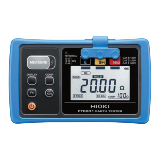
Parts Names and Functions 1.2 Parts Names and Functions Front Protector Measurement terminals Removed when Connected with the black cable. replacing the batteries. S(P) Connected with the yellow cable. (p. 2 4, p. 6 8) H(C) Connected with the red cable. Display Operation buttons... - Page 18 Rear and Sides Waterproof seal It needs to be replaced when degraded. Battery cover (side view) Please contact your authorized Hioki distributor. Battery cover Removed when replacing the batteries. (p. 2 5) Serial number label Please do not remove the label as it is needed for product control such as product warranty etc.
- Page 19 Parts Names and Functions Start/stop for measuring earth resistance • Displays the resistance of each earthing electrode. (p. 3 9) • Display switching (three-pole method, two-pole method) • DC/AC switching (when measuring earth potential) • Function switching (three-pole method, two-pole method) •...
- Page 20 Parts Names and Functions Display GlobalTestSupply www. .com Find Quality Products Online at: sales@GlobalTestSupply.com...
- Page 21 Parts Names and Functions Comparator Displays the battery comparison result level. (p. 2 7) (PASS) Displayed 30 sec. before Comparator auto-power-save function comparison result is activated. (p. 5 6) (FAIL) Indicates the terminal Lights up when DC/ to be connected with AC auto-detect measurement cable or setting is enabled...
-
Page 22: How To Use Carrying Case
How to Use Carrying Case 1.3 How to Use Carrying Case Please store the device, winder and other accessories/options into the C0106 Carrying Case as shown in the figure below. • Please do not store commercially available pegs in this carrying case as those have sharp tips. -
Page 23: How To Measure
2 How to Measure How to Measure 2.1 Measurement Workflow Before using the instrument, be sure to read “Usage Notes” (p.8). Preparation Insert the batteries. (p.25) As necessary, have other optional items available and Perform the startup check. (p.29) ready. Measurement Turn the power on and select the measurement method. - Page 24 Measurement Workflow DANGER • This product should only be connected to the secondary side of a breaker, so the breaker can prevent an accident if a short circuit occurs. Connections should never be made to the primary side of a breaker, because unrestricted current flow could cause a serious accident if a short circuit occurs.
- Page 25 Measurement Workflow WARNING • To prevent electric shock, confirm that the white or red portion (insulation layer) inside the cable of L9787 test lead and L9844 measurement cable are not exposed. If a color inside the cable is exposed, do not use the cable. CAUTION •...
-
Page 26: Attaching/Removing Protector
Attaching/Removing Protector 2.2 Attaching/Removing Protector Attaching the protector Tilt the device and slide it into the protector, and then push the entire device into the protector. Removing the protector Hold it with both hands and push the one end of the protector down. IMPORTANT If the protector is removed, drop-proof (p.60) will be void. -
Page 27: Inserting/Replacing Batteries
If you have lost any screw or find that any screws are damaged, please contact your Hioki distributor for a replacement. • Battery may explode if mistreated. Do not short- circuit, disassemble or dispose of in fire. - Page 28 Inserting/Replacing Batteries CAUTION Poor performance or damage from battery leakage could result. Observe the cautions listed below. • Do not mix new and old batteries, or different types of batteries. • Be careful to observe the battery polarity during installation. •...
- Page 29 Inserting/Replacing Batteries Battery warning indicator Fully charged. As the battery charge diminishes, black charge bars disappear, one by one, from the left of the battery indicator. The battery voltage is low. Replace the batteries as soon as possible. (Blinks) The battery is exhausted. Replace the batteries. GlobalTestSupply www.
- Page 30 Inserting/Replacing Batteries Rear Have the following items available and ready. Battery Cover • Phillips screwdriver • LR6 Alkaline battery × 4 Turn off the device and remove the measurement cables or test leads from the device. Screwdriver Remove the protector. (p.24) Unscrew the screws of the battery cover with a phillips screwdriver.
-
Page 31: Inspection Before Use
2.4 Inspection before Use Before using the instrument, verify that it operates normally to ensure that no damage occurred during storage or shipping. If you find any damage, contact your authorized Hioki distributor or reseller. Check items Solution Is the battery level sufficient? Check the battery level indicator on the upper right corner while the power has been turned on. - Page 32 Press button to have an open circuit. display →Replace it with another lead that is • For two-pole method specified by Hioki. Press button to display If the symptom persists even after the measurement cables or test leads are 2. Connect measurement replaced, the device may have a failure.
-
Page 33: Setting Up Comparator (Pass/Fail Test)
Setting Up Comparator (PASS/FAIL Test) 2.5 Setting Up Comparator (PASS/FAIL Test) The device has a comparator function, which can indicate PASS or FAIL with the display indicator and beep. The earth resistance can be measured without setting up the comparator. The comparator function operates as follows: Comparison result Display... -
Page 34: How To Set Up Comparator
Setting Up Comparator (PASS/FAIL Test) How to set up comparator Press button to set to (three-pole method), or (two-pole method). Press COMP button. blinks, and the resistance for the comparison reference appears. Press COMP button again and then choose a comparison reference. If there is no operation for approx. -
Page 35: Precise Measurement For Earth Resistance(Precise Measurement Method, Three-Pole Method)
Precise Measurement for Earth Resistance (Precise Measurement Method, Three-pole Method) 2.6 Precise Measurement for Earth Resistance (Precise Measurement Method, Three-pole Method) WARNING This device can output a voltage of approx. 30 V. Although the device has a dust-proof, jet-proof and water-proof structure, the device should always be dried before using it for measurement so as to avoid electric shock. - Page 36 Generally, measurement of large-scale earthing electrode requires a large measurement current of approx. 20 A. Use measuring instrument designed for measuring large-scale earthing electrodes for this measurement. (No measuring instrument available for this purpose from Hioki) GlobalTestSupply www. .com Find Quality Products Online at: sales@GlobalTestSupply.com...
-
Page 37: Performing Zero Adjustment
Precise Measurement for Earth Resistance (Precise Measurement Method, Three-pole Method) Performing zero adjustment Always perform zero adjustment prior to measurement. Remove the cover that protects the measurement terminals. Make sure that no sand, gravels or small stones remain inside the measurement terminals. -
Page 38: Connecting Measurement Cables
Precise Measurement for Earth Resistance (Precise Measurement Method, Three-pole Method) Ω If the measured value exceeds 3 , [Err 1] appears and zero adjustment will not be executed. Zero adjustment settings will be saved even if the power is turned off. How to disable zero adjustment Ω... - Page 39 Precise Measurement for Earth Resistance (Precise Measurement Method, Three-pole Method) CAUTION • To prevent cable damage, do not step on cables or pinch them between other objects. Do not bend or pull on cables at their base. • The ends of the auxiliary earthing rod are sharp. Be careful to avoid injury.
- Page 40 Precise Measurement for Earth Resistance (Precise Measurement Method, Three-pole Method) Use the measurement cable (black) to connect between earthing electrode and E terminal. Carry two winders along to the measuring location while pulling out the measurement cables. At the location where the measurement cable (yellow) has been fully pulled out, insert the auxiliary earthing rod into...
-
Page 41: Measuring Earth Resistance
Precise Measurement for Earth Resistance (Precise Measurement Method, Three-pole Method) Measuring earth resistance Press the button to turn it on. Press button to display (three-pole method). Earth potential appears on the display. Press MEASURE button so that the device automatically executes the earth potential check→auxiliary earth resistance check→earth resistance measurement in sequence. - Page 42 Precise Measurement for Earth Resistance (Precise Measurement Method, Three-pole Method) • This device automatically detects AC/DC ( ) of the earth potential. If AC/DC needs to be switched, it can be switched by pressing DISPLAY button while the current earth potential has been displayed.
- Page 43 Precise Measurement for Earth Resistance (Precise Measurement Method, Three-pole Method) DISPLAY button allows to display the earth resistance and earth potential of each earthing electrode. Earth resistance of earthing electrode E Earth resistance of auxiliary earthing electrode S Earth resistance of auxiliary earthing electrode H Earth potential When the resistance (R ) of auxiliary earthing electrode exceeds...
-
Page 44: Stowing
Precise Measurement for Earth Resistance (Precise Measurement Method, Three-pole Method) Stowing Press the button to turn it off. Remove the measurement cables from the measurement terminals and fit the cover of the measurement terminal. Remove the measurement cables from the auxiliary earthing rods and pull out the auxiliary earthing rods without bending them. - Page 45 Precise Measurement for Earth Resistance (Precise Measurement Method, Three-pole Method) Measurement on concrete Since concrete is conductive, auxiliary earthing electrodes can be installed on concrete. Place an auxiliary earthing rod on concrete and pour water over it, or cover the auxiliary earthing rod with a 9050 Earth Nets wet rag to form an auxiliary earthing electrode.
-
Page 46: Simplified Measurement For Earth Resistance(Simplified Measurement Method, Two-Pole Method)
Simplified Measurement for Earth Resistance (Simplified Measurement Method, Two-pole Method) 2.7 Simplified Measurement for Earth Resistance (Simplified Measurement Method, Two-pole Method) DANGER • Use the neutral side (ground side) of the commercial power supply for this measurement. Prior to connection, use a voltage detector etc. to make sure that it is going to be connected with the neutral side and take caution for electric shock. - Page 47 Simplified Measurement for Earth Resistance (Simplified Measurement Method, Two-pole Method) CAUTION • When the device is set to two-pole method, even if it is connected to the earth side of a commercial power supply, it will not trigger the earth leakage breaker since the measurement current is suppressed to 4 mA or less.
-
Page 48: Performing Zero Adjustment
Simplified Measurement for Earth Resistance (Simplified Measurement Method, Two-pole Method) Removing and attaching the sleeves of L9787 Test lead • Removing the sleeves Hold the bottom of the sleeves and pull the sleeves off. Safely store the removed sleeves so as not to lose them. •... - Page 49 Simplified Measurement for Earth Resistance (Simplified Measurement Method, Two-pole Method) Remove the cover of the measurement terminals. Connect the E terminal and H(C) terminal of this device respectively with the L9787 test lead (black) and L9787 test lead (red). Press the button to turn it on.
-
Page 50: Connecting Test Leads
Simplified Measurement for Earth Resistance (Simplified Measurement Method, Two-pole Method) Connecting test leads WARNING • Do not use this device for measuring the voltage of commercial power supply. • If there is a large voltage on the neutral side, (live wire warning LED) blinks and beep sound goes off. - Page 51 Simplified Measurement for Earth Resistance (Simplified Measurement Method, Two-pole Method) Use a voltage detector etc. to make sure that there is no voltage on the N (neutral) side of commercial power supply. Press the button to turn it on. Press button to display (two-pole method).
- Page 52 Simplified Measurement for Earth Resistance (Simplified Measurement Method, Two-pole Method) • When appears, a large earth potential (10 V rms or 14.3 Vpk or higher) exists between the earth and the N (neutral) side of commercial power supply. A large leak current may be flowing through the earthing electrode of the measuring object or through the earthing element of the commercial power supply used for measurement.
-
Page 53: Measuring Earth Resistance
Simplified Measurement for Earth Resistance (Simplified Measurement Method, Two-pole Method) Measuring earth resistance Press MEASURE button so that the device automatically executes the following measurements in sequence. The measured value appears in approx. 3 seconds and lights up. Check earth potential. Check whether or not the peak value of the earth potential is within the allowable range. -
Page 54: Cautions And Tips For Measurement
Cautions and Tips for Measurement 2.8 Cautions and Tips for Measurement Distance between earthing electrodes When the distance between E-H(C) is I m as shown in Figure (a), if the resistance of the earthing element E is measured while changing the distance x m between the electrodes E-S(P), measurement results such as shown in (b) are obtained. -
Page 55: Location To Install Auxiliary Earthing Rod
Cautions and Tips for Measurement Flat Section Ground Surface S(P) Resistance Resistance Area of E Area of H(C) Electrode Electrode The distance between E-H(C) of this device can be up to 50 m by using the optional L9843-51 and L9843-52. In principle, it is possible to carry out measurement even if the distance is more than 50 m. -
Page 56: How To Insert / Pull Out Auxiliary Earthing Rod
Cautions and Tips for Measurement How to insert / pull out auxiliary earthing rod How to Insert The accessory auxiliary earthing rods are suitable for providing auxiliary earthing electrodes and are designed for thickness and hardness that allow insertion into a general ground by hand. Since it is skinnier than conventional models, it can be inserted into a small gap. - Page 57 Cautions and Tips for Measurement How to Pull Out • Hold the loop part of the auxiliary earthing rod and pull it out while turning it. • If it does not come out by hand, put a hard metal bar etc. (other than auxiliary earthing rod) through the loop part of the auxiliary earthing rod and pull the auxiliary earthing rod...
-
Page 58: Auto Power Save (Power-Saving Function)
Auto Power Save (Power-saving Function) 2.9 Auto Power Save (Power-saving Function) Approx. 10 min after the last operation or the last time live wire warning LED) turns on or blinks, the auto power save becomes active and the screen turns off. How to recover from auto power save Press the button to turn the screen on. -
Page 59: Displaying The Serial Number
Displaying the Serial number 2.11 Displaying the Serial number Turn the power on while pressing button. The first 4 digits and the last 5 digits of the serial number (9 digits) appear alternately. If any button is pressed, its normal measurement screen will appear. First 4 digits Last 5 digits (Example of a serial number: 140756789) -
Page 60: Specification
3 Specification Specification 3.1 General Specification Product warranty period 3 years Guaranteed accuracy 1 year period Nominal range of use Operating temperature -25°C to 40°C (-13°F to 104°F): 80% RH or and humidity less (non-condensing) 40°C to 45°C (104°F to 113°F): 60% RH or less (non-condensing) 45°C to 50°C (113°F to 122°F): 50% RH or less (non-condensing) - Page 61 General Specification Maximum rated power 3 VA Available effective battery 4.5 V ±0.19 V to 6.8 V voltage Possible number of 400 times (measurement conditions: three-pole measurements method, auxiliary earthing electrode resistance Ω Ω Ω , measure 10 with the range of 20 measure at 10 seconds interval) IP protection code IP65/IP67...
-
Page 62: Measurement Function/Performance
Measurement Function/Performance 3.2 Measurement Function/Performance Temperature and humidity: 23°C ± 5°C (73°F ± 9°F), 80% RH or less Measurement of earth resistance (auxiliary earthing electrode resistance 100 Ω ±5%, earth potential 0 V) : Earth resistance of measuring object, R : Earth resistance of H electrode, R : Earth resistance of S electrode... - Page 63 Measurement Function/Performance Ω Ω Ω Range Display range 2000 configuration Ω Ω Ω Applied (auto range) Ω less less or less conditions Ω Ω Ω 50 k 50 k less less less 0 to 0 to 200 to Display range Ω...
- Page 64 Measurement Function/Performance Allowable earth 10 V rms (DC or sine wave) potential Effect of the Either R or R electrode Variable value resistance Ω 10 k or less Accuracy × 1.0 of auxiliary earthing Ω Ω Above 10 k to 50 k Accuracy ×...
- Page 65 Measurement Function/Performance Zero adjustment Ω or less allowable range *1 Automatically select the minimum display range that can meet both R and R values. *2 Three-pole method only. Ω *3 Applied after zero adjustment, ±0.3 is added before zero adjustment (with use of L9481).
- Page 66 Measurement Function/Performance Effect of Accuracy × 1.0 (-10°C to 50°C) applied in the range temperature excluding 18 to 28°C Accuracy × 2.0 (-25°C to -10°C, 50°C to 65°C) Range Display range 30 V rms configuration Maximum 30.0 V rms display value Resolution 0.1 V ±1.3 % rdg.±4 dgt.
-
Page 67: Maintenance And Service
4 Maintenance and Service Maintenance and Service 4.1 Repair, Inspection, and Cleaning DANGER Customers are not allowed to modify, disassemble, or repair the instrument. Doing so may cause fire, electric shock, or injury. Calibrations IMPORTANT Periodic calibration is necessary in order to ensure that the instrument provides correct measurement results of the specified accuracy. - Page 68 Disposal Handle and dispose of the instrument in accordance with local regulations. Protector A protector is available as a service part. Contact your authorized Hioki distributor or reseller. GlobalTestSupply www. .com Find Quality Products Online at: sales@GlobalTestSupply.com...
-
Page 69: Troubleshooting
Include cushioning material so the instrument cannot move within the package. Be sure to include details of the problem. Hioki cannot be responsible for damage that occurs during shipment. Reference: “Precautions during shipment” (p.11) - Page 70 Troubleshooting Before sending the instrument for repair If it is not operating correctly, check the following items. Symptom Cause, check, countermeasure The power does not turn on. There are no batteries inside. The batteries have been incorrectly installed. →Refer to how to install the batteries. Have the batteries been depleted? →Replace the batteries with new ones.
- Page 71 Troubleshooting Symptom Cause, check, countermeasure The resistance of auxiliary Bad connection of measurement cable, the earthing electrode does ground is dry. not come down (precision →Make sure that the measurement measurement). cables are connected to the earthing electrode/auxiliary earthing rod. →Short-circuit the tips of the measurement cables and then carry out the measurement.
- Page 72 Troubleshooting Symptom Cause, check, countermeasure Trying to carry out Measurement is not allowed if the electricity measurement on a newly has not been distributed from the power built residential building, but company. the simplified measurement (two-pole method) is not allowed. The measured value The earthing electrode and the auxiliary Ω...
-
Page 73: Error Display
(p. 3 5, p. 4 6) Err2 Abnormality in setting data Err3 Adjustment data damaged Device failure. Err4 Adjustment data not yet written Contact your authorized Hioki distributor or reseller Abnormality in measurement Err5 to organize repair. circuit Err6 Abnormality in firmware GlobalTestSupply www. -
Page 74: Appendix 1 Earth Resistance
Appendix Appendix Appendix 1 Earth Resistance The resistance between earthing electrode and ground is usually called earth resistance. To be exact, it is the sum of the resistance of earthing conductor, the contact resistance between earthing conductor and ground, and the resistance of ground. Earth resistance is different from commonly known resistors and has the following special characteristics. - Page 75 Earth Resistance detected by the earth tester. In addition, if the earth resistance of auxiliary earthing electrode is high, the measurement current is reduced, making it susceptible to noise such as earth potential. This device employs a system that is less susceptible to these disturbances and allows accurate measurement under adverse conditions.
-
Page 76: Appendix 2 Measurement Principle
Measurement Principle Appendix 2 Measurement Principle While applying a voltage of AC power supply between H(C) electrode and E electrode, the flowing AC current I is measured with an ammeter. In addition, the voltage V between S(P) electrode and E electrode that is caused by the flow of the current I is measured by an AC voltmeter. - Page 77 Thi• docurnont cortiM01 lhat tho product hH boon in1poctod and vorilod to conform lo Hioki'• ,mndard,. Plt1He contact th& place of purch1'11e in the event of III rnalfuncion and provide thit docum"nt. in which c .. e Hioki will l'e'peir or r&plec" the product 1ubject to the w•rr•nty tem11 detcribed b&low W•rranty term•...
Need help?
Do you have a question about the FT6031 and is the answer not in the manual?
Questions and answers