
Related Manuals for Hioki FT6380


Summary of Contents for Hioki FT6380
- Page 1 FT6380 FT6381 Instruction Manual CLAMP ON EARTH TESTER Feb. 2019 Revised edition 4 FT6380A981-04 19-02H GlobalTestSupply www. .com nd Quality Products Online at: sales@GlobalTestSupply.co...
-
Page 2: Table Of Contents
Contents Introduction ................1 Verifying Package Contents ..........2 Safety Information ..............3 Operating Precautions ............7 Chapter 1 Overview Product Overview ..........11 Features ............12 Names and Functions of Parts ......14 Operation key ............ 16 Display Indicators..........17 Chapter 2 Measurement Measurement process ........ - Page 3 Making measurements with an Android™ handset (FT6381 only)........42 Enabling the Bluetooth® function on the FT6381 43 Pairing the instrument with an Android™ handset (first use only)........44 Installing the FT6381 Communication Software on the Android™ handset ........45 ...
-
Page 4: Introduction
Introduction Introduction Thank you for purchasing the HIOKI Model FT6380, FT6381 CLAMP ON EARTH TESTER. To obtain maximum performance from the instrument, please read this manual first, and keep it handy for future reference. Registered Trademarks ® • Bluetooth is a registered trademark of Bluetooth SIG, Inc. -
Page 5: Verifying Package Contents
Hioki representative. Package Contents Confirm that these contents are provided. □ FT6380 or FT6381 Clamp On Earth Tester (1) □ □ Instruction Manual (1) Resistance Check Loop (1) □... -
Page 6: Safety Information
Safety Information Safety Information This instrument is designed to comply with IEC 61010 Safety Standards, and has been thoroughly tested for safety prior to shipment. However, mishandling during use could result in injury or death, as well as damage to the instrument. - Page 7 ® wireless technology. Bluetooth is a registered trademark of Bluetooth SIG, Inc., and is used under license by HIOKI E.E. CORPORATION. Indicates that the product conforms to the domestic Japanese technical standards set forth by the Radio Act (type certification).
- Page 8 Safety Information Indicates the number of the wireless module certified by Industry Canada. Other Symbols Indicates a prohibited action. (p. #) Indicates the location of reference information. Information displayed on the screen is enclosed in brackets. Bold text indicates alphanumeric characters (bold shown on operation keys.
- Page 9 Safety Information Measurement categories This instrument complies with CAT IV safety requirements. To ensure safe operation of measurement instruments IEC 61010 establishes safety standards for various electrical envi- ronments, categorized as CAT II to CAT IV, and called measure- ment categories. Primary electrical circuits in equipment connected to an AC electrical outlet by a power cord (portable CAT II...
-
Page 10: Operating Precautions
Preliminary Checks Before using the instrument for the first time, verify that it oper- ates normally to ensure that no damage occurred during storage or shipping. If you find any damage, contact your dealer or Hioki representative. Instrument Installation Operating temperature:-10 to 50°C (14 to 122°F) (Be sure to use batteries that are suited for use under the envi- ronmental conditions in which you are using the instrument.) - Page 11 Operating Precautions Handling the Instrument • To avoid short circuits and potentially life-threatening hazards, never attach the clamp to a circuit that operates at more than 600 V, or over bare conductors. • The maximum rated voltage between input terminals and ground is 600 VAC.
- Page 12 Operating Precautions • Do not input a current in excess of the maximum allowable current. Doing so may damage the instrument or cause burns. The maximum allowable current is 100 AAC continuous or 200 A AC within two minutes at 50/60 Hz. For more informa- tion about the frequency derating characteristics during con- tinuous input, see the following diagram: Frequency [Hz]...
- Page 13 Operating Precautions • The protection rating for the enclosure of this device (based on EN60529) is *IP40. (The rating applies to the clamp sensor when in the closed position.) *IP40 This indicates the degree of protection provided by the enclo- sure of the device against use in hazardous locations, entry of solid foreign objects, and the ingress of water.
-
Page 14: Chapter 1 Overview
Overview Chapter 1 1.1 Product Overview The FT6380 and FT6381 Clamp On Earth Tester make ground- ing resistance measurements simply by being clamped to multi- ple-grounded ground wires. No auxiliary grounding rod is needed, and there is no need to disconnect the ground wire from the grounding rod. -
Page 15: Features
1.2 Features 1.2 Features Compact, low-profile sensor The compact, low-profile sensor can be used to clamp ground wires with ease. The sensor design dramatically speeds the measurement process by eliminating the need to pull out ground wires for clamping or dig around the ground rod or wire. Broad dynamic range The instrument can easily measure grounding resistance of up to 0.02 to 1,600 Ω... - Page 16 Android operating system to easily create measurement reports in the field. (FT6381 availability is limited to certain countries. For more information, contact your dealer or Hioki representative.) GlobalTestSupply www. .com Find Quality Products Online at: sales@GlobalTestSupply.com...
-
Page 17: Names And Functions Of Parts
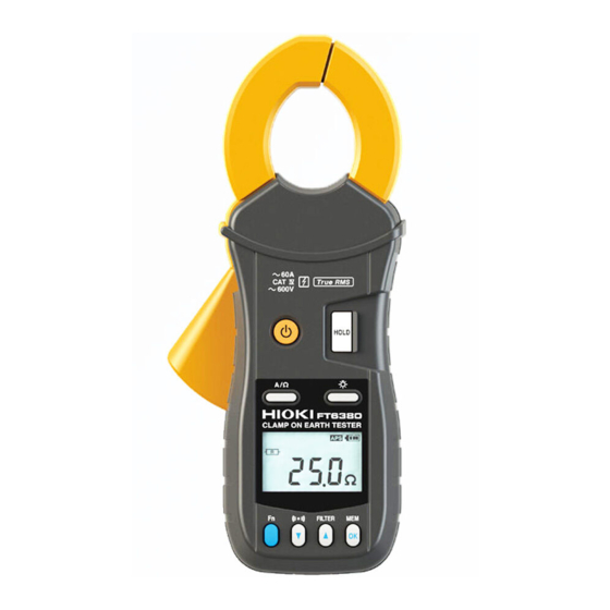
1.3 Names and Functions of Parts 1.3 Names and Functions of Parts Front FT6380 FT6381 Clamp sensor Barrier POWER key HOLD key (p.33) A/Ω key Backlight key (p.33) Display Indicator (p.17) Operation key (p.16) • Used to turn the instrument on and off. - Page 18 1.3 Names and Functions of Parts Back FT6381 FT6380 Serial No. Battery cover (p.21) Bottom Strap hole (p.20) GlobalTestSupply www. .com Find Quality Products Online at: sales@GlobalTestSupply.com...
-
Page 19: Operation Key
1.3 Names and Functions of Parts Operation key Description Switches to function mode, which is used to configure set- tings. Pressing this key again will return to resistance mea- surement mode or current measurement mode. • Enables the alarm function. (p.35) •... -
Page 20: Display Indicators
1.3 Names and Functions of Parts Display Indicators Lights up when data is being held. (p.33) Lights up in function mode. (p.50) Flashes in subfunction mode. (p.51) Lights up when the alarm function is on. (p.35) Lights up when the filter function is on. (p.34) ®... - Page 21 1.3 Names and Functions of Parts Lights up when the range display function is on. The measurement range is shown to the right. GlobalTestSupply www. .com Find Quality Products Online at: sales@GlobalTestSupply.com...
-
Page 22: Chapter 2 Measurement
2.1 Measurement process Measurement Chapter 2 2.1 Measurement process Measurement Preparations Pre-Operation Inspection (p.23) Using the included resistance check loop to inspect the instrument (p.24) Measurement Resistance Measurement (p.26) Current Measurement (p.29) End of measurement Remove the instrument from the measurement target. Turn off the instrument. -
Page 23: Preparing For Measurement
2.2 Preparing for Measurement 2.2 Preparing for Measurement After purchasing the instrument Complete the following steps before using the instrument to make measurements. Attaching the Strap Attach both ends of the Strap securely to the instrument. If insecurely attached, the instrument may fall and be damaged when carrying Thread the strap through the strap hole as shown in the follow- ing diagram:... -
Page 24: Installing (Or Replacing) The Battery
2.2 Preparing for Measurement Installing (or Replacing) the Battery Before using the instrument for the first time, install two AA-size alkaline batteries (LR6). Verify that there is sufficient battery power remaining before measurement. If there is insufficient bat- tery power remaining, replace the batteries. •... - Page 25 2.2 Preparing for Measurement Required Items: • Phillips screwdriver • LR6 alkaline battery (2) Normal procedure Verify that the instrument is off. Remove the fastening screws of the battery cover, using a Phillips screwdriver. Remove the battery cover. Insert two new batteries (LR06 alkaline batteries), taking care to orient them properly.
-
Page 26: Pre-Operation Inspection
Before using the instrument for the first time, verify that it oper- ates normally to ensure that no damage occurred during stor- age or shipping. If you find any damage, contact your dealer or Hioki representative. 1. Inspecting the instrument Do not use the instrument if it •... -
Page 27: Using The Included Resistance Check Loop To Inspect The Instrument
• If the instrument displays a value outside the allowable range, it needs to be repaired. Contact your dealer or Hioki representative. • The resistance check loop cannot be used to calibrate the instrument. To have the instrument calibrated, con- tact your dealer. -
Page 28: Measurement Procedure
2.4 Measurement Procedure Measurement Procedure • To avoid electric shock, do not touch the por- tion beyond the protective barrier during use. barrier • When the clamp sensor is opened, do not allow the metal part of the clamp to touch any exposed metal, or to short between two lines, and do not use over bare conductors. -
Page 29: Resistance Measurement
As illustrated below, the instrument is designed to measure grounding resistance at multiple grounding locations. (*For appli- cations involving the measurement of grounding resistance at a single grounding site, use Hioki’s 3151 EARTH HiTESTER.) If the grounding resistance of the measurement target is repre- sented by R... - Page 30 2.4 Measurement Procedure Example with actual measured values The following provides an example with actual measured values. The more grounding electrodes there are in the multiple- grounded installation, the higher the accuracy of the obtained values. Alternately, if even one grounding electrode has a small value (for example, 1 Ω), accurate values can be approached even if there are few grounding electrodes.
- Page 31 2.4 Measurement Procedure • Do not measure the same location with two or more Clamp On Earth Testers at the same time. The instru- ments will interfere with each other, preventing accu- rate measurement. • Verify that the mark is not lit up. When the current flowing through the grounding wire is high (approximately 2.5 A or greater with a commercial frequency of 50/60 Hz, approximately 100 mA or greater with a har-...
-
Page 32: Current Measurement
2.4 Measurement Procedure Current Measurement Select current measurement mode with the A/Ω key. Position the conductor in the center of the clamp sensor. The current RMS value will be shown on the display. GlobalTestSupply www. .com Find Quality Products Online at: sales@GlobalTestSupply.com... - Page 33 2.4 Measurement Procedure • The frequency of special waveforms such as at the secondary side of an inverter may not be indicated cor- rectly. • Depending on the magnitude and frequency of the input current, resonances may be heard from the clamp jaw.
- Page 34 2.4 Measurement Procedure Measuring zero-phase current When measuring zero-phase current, clamp all of the circuits at once. Single-phase, 2-lead circuits Load device three-phase 3-lead circuits Load device clamp all three leads of the circuit GlobalTestSupply www. .com Find Quality Products Online at: sales@GlobalTestSupply.com...
- Page 35 2.4 Measurement Procedure Do not input current that exceeds the maximum continu- ous input of the electric current range. • Measurement may not be accurate in the cases below. (1) When there is large current (of about 100 A) flow- ing through a nearby electric line (2) Note that a value of several tens of amperes may be displayed when opening or closing the clamp...
-
Page 36: Convenient Function
2.5 Convenient function 2.5 Convenient function Data hold function (Holding the measured value) This function holds the measured value and continues to display that value. Press the HOLD key. The instrument will beep twice and the ] mark will be displayed, and the measured value will be held. -
Page 37: Filter Function (Rejecting Noise)
2.5 Convenient function Filter function (Rejecting noise) This function allows you to reject unneeded frequency compo- nents such as high-frequency noise. Press the FILTER key. The [ ] mark will be displayed. To cancel the filter, press the FILTER key again. The [ ] mark will disappear. -
Page 38: Alarm Function (Judging Measured Values And Sounding An Alarm)
2.5 Convenient function Alarm function (Judging measured values and sounding an alarm) You can sound an alarm (A high tone signifies a high alarm, while a low tone signifies a low alarm.) using previously set thresholds by pressing the key. Thresholds and other settings must be configured in advance. - Page 39 2.5 Convenient function Set the alarm type (Hi/Lo). ▼ ▲ Using the keys, select the alarm type (Hi/Lo), and press the key. The next threshold setting will start flash- ing. Hi: The alarm will sound if the measured value is greater than the set threshold value. Lo: The alarm will sound if the measured value is less than the set threshold value.
- Page 40 2.5 Convenient function Set the threshold. After configuring the Hi/Lo setting, set the threshold. ▼ ▲ Using the keys, set the threshold and press the key. You can move more quickly through threshold values by ▼ ▲ pressing and holding the keys.
-
Page 41: Memory Function (Saving Measurement Data)
2.5 Convenient function Memory function (Saving measurement data) Press the key in either resistance measurement mode or current measurement mode. The instrument will beep three times and the displayed measured value will be stored along with the memory number (1 to 2,000) in the instrument’s internal memory. - Page 42 2.5 Convenient function Loading a value from the instrument’s internal memory Press the key to enter function mode. ▼ ▲ Using the keys, select the Read Memory screen and press the key. *For more information about function mode, see (p.50). ▼...
- Page 43 2.5 Convenient function Clearing stored data You can clear the last stored data point (1 value) or all stored data points. Press the key to enter function mode. ▼ ▲ Using the keys, select the Clear Memory screen and press the key.
- Page 44 2.5 Convenient function The [OK?] mark will flash on the LCD once you select the data to clear so that you can confirm your intentions. Press the key again to clear the data. • To cancel, press the key. • To return to resistance measurement or current mea- surement mode, press the key again or the A/Ω...
-
Page 45: Making Measurements With An Android™ Handset (Ft6381 Only)
2.5 Convenient function Making measurements with an Android™ handset (FT6381 only) ® By enabling the FT6381’s Bluetooth function, you can transfer measurement data to an Android™ handset to create measure- ment reports. For more information, refer to the help function of the FT6381 Communication Software, an app for Android™... -
Page 46: Enabling The Bluetooth® Function On The Ft6381
2.5 Convenient function ® Enabling the Bluetooth function on the FT6381 Press the key to enter function mode. For more information about function mode, see (p.50). ® ▼ ▲ Using the keys, select the Bluetooth Setting screen and press the key. -
Page 47: Pairing The Instrument With An Android™ Handset (First Use Only)
2.5 Convenient function Pairing the instrument with an Android™ handset (first use only) Select [Wireless and Networks] from the Android™ handset’s Settings button. ® After enabling the Bluetooth function, select [Scan for devices] from [Bluetooth settings] (exact words varies with the specific Android™ handset being used; variants include “Search for devices”... -
Page 48: Installing The Ft6381 Communication Software On The Android™ Handset
2.5 Convenient function *The screen contents vary with the specific Android™ handset ® being used. For more information about Bluetooth device pair- ing methods and related procedures, see your Android™ hand- set’s instruction manual. Installing the FT6381 Communication Software on the Android™... -
Page 49: Registering The Instrument You Wish To Connect With The Ft6381 Communication Software
Since such costs may be incurred during use of the application, it is rec- ommended to use a fixed-price plan. Hioki is not liable for any Internet connection costs. Registering the instrument you wish to connect with the FT6381 Communication Software Turn on the FT6381. - Page 50 "Precautions Concerning Use of Equip- ment That Emits Radio Waves" or the HIOKI products website may be subject to penalty as a violation of law. GlobalTestSupply www.
-
Page 51: Switching The Ft6381 To Connect With The Android™ Handset
2.5 Convenient function Using the FT6381 Communication Software (second and subsequent use) After turning on the FT6381, launch the FT6381 Communication Software on the Android™ handset. If you wish to use the map function, enable the GPS function. Once the instrument has been paired, it will connect automatically, and FT6381 measured values will be sent to the Android™... - Page 52 2.5 Convenient function About the FT6381 Communication Software The application provides the following functionality: Sending measurement data (from the LCD display) to the Android™ handset in real time Saving and viewing measurement data (including time stamp, GPS position data for the measurement location, and map data) Creating reports from measurement data •...
- Page 53 2.5 Convenient function Function mode In function mode, the following settings and operations are available: • Resistance alarm settings • Current alarm settings • Loading values from memory • Clearing data from the instrument’s ® memory • Bluetooth setting Press the key to enter func- tion mode.
-
Page 54: Advanced Settings And Functions
2.6 Advanced Settings and Functions 2.6 Advanced Settings and Functions Advanced settings can be configured in sub-function mode. In sub-function mode, the following settings and operations are available: • Measurement range display setting (p.52) • Auto-power-saving (APS) setting (p.53) • System reset (to revert to factory settings) (p.54) To enter sub-function mode, turn on the instrument by pressing POWER key while holding down the... -
Page 55: Enabling/Disabling The Measurement Range Display Function
2.6 Advanced Settings and Functions Enabling/disabling the measurement range display function Enter sub-function mode. Press the POWER key while holding down the key. ▼ ▲ Using the keys, select the Range Display Setting screen and press the key. ▼ ▲ Using the keys, switch the range display function on or off and press the... -
Page 56: Enabling/Disabling The Auto-Power-Saving (Aps) Function
2.6 Advanced Settings and Functions Enabling/disabling the auto-power-saving (APS) function The auto-power-saving (APS) function prevents unintentional battery consumption when you forget to turn off the instrument. The APS function activates automatically when the instrument is turned on. The instrument will automatically turn off once about 5 minutes pass without any operation (an alarm will sound for about 10 seconds first). -
Page 57: Reverting The Instrument To Factory Settings (System Reset)
2.6 Advanced Settings and Functions To disable APS temporarily Turn on the instrument by pressing the POWER while holding down the HOLD key to disable APS until the next time the instrument’s power is cycled. The next time the power is cycled, APS will be enabled (as long as the APS setting is enabled in sub-function mode). -
Page 58: Chapter 3 Specifications
3.1 Measurement Specifications Specifications Chapter 3 3.1 Measurement Specifications Common measurement specifications Guaranteed 1 year (Opening and Closing of the Sensor: Maximum 10000 accuracy period times) Accuracy guaran- 23°C±5°C (73°F±9°F) 80%RH or less (non-condensation) tee for tempera- ture and humidity Temperature -10 to 50°C Measurement accuracy x 0.1/°C (except 23°C±5°C) characteristics... - Page 59 3.1 Measurement Specifications Range Resolution Accuracy (Accuracy Range) 0.20 Ω (0.02 Ω to 0.20 Ω) 0.01 Ω ±1.5%rdg.±0.02 Ω 2.00 Ω (0.18 Ω to 2.00 Ω) 0.01 Ω ±1.5%rdg. ±0.02 Ω 20.00 Ω (1.80 Ω to 20.00 Ω) 0.01 Ω ±1.5%rdg.±0.05 Ω...
- Page 60 3.1 Measurement Specifications Current measurement specifications Guaranteed ac- Sine wave input curacy conditions Measurement Digital sampling method (true RMS measurement) method Crest factor 5.0 or less (for the 60 A range, 1.7 or less) Conductor Within ±0.5% rdg. (using the center of the sensor as the reference, position effects in all positions) Magnetic field...
- Page 61 3.1 Measurement Specifications Guaranteed Accuracy Range Resolu- accuracy (Accuracy Range) tion frequency range Filter off Filter on ±2.0%rdg. ±2.0%rdg. 45 ≤ f ≤ 66 Hz ±0.05 mA ±0.05 mA 20.00 mA (1.00 mA to 0.01mA 30 ≤ f < 45 Hz 20.00 mA) ±2.5%rdg.
-
Page 62: General Specifications
3.2 General Specifications 3.2 General Specifications Location for use Pollution Degree 2, altitude up to 2000 m (6562-ft.) Storage -20 to 60°C (-4.0°F to 140°F), 80%RH or less (non-condensation, temperature except for the battery) and humidity Operating Temperature : -10 to 50°C (14°F to 122°F) temperature Humidity : 80%RH or less (non-condensation) - Page 63 3.2 General Specifications Function mode mark lights up. Flashes in subfunction mode. display Filter display mark lights up. Auto-power-save mark lights up display Remaining Display of remaining battery power in 4 stages ( battery display Memory number mark lights up. display Range display mark lights up.
- Page 64 3.2 General Specifications Function specifications (underline: default value) Data hold function Backlight functionAutomatically turns off approx. 2 min. after last key operation. Filter function Resistance Moving average time: Max. 9 sec. measurement filter function Current Cutoff frequency: 180 Hz ±30 Hz (-3 dB) measurement filter function Alarm function...
- Page 65 3.2 General Specifications Sub-function mode Range display RNG: ON/OFF function Auto-power-save APS: ON/OFF function System reset SYS RST ® ® Bluetooth Bluetooth 2.1+ EDR (Class 2) function Communication range: 10 m (Line-of-sight) (FT6381) Displays measured values on the screen of an Android™ handset ®...
-
Page 66: Chapter 4 Maintenance And Service
4.1 Cleaning Maintenance and Service Chapter 4 4.1 Cleaning If foreign matter gets stuck between the tips of the clamp sen- sor, do not forcibly open or close the sensor, but rather use a soft brush or similar implement to carefully remove the foreign matter. -
Page 67: Troubleshooting
Include cush- ioning material so the instrument cannot move within the pack- age. Be sure to include details of the problem. Hioki cannot be responsible for damage that occurs during shipment. • Use the original packing materials when transporting the instrument, if possible. -
Page 68: Error Display
4.3 Error Display 4.3 Error Display If an error is shown on the LCD, the instrument needs to be repaired. Contact your dealer or Hioki representative. Error Display Meaning Remedial Action E001 Main CPU program error E002 Sub CPU program error Please contact your dealer or Hioki representative. - Page 69 保証書 HIOKI E.E. CORPORATION GlobalTestSupply www. .com Find Quality Products Online at: sales@GlobalTestSupply.com...
Need help?
Do you have a question about the FT6380 and is the answer not in the manual?
Questions and answers