Table of Contents
Advertisement
Quick Links
Advertisement
Table of Contents

Subscribe to Our Youtube Channel
Related Manuals for Hioki 9518-02


Summary of Contents for Hioki 9518-02
- Page 1 INSTRUCTION MANUAL 3157 AC GROUNDING HiTESTER 9518-02 GP-IB INTERFACE...
-
Page 3: Table Of Contents
Contents Introduction Chapter 1 Before Use 1.1 Check of External Appearance and Accessories 1.2 Shipping Precautions 1.3 Notes on Use 1.4 Installing the GP-IB Interface Chapter 2 Overview 2.1 Introduction to the GP-IB Interface 2.2 Features 2.3 Specifications Chapter 3 Names of Parts 3.1 Controls and Connections Chapter 4 Operation 4.1 Setting the GP-IB Device Address... - Page 4 5.3 Standard Commands 5.4 Commands Specific to the 3157 5.5 Response Format for Queries as Numerical Value 5.6 Initialization Items Chapter 6 Sample Programs Chapter 7 Device Compliance Statement Chapter 8 Troubleshooting...
-
Page 5: Introduction
──────────────────────────────────────────────────── Introduction Thank you for purchasing this HIOKI "9518-02 GP-IB INTERFACE." To get the maximum performance from the unit, please read this manual first, and keep this at hand. This Instruction Manual provides information and warnings essential for operating this equipment in a safe manner and for maintaining it in safe operating condition. - Page 6 ──────────────────────────────────────────────────── ──────────────────────────────────────────────────── Introduction...
-
Page 7: Chapter 1 Before Use
When the unit is delivered, check and make sure that it has not been damaged in transit. If the unit is damaged, or fails to operate according to the specifications, contact your dealer or HIOKI representative. (1) 9518-02 GP-IB INTERFACE (2) This instruction manual ────────────────────────────────────────────────────... -
Page 8: Shipping Precautions
──────────────────────────────────────────────────── 1.2 Shipping Precautions If reshipping the unit, preferably use the original packing. If this is not available, use the following procedure. (1) Wrap the unit in plastic sheeting. (2) After wrapping cushioning material around the unit, pack it into a cardboard box, and then seal up the box with adhesive tape. -
Page 9: Notes On Use
If you do not do so, the address change will not be registered by the bus, and problems will occur. (2) Always be sure to secure the GP-IB cable to the 9518-02 unit by tightening up the fixing screws provided. -
Page 10: Installing The Gp-Ib Interface
The space for fitting the 9518-02 GP-IB INTERFACE in the rear panel of the 3157 is covered with a blank panel. Follow these three steps to install the 9518-02 interface: (1) Remove the fixing screws, and take off the blank panel. -
Page 11: Chapter 2 Overview
Further, the 9518-02 is designed with reference to the following standard: Reference standard : IEEE 488.2-1987 On the 9518-02, if the output queue becomes full, it is cleared and a query NOTE error is generated. This differs from the IEEE 488.2 specification, which... -
Page 12: Specifications
──────────────────────────────────────────────────── 2.3 Specifications Interface functions All source handshake functions All acceptor handshake functions Basic talk functions Serial poll function No talk-only mode The talker cancellation function with MLA (My Listen Address) Basic listener functions No listen-only mode The listener cancellation function with MTA (My Talk Address) is provided. -
Page 13: Chapter 3 Names Of Parts
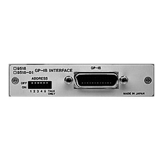
──────────────────────────────────────────────────── Chapter 3 Names of Parts 3.1 Controls and Connections (1) 3157 front panel Display of GP-IB status Each lamp displays the state of control by the GP-IB. RMT: Remote Remote state releasing keys Press the key while holding down the key to release the remote 0ADJ SHIFT... - Page 14 ──────────────────────────────────────────────────── (2) 9518-02 GP-IB interface outer panel Address switches These are used to set the device address of the 3157 unit on the GP-IB bus. For how to set these switches, refer to Section 4.1, "Setting the GP-IB Device Address."...
-
Page 15: Chapter 4 Operation
──────────────────────────────────────────────────── Chapter 4 Operation 4.1 Setting the GP-IB Device Address ・The address of the 3157 unit (called the device) on the GP-IB bus can be set to any number from 0 to 30. ・Use the Address switches on the GP-IB panel to set the device address. ・On dispatch from the factory, this address is initially set to 1. - Page 16 ──────────────────────────────────────────────────── 0: OFF, 1: ON Switch settings Switch settings Switch settings Address Address Address 12345 12345 12345 00000 11010 01101 10000 00110 11101 01000 10110 00011 11000 01110 10011 00100 11110 01011 10100 00001 11011 01100 10001 00111 11100 01001 10111 00010 11001...
-
Page 17: Communication Methods By The Gp-Ib
──────────────────────────────────────────────────── 4.2 Communication Methods by the GP-IB In order to control the 3157 by the GP-IB, there are several kinds of messages. Of these, program messages are those received by the 3157 from the computer, while response messages are those sent from the 3157 to the computer. Command messages Program messages Query messages... -
Page 18: Message Format
──────────────────────────────────────────────────── 4.3 Message Format The commands for the 3157 are as far as possible mnemonic. Furthermore, all commands have a long form, and an abbreviated short form. 4.3.1 Program Message The program message is made up from header and data portions. Example Command message to set test time to ON :TIMER_ON... -
Page 19: Headers
──────────────────────────────────────────────────── 4.4 Headers (1) Program message headers There are three types of header: simple commands, compound commands, and standard common commands. ・Simple command header A header consisting of a single word beginning with a letter. Examples :HEADer etc. ・Compound commands header A header consisting of a sequence of words separated by colons. -
Page 20: Data Formats
──────────────────────────────────────────────────── 4.5 Data Formats The 3157 uses character string data and decimal numeric data, and the type used varies according to the command in question. (1) Character data Character string data must always begin with an alphabetic character, and the characters following can be either alphabetic characters or numerals. Although in character data either upper case letters or lower case letters are accepted, response messages output by the 3157 are always in upper case letters. -
Page 21: Message Terminators
──────────────────────────────────────────────────── 4.6 Message Terminators The 3157 recognizes either a linefeed character (LF) or the EOI signal, or both, as message terminators. To terminate a response message, the 3157 always provides the appropriate EOI signal, and also sends a terminating character sequence. By the use of the ":TRANsmit:TERMinator"... -
Page 22: Abbreviation Of Compound Commands
──────────────────────────────────────────────────── 4.8 Abbreviation of Compound Commands When several compound commands have a common head portion (for example, :CONFigure:CURRent and :CONFigure:RUPPer, etc.), then, when and only when writing them directly following on from one another, this common portion (:CONFigure in this example) can be omitted from each command except for the first one. -
Page 23: Output Queue
──────────────────────────────────────────────────── 4.9 Output Queue Response messages accumulate in the output queue and are read out as data and cleared by the controller. The output queue is also cleared in the following circumstances: ・When a device clear is issued. ・When the power is turned off and turned on again. The 3157 has an output queue of 300 bytes capacity. -
Page 24: Status Model
──────────────────────────────────────────────────── 4.11 Status Model In its implementation of the serial polling function using service requests, the 3157 employs the status model specified by IEEE 488.2. The term "event" refers to any phenomenon which generates a service request. Status byte register (STB) Represents standard event register Generation of service request (SRQ) Data is present in the output queue... -
Page 25: Status Byte Register
──────────────────────────────────────────────────── 4.12 Status Byte Register (1) Status byte register (STB) The status byte register is an 8-bit register whose contents are output from the 3157 to the controller, when serial polling is being performed. If any bit in the status byte register has changed from 0 to 1 (provided that it is a bit which has been set in the service request enable register as a bit which can be used), then the MSS bit is set to 1. -
Page 26: Event Registers
──────────────────────────────────────────────────── 4.13 Event Registers (1) Standard event status register (SESR) The standard event status register is an 8-bit register. If any bit in the standard event status register is set to 1 (after masking by the standard event status enable register), bit 5 (ESB) of the status byte register is set to 1. tatus byte register (STB) bit 6 Standard event status register (SESR) - Page 27 ──────────────────────────────────────────────────── (2) Standard event status enable register (SESER) Setting any bit of the standard event status enable register to 1 enables the corresponding bit of the standard event status register to be accessed. Standard event status register (SESR) bit assignments Power on flag.
- Page 28 ──────────────────────────────────────────────────── (3) Event status register specific to the 3157 (ESR0) An 8-bit event status register is provided for managing events on the 3157. If any bit in this event status register is set to 1 (after masking by the corresponding event status enable register), the following happens: ・For event status register 0, bit 0 of the status byte register (ESB0) is set to 1.
- Page 29 ──────────────────────────────────────────────────── (5) Summary of commands for writing and reading each of the registers Register Read Write Status byte register * STB? ── Service request enable register * SRE? * SRE ── Standard event status register * ESR? Standard event status enable register * ESE? * ESE ──...
-
Page 30: Gp-Ib Commands
──────────────────────────────────────────────────── 4.14 GP-IB Commands The following commands are used for performing interface functions: Command Function Go To Local The remote state is canceled,, and the system goes into the local state. Local Lock Out All keys, including the LOCAL key, become inoperable. Device Clear Clears the input buffer and the output queue. -
Page 31: Chapter 5 Command Reference
──────────────────────────────────────────────────── Chapter 5 Command Reference 5.1 Command Summary Standard commands Command Explanation page Clears event register. Sets standard event status enable register (SESER). Queries standard event status enable register (SESER). ESE? ESR? Queries standard event status register (SESR). Queries device ID. IDN? Issues service request (SRQ) after execution completion. - Page 32 ──────────────────────────────────────────────────── Commands specific to the 3157 Command Explanation page :ADJust Enables and disables the zero adjustment function. Queries the zero adjustment function enablement. :ADJust? :CONFigure? Queries the test settings. Sets the output current value. :CONFigure:CURRent :CONFigure:CURRent? Queries the output current value. Sets the number of test data.
- Page 33 ──────────────────────────────────────────────────── Command Explanation page :STOP Performs forcible ending of a test and releases the hold state. :SYSTem:OPTion:BUZZer Sets the buzzer. :SYSTem:OPTion:BUZZer? Queries the buzzer. Sets the current changeability in the TEST state. :SYSTem:OPTion:CCHange :SYSTem:OPTion:CCHange? Queries the current changeability in the TEST state. Sets the maximum number of test data in the test data count :SYSTem:OPTion:CDATa function.
-
Page 34: Format Of Command Explanations
──────────────────────────────────────────────────── 5.2 Format of Command Explanations Specifies the syntax for the command (a space is represented by "_" in this Syntax syntax). <data> For a command that has parameters, specifies their format. Specifies the function of the command. Function Note Specifies precautions to be taken when using the command. -
Page 35: Standard Commands
──────────────────────────────────────────────────── 5.3 Standard Commands * CLS ■ Clears the status byte register and the event registers. Syntax * CLS Function ・ Clears all the event registers (SESR, ESR0) associated with the bits of the status byte register. Accordingly, also clears the status byte register. ・... - Page 36 Manufacturer’s name Second field Model name Third field Serial number (Not used - always zero) Fourth field Software version Example HIOKI,3157,0,V01.01 Response Error If the response message is longer than 300 bytes, a query error is generated. ──────────────────────────────────────────────────── 5.3 Standard Commands...
- Page 37 ──────────────────────────────────────────────────── * OPC ■ After all action has been completed during execution, performs an SRQ request. Syntax * OPC Function Sets bit 0 (the OPC bit) of the standard event status register (SESR) to 1 at the instant the previous commands which is on the same line with *OPC have been completed.
- Page 38 ──────────────────────────────────────────────────── * SRE ■ Sets the service request enable register. Syntax * SRE _<data> <data> Numerical data in NR1 format between 0 and 255 Function ・ Sets a pattern which is used to mask the status byte register (STB) to the service request enable register (SRSR).
- Page 39 Note The *WAI command is accepted by the 9518-02 interface because it is a standard command as specified by IEEE-488.2 1987. However, since all of the commands specific to the 3157 are in any case sequential commands, using this *WAI command never has any effect.
-
Page 40: Commands Specific To The 3157
──────────────────────────────────────────────────── 5.4 Commands Specific to the 3157 :ADJust ■ Enables and disables the zero adjustment function. Syntax :ADJust _<data> <data> ON/OFF (character data) Function ・Turns the zero adjustment function on and off. Example Transmission :ADJust ON The zero adjustment function is turned on. Error If <data>... - Page 41 ──────────────────────────────────────────────────── :CONFigure? ■ Queries the test settings. Syntax :CONFigure? Function Returns as data the test settings as <output current value>, <maximum test value>, <minimum test value>, <test time> in order. If the unit of the maximum and minimum test values is set to "OHM" (resistance), the maximum and minimum test values are expressed as resistance values.
- Page 42 ──────────────────────────────────────────────────── :CONFigure:CURRent? ■ Queries the output current value. Syntax :CONFigure:CURRent? Function Returns the output current value setting as a numerical value in NR2 format. <data> Numerical data in NR2 format between 3.0 and 31.0 Note If the output current value is reset in the TEST state (test in progress), the reset value is returned.
- Page 43 ──────────────────────────────────────────────────── :CONFigure:RLOWer ■ Sets the minimum test value (resistance). Syntax :CONFigure:RLOWer _<data> <data> Numerical data in NR2 format between 0.000 and 2.000 Function Sets the minimum test value (resistance). The numerical value can be in NRf format, but rounding is performed for figures beyond the last valid decimal place.
- Page 44 ──────────────────────────────────────────────────── :CONFigure:RUPPer ■ Sets the maximum test value (resistance). Syntax :CONFigure:RUPPer _<data> <data> Numerical data in NR2 format between 0.000 and 2.000 Function Sets the maximum test value (resistance). The numerical value can be in NRf format, but rounding is performed for figures beyond the last valid decimal place.
- Page 45 ──────────────────────────────────────────────────── :CONFigure:TIMer ■ Sets the test time. Syntax :CONFigure:TIMer _<data> <data> Numerical data in NR1 or NR2 format between 0.5 and 999 Function Sets the test time. The numerical value can be in NRf format, but rounding is performed for figures beyond the last valid decimal place.
- Page 46 ──────────────────────────────────────────────────── :CONFigure:VLOWer ■ Sets the minimum test value (voltage). Syntax :CONFigure:VLOWer _<data> <data> Numerical data in NR2 format between 0.00 and 6.00 Function Sets the minimum test value (voltage). The numerical value can be in NRf format, but rounding is performed for figures beyond the last valid decimal place.
- Page 47 ──────────────────────────────────────────────────── :CONFigure:VUPPer ■ Sets the maximum test value (voltage). Syntax :CONFigure:VUPPer _<data> <data> Numerical data in NR2 format between 0.00 and 6.00 Function Sets the maximum test value (voltage). The numerical value can be in NRf format, but rounding is performed for figures beyond the last valid decimal place.
- Page 48 ──────────────────────────────────────────────────── :ESE0 ■ Sets event status enable register 0. Syntax :ESE0 Function Sets event status enable register 0 (ESER0) to the bitmask for controlling access to events in event status register 0 (ESR0). The numerical value can be in NRf format, but any digits after the decimal point will be rounded.
- Page 49 ──────────────────────────────────────────────────── :ESR0? ■ Queries event status register 0. Syntax ESR0? Function Returns the value of event status register 0 (ESR0) as a numerical value in NR1 format between 0 and 255, and then clears event status register 0. No header is prefixed to the response message. bit 7 bit 6 bit 5...
- Page 50 ──────────────────────────────────────────────────── :KEY ■ Sets key entry. Syntax :KEY _<data 1>, <data 2> <data 1> Numerical data in NR1 format between 0 and 1 <data 2> Numerical data in NR1 format of 1, 2, 4, 8, 16, 32, 64 to 66, 68, 72, 80, 96, 128 Function Sets the key registers 0 and 1 (KEY0 and KEY1).
- Page 51 ──────────────────────────────────────────────────── :LOWer? ■ Queries the minimum test value enablement. Syntax :LOWer? Function Returns the current enablement state of the minimum test value as character data. <data> ON/OFF (character data) Example Response If headers are on :LOWER ON If headers are off Error If the response message is longer than 300 bytes, a query error is generated.
- Page 52 ──────────────────────────────────────────────────── :MEASure:RESistance? ■ Queries the measured resistance value. Syntax :MEASure:RESistance? Function Returns the measured resistance value as a numerical value in NR2 format. <data> O.F. (character data) Numerical data in NR2 format between 0.0 and 35.0 Note The measured current value is returned in the TEST state (test in progress), and the result of the previous test is returned in the other states.
- Page 53 ──────────────────────────────────────────────────── :MEASure:VOLTage? ■ Queries the measured voltage value. Syntax :MEASure:VOLTage? Function Returns the measured voltage value as a numerical value in NR2 format. <data> Numerical data in NR2 format between 0.00 and 6.00 Note The measured current value is returned in the TEST state (test in progress), and the result of the previous test is returned in the other states.
- Page 54 ──────────────────────────────────────────────────── :MEASure:RESult:RESistance? ■ Queries the measured value and result (resistance). Syntax :MEASure:RESult:RESistance? Function Returns as data the measured value and result as <measured current value>, <measured resistance value>, <test time elapsed>, <screening result> in order. If the unit of the maximum and minimum test values is set to "VOLT" (voltage), the measured resistance value and screening result are OFF.
- Page 55 ──────────────────────────────────────────────────── :MEMory:FILE? ■ Queries the contents of Setting memory. Syntax :MEMory:FILE? _<data 1> <data 1> Numerical data in NR1 format between 1 and 20 Function Returns as data (<data2>) the contents of Setting memory numbered <data 1> as <output current value>, <maximum test value>, <minimum test value>, <test time>...
- Page 56 ──────────────────────────────────────────────────── :MEMory:SAVE ■ Saves in Setting memory. Syntax :MEMory:SAVE _<data> <data> Numerical data in NR1 format between 1 and 20 Function Saves the current settings in Setting memory numbered <data>. The numerical value can be in NRf format, but any digits after the decimal point will be rounded.
- Page 57 ──────────────────────────────────────────────────── :STOP ■ Performs forcible ending of a test and releases the hold state. Syntax :STOP Function In the TEST state (test in progress), performs forcible ending of a test. When retaining the test result, returns to the READY state. In the save screen, returns to the READY state without saving.
- Page 58 ──────────────────────────────────────────────────── :SYSTem:OPTion:CCHange ■ Sets the current changeability in the TEST state. Syntax :SYSTem:OPTion:CCHange _<data> <data> Numerical data in NR1 format between 0 and 1 Function Sets the current changeability in the TEST state. 0: Not changeable 1: Changeable The numerical value can be in NRf format, but any digits after the decimal point will be rounded.
- Page 59 ──────────────────────────────────────────────────── :SYSTem:OPTion:CDATa ■ Sets the maximum number of test data in the test data count function. Syntax :SYSTem:OPTion:CDATa _<data> <data> Numerical data in NR1 format between 1 and 99 Function Sets the maximum number of test data in the test data count function. The numerical value can be in NRf format, but any digits after the decimal point will be rounded.
- Page 60 ──────────────────────────────────────────────────── :SYSTem:OPTion:COUNt ■ Sets the test data count function. Syntax :SYSTem:OPTion:COUNt _<data> <data> Numerical data in NR1 format between 0 and 1 Function Sets the test data count function. 0: Not set 1: Set The numerical value can be in NRf format, but any digits after the decimal point will be rounded.
- Page 61 ──────────────────────────────────────────────────── :SYSTem:OPTion:ENDLess ■ Sets the endless timer function. Syntax :SYSTem:OPTion:ENDLess _<data> <data> Numerical data in NR1 format between 0 and 1 Function Sets the endless timer function. 0: Not set 1: Set The numerical value can be in NRf format, but any digits after the decimal point will be rounded.
- Page 62 ──────────────────────────────────────────────────── :SYSTem:OPTion:FREQuency ■ Sets the output current frequency. Syntax :SYSTem:OPTion:FREQuency _<data> <data> Numerical data in NR1 format between 0 and 1 Function Sets the output current frequency. 0: 50 Hz 1: 60 Hz The numerical value can be in NRf format, but any digits after the decimal point will be rounded.
- Page 63 ──────────────────────────────────────────────────── :SYSTem:OPTion:HOLD ■ Sets the hold function. Syntax :SYSTem:OPTion:HOLD _<data> <data> Numerical data in NR1 format between 0 and 1 Function Sets the hold function. 0: Not held 1: Held The numerical value can be in NRf format, but any digits after the decimal point will be rounded.
- Page 64 ──────────────────────────────────────────────────── :SYSTem:OPTion:LOWer ■ Sets the minimum test value. Syntax :SYSTem:OPTion:LOWer _<data> <data> Numerical data in NR1 format between 0 and 1 Function Sets the minimum test value. 0: Not set 1: Set The numerical value can be in NRf format, but any digits after the decimal point will be rounded.
- Page 65 ──────────────────────────────────────────────────── :SYSTem:OPTion:MOMentary ■ Sets the momentary OUT function. Syntax :SYSTem:OPTion:MOMentary _<data> <data> Numerical data in NR1 format between 0 and 1 Function Sets the momentary OUT function. 0: Not set 1: Set The numerical value can be in NRf format, but any digits after the decimal point will be rounded.
- Page 66 ──────────────────────────────────────────────────── :SYSTem:OPTion:PFHold ■ Sets the PASS/FAIL hold function. Syntax :SYSTem:OPTion:PFHold _<data> <data> Numerical data in NR1 format between 0 and 3 Function Sets the PASS/FAIL hold function. 0: PASS not held, FAIL held 1: PASS held, FAIL held 2: PASS not held, FAIL not held 3: PASS held, FAIL not held The numerical value can be in NRf format, but any digits after the decimal point will be rounded.
- Page 67 ──────────────────────────────────────────────────── :SYSTem:OPTion:PRINter ■ Sets the printer output function. Syntax :SYSTem:OPTion:PRINter _<data> <data> Numerical data in NR1 format between 0 and 2 Function Sets the printer output function. 0: Not used 1: Automatically print for PASS/FAIL screening. 2: Print selectively when the PASS/FAIL state is held. The numerical value can be in NRf format, but any digits after the decimal point will be rounded.
- Page 68 ──────────────────────────────────────────────────── :SYSTem:OPTion:TMODe ■ Sets the test mode. Syntax :SYSTem:OPTion:TMODe _<data> <data> Numerical data in NR1 format between 0 and 2 Function Sets the test mode. 0: Soft start mode 1: Normal mode 2: Continuous test mode The numerical value can be in NRf format, but any digits after the decimal point will be rounded.
- Page 69 ──────────────────────────────────────────────────── :TIMer ■ Enables and disables the test time. Syntax :TIMer _<data> <data> ON/OFF (character data) Function Enables and disables the test time. Note When the endless timer function is set, the ON/OFF setting for the test time is not reflected in the test. Example Transmission :TIMer ON...
- Page 70 ──────────────────────────────────────────────────── :TRANsmit:TERMinator? ■ Queries the data terminator for response messages. Syntax :TRANsmit:TERMinator? Function Returns the data terminator for response messages as a numerical value (0 or 1) in NR1 format. If <data> = 0, the terminator is LF and EOI signal. If <data>...
- Page 71 ──────────────────────────────────────────────────── :UPPer ■ Enables and disables the maximum test value. Syntax :UPPer _<data> <data> ON/OFF (character data) Function Enables and disables the maximum test value. Example Transmission :UPPer ON The maximum test value is set to ON. Error If <data> is other than character data and numerical value described above, a command error occurs.
-
Page 72: Response Format For Queries As Numerical Value
──────────────────────────────────────────────────── 5.5 Response Format for Queries as Numerical Value The response formats are as follows. (1) Output current value and measured current value □.□ □□.□ Two or three digits (in NR2 format) (2) Maximum test value (voltage), minimum test value (voltage) and measured voltage value □.□□... -
Page 73: Initialization Items
──────────────────────────────────────────────────── 5.6 Initialization Items The following table shows which items are initialized and which not, under various conditions. Initialization method Powering * RST Device * CLS command clear command Item GP-IB device address ─ ─ ─ ─ Device specific functions ─... - Page 74 ──────────────────────────────────────────────────── ──────────────────────────────────────────────────── 5.6 Initialization Items...
-
Page 75: Chapter 6 Sample Programs
──────────────────────────────────────────────────── Chapter 6 Sample Programs The following sample programs are all written for the Hewlett-Packard HP9000 Series 300, using BASIC 4.0. All commands in the sample programs are used in the short form, and the GP-IB device address of the 3157 is taken as 1. (1) Basic settings and testing This program sets the 3157 to the following test values: ・... - Page 76 ──────────────────────────────────────────────────── 380 OUTPUT 701;":MEAS:RES:RES?" 390 ENTER 701;C$ 400 PRINT C$ 410 IF BINAND(D,2)=2 THEN OUTPUT 701;":STOP" 430 END IF 440 GOTO Exit1 450 Interrupt: ! 460 P=SPOLL(701) 470 OUTPUT 701;":ESR0?" 480 ENTER 701;D 490 IF BINAND(D,8)=8 THEN F=1 500 DISABLE INTR 7 510 OUTPUT 701;"*CLS"...
- Page 77 ──────────────────────────────────────────────────── Program List 100 DIM A$[10],B$[10],C$[10],D$[10],E$[10] 110 Statecheck1: ! 120 OUTPUT 701;":STAT?" 130 ENTER 701;A$ 140 IF A$="READY" THEN GOTO Setting1 150 OUTPUT 701;":STOP" 160 GOTO Statecheck1 170 Setting1: ! 180 OUTPUT 701;":CONF:CURR 25.0" 190 OUTPUT 701;":UNIT OHM" 200 OUTPUT 701;":UPP ON" 210 OUTPUT 701;":CONF:RUPP 0.100"...
- Page 78 ──────────────────────────────────────────────────── Program comments Line Comment 110-160 Confirm that the 3157 is in the READY state. Perform test settings in Setting memory 1. 170-240 250-280 Make sure that saving has been completed. 290-360 Perform test settings in Setting memory 2. Make sure that saving has been completed. 370-400 410-480 Perform test settings in Setting memory 3.
- Page 79 ──────────────────────────────────────────────────── (4) Testing at five positions and outputting of a text data file After test settings, five tests are made, and their results are outputted in a text data file. Program List 100 DIM R$[10],T$[40],Te$[10],K$[10],Res$[40] 110 N=0 120 CREATE ASCII "FILE1",100 130 ASSIGN @Path TO "FILE1"...
- Page 80 ──────────────────────────────────────────────────── Sample display 25.1,0.090,5.0,PASS 25.2,0.098,5.0,PASS 24.6,0.101,0.1,UFAIL 24.7,0.102,0.1,UFAIL 5,24.7,0.101,0.1,UFAIL Sample output 1,25.1,0.090,5.0,PASS 2,25.2,0.098,5.0,PASS 3,24.6,0.101,0.1,UFAIL 4,24.7,0.102,0.1,UFAIL 5,24.7,0.101,0.1,UFAIL ────────────────────────────────────────────────────...
-
Page 81: Chapter 7 Device Compliance Statement
──────────────────────────────────────────────────── Chapter 7 Device Compliance Statement The following information relates to compliance with the IEEE 488.2 standard. (1) IEEE 488.1 interface functions These are detailed in Section 2.3, "Specifications." (2) Operation with a device address other than 0 through 30 The bus is disabled. - Page 82 ──────────────────────────────────────────────────── (6) Summary of functional elements for use when constructing device specific commands, and whether compound commands or program headers can be used: ・ Program message, program message terminator, program message unit, program message unit separator, command message unit, query message unit, command program header, query program header, program data, character program data, and decimal program data.
- Page 83 ──────────────────────────────────────────────────── (20) Scope of the self-testing executed as a result of the "*TST?" query This is detailed in Section 5.3, "Standard Commands." (21) Additional organization of the status data used in a device status report This is detailed in Section 4.13, "Event Registers." (22) Whether commands are overlap or sequential type All the commands are sequential commands.
- Page 84 ──────────────────────────────────────────────────── ────────────────────────────────────────────────────...
-
Page 85: Chapter 8 Troubleshooting
──────────────────────────────────────────────────── Chapter 8 Troubleshooting If the GP-IB appears to be malfunctioning, refer to the information below before calling for servicing. Symptom Cause / Treatment Are the cables properly connected? Is the device address for the 3157 set correctly? The GP-IB has stopped working completely. - Page 86 3157. instant that the controller reads it in. Service If the unit is not functioning properly, check the "Troubleshooting" list. If a problem is found, contact your dealer or HIOKI representative. ────────────────────────────────────────────────────...
Need help?
Do you have a question about the 9518-02 and is the answer not in the manual?
Questions and answers