
Related Manuals for Hioki 8205-10


Summary of Contents for Hioki 8205-10
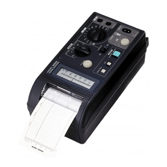
- Page 1 Instruction Manual 8205-10 MICRO HiCORDER July 2013 Revised edition 10 8205B981-10 13-07H...
-
Page 3: Table Of Contents
Contents Introduction Inspection Safety Notes Notes on Use Chapter Summary viii Chapter 1 Product Overview 1.1 Product Overview 1.2 Features 1.3 Front Panel 1.4 LCD (Display) 1.5 Printout Information Chapter 2 Measurement Procedures 2.1 Preparations 2.2 DC Voltage Measurement 2.3 AC Voltage Measurement 2.4 AC Current Measurement 1 2.5 AC Current Measurement 2 2.5.1 When Measuring High Voltage and High... - Page 4 Chapter 4 Specifications 4.1 General Specifications 4.2 Voltage Measurement Input Specifications 4.3 Current Measurement Input Specifications 4.4 Display Specifications 4.5 Recorded Information 4.6 Recording Time Chapter 5 Maintenance and Service 5.1 Storage Precautions 5.2 Cleaning 5.3 Cleaning the Printer Head 5.4 Service...
- Page 5 _____________________________________________________________________ Introduction Thank you for purchasing the Hioki 8205-10 MICRO HiCORDER. To obtain maximum performance from the instrument, please read this manual first, and keep it handy for future reference. Inspection When you receive the instrument, inspect it carefully to ensure that no damage occurred during shipping.
-
Page 6: Safety Notes
_____________________________________________________________________ Safety Notes This instrument is designed to conform to IEC 61010 Safety Standards, and has been thoroughly tested for DANGER safety prior to shipment. However, mishandling during use could result in injury or death, as well as damage to the instrument. Be certain that you understand the instructions and precautions in the manual before use. - Page 7 _____________________________________________________________________ The following symbols in this manual indicate the relative importance of cautions and warnings. Indicates that incorrect operation presents an extreme hazard that could result in serious injury or death to DANGER the user. Indicates that incorrect operation presents a significant hazard that could result in serious injury or WARNING death to the user.
- Page 8 _____________________________________________________________________ Measurement categories This instrument complies with CAT III safety requirements. To ensure safe operation of measurement instruments, IEC 61010 establishes safety standards for various electrical environments, categorized as CAT II to CAT IV, and called measurement categories. These are defined as follows. CATII Primary electrical circuits in equipment connected to an AC electrical outlet by a power cord (portable tools,...
-
Page 9: Notes On Use
_____________________________________________________________________ Notes on Use Follow these precautions to ensure safe operation and to obtain the full benefits of the various functions. The maximum input voltage is 500 V DC/AC. Attempting to measure voltage in excess of the maximum input DANGER voltage could destroy the instrument and result in personal injure or death. - Page 10 _____________________________________________________________________ This instrument is designed for indoor use, and operates CAUTION reliably from 5 to 40℃. Do not store or use the instrument where it could be exposed to direct sunlight, high temperature or humidity, or condensation. Under such conditions, the instrument may be damaged and insulation may deteriorate so that it no longer meets specifications.
- Page 11 WARNING that no bare conductors are improperly exposed. Using the instrument in such conditions could cause an electric shock, so contact your dealer or Hioki representative for repair. ______________________________________________________________ Notes on Use...
-
Page 12: Chapter Summary
viii _____________________________________________________________________ Chapter Summary This manual consists of the following chapters. "Introduction", "Safety Notes", "Notes on Use" describe precautions on use, overview, and features of this unit. Be sure to read them all. Next, check Chapter 1 to 5 and the unit to confirm your understanding of the function. -
Page 13: Chapter 1 Product Overview
_____________________________________________________________________ Chapter 1 Product Overview ______________________________________________________________ Product Overview... -
Page 14: Product Overview
_____________________________________________________________________ 1.1 Product Overview The multi-functional recording Model 8205-10 MICRO HiCORDER is almost as easy to use as a simple DMM. A broad range of applications, from small-signal electronic circuitry to commercial power circuits, are supported by wide AC and DC voltage measurement ranges covering 0.1... -
Page 15: Features
_____________________________________________________________________ 1.2 Features (1) Easy operation The large single-function controls allow operation without requiring repeated reference to the manual. (2) Graduated analog-style amplitude display The high-resolution graduated display and data display matching the selected range allow input signal levels to be viewed like an analog meter. -
Page 16: Front Panel
_____________________________________________________________________ 1.3 Front Panel Printer Cover LCD (display) PAPER FEED Button POSITION Control ADJ Button SPEED Selector Indicator CHART Button FUNCTION Switch RANGE Selector A (CLAMP) Selector Clamp Terminals Test Voltage Input Terminals POWER SOURCE Switch POWER Switch AC Connector GND Terminal DC Terminals (DC Power Source) ______________________________________________________________... - Page 17 _____________________________________________________________________ LCD (display) Displays the signal level and device status, including selected mode and range, numeric scale values, and indicators. States such as print head up, out of paper and low supply voltage are also displayed. PAPER FEED Button Manually advances the recording paper Pressing this button momentarily advances the paper about 30 mm.
-
Page 18: Lcd (Display)
_____________________________________________________________________ 1.4 LCD (Display) Positive Over-range Indicator Print Head Up Indicator Pointer Scale Paper End Indicator Numeric Display Under-range Indicator Low (DC) Supply Voltage Indicator Negative Over-range Indicator This arrow lights when the input signal exceeds the upper limit of the selected range (the highest level segment lights at the same time). -
Page 19: Printout Information
_____________________________________________________________________ 1.5 Printout Information Example of DC-5 V range case Setup Range Data 1 Printing Waveform Interval Printing Setup Range Data 2 Model Recording Waveform Trademark Scale Elapsed Time Display Setup Range Data 1 The print setup signal type, numeric value of the range and display units are printed once when the CHART button is pushed (ON). - Page 20 _____________________________________________________________________ NOTE When the printing speed is set to 20 cm/min (maximum), the recording waveform prints lightly. ______________________________________________________________ Product Overview...
-
Page 21: Chapter 2 Measurement Procedures
_____________________________________________________________________ Chapter 2 Measurement Procedures 2.1 Preparations To avoid electric accidents and to maintain the safety specifications of this instrument, connect the power WARNING cord provided only to a 3-contact (two-conductor + ground) outlet. To avoid electrical accidents, turn the power switch off and unplug the power cords from the outlet after use. - Page 22 _____________________________________________________________________ AC Operation Set the switch to POWER SOURCE (AC) position. Connect the supplied power cord to the socket on the recorder. Plug in the power cord. Insert the plug directly into the outlet. NOTE Although the product can operate from 100 to 240 V AC, the power cord should be selected to conform to the requirements of the mains voltage used.
- Page 23 _____________________________________________________________________ DC Operation Set the switch to POWER SOURCE (DC) position. Connect the GND terminal to earth ground. Connect a source of 9.5 to 14-V DC to the terminals. Negative Positive From 9.5 to 14-V DC power source NOTE A proper ground connection is important for safety and to ensure stable operation.
- Page 24 _____________________________________________________________________ NOTE We recommend the following wiring for power connections. PVC-insulated ring-type crimp-on terminals (3.2-mm ID, less than 6-mm OD) Vinyl-insulated wire, at least 1.25 mm (#14 AWG) (3) Powering on Slide the switch to the on POWER position ( The LCD should light.
-
Page 25: Dc Voltage Measurement
_____________________________________________________________________ 2.2 DC Voltage Measurement To avoid electric shock, short circuits and damage to the instrument, observe the following precautions: DANGER The maximum input voltage is 500 V DC/500 VrmsAC. Attempting to measure voltage in excess of the maximum input voltage could destroy the instrument and result in personal injure or death. - Page 26 _____________________________________________________________________ Example 1 Measuring the continuous operation of a device. Battery used for test: 6F22 (9V) Estimated recording period: 90 hours Measure continuously until the battery replacement warning is displayed. The supplied connection cords connect to the Test voltage input terminals.
- Page 27 _____________________________________________________________________ Set the Range selector to 10 V corresponding to the input signal level. Adjust the control to display POSITION 0 to 10V (see Section 2.7, Item 3 regarding POSITION control adjustment). Set the selector to SPEED 2 cm/hour (according to particular application). Press the button to reset the zero position.
- Page 28 _____________________________________________________________________ Press the button to begin CHART measuring. Recording proceeds for the estimated test period (until the battery replacement warning is displayed). Press the button again to stop CHART recording. Disconnect the connection cords from the circuit under test. Press the button to feed out the recording PAPER FEED paper, and cut it off.
-
Page 29: Ac Voltage Measurement
_____________________________________________________________________ 2.3 AC Voltage Measurement To avoid electric shock, short circuits and damage to the instrument, observe the following precautions: DANGER The maximum input voltage is 500 V DC/500 VrmsAC. Attempting to measure voltage in excess of the maximum input voltage could destroy the instrument and result in personal injure or death. - Page 30 _____________________________________________________________________ Example 2 Recording voltage changes at a breaker. Estimated test voltage: 200 V AC Recording period: 24 hours The supplied connection cords connect to the Test voltage input terminals. Set the switch to FUNCTION Set the Range selector to 200 V corresponding to the input signal level.
- Page 31 _____________________________________________________________________ Set the selector to SPEED 10 cm/hour (according to particular application). Press the button to reset the zero position. (see Section 2.7, Item 9 regarding ADJ button). Connect the connection cords in parallel with the device under test. Press the button to begin CHART measuring.
- Page 32 _____________________________________________________________________ Inspect the results. In this example, the voltage changes at the breaker over 24 hours can be read from the printout and the scale. ______________________________________________________________ Measurement Procedures...
-
Page 33: Ac Current Measurement
_____________________________________________________________________ 2.4 AC Current Measurement 1 To avoid electric shock, short circuits and damage to the instrument, observe the following precautions: DANGER Clamp-on sensor should be made only at the secondary side of a breaker, so the breaker can prevent an accident if a short circuit occurs. Connections should never be made to the primary side of a breaker, because unrestricted current flow could cause a serious accident if a short circuit... - Page 34 _____________________________________________________________________ Example 3 Recording current flow through a breaker. Estimated test current: 30 A Recording period: 10 minutes Connect the optional clamp-on sensor to the Clamp terminals. Set the Range selector to the position. Set the (CLAMP) selector to 50 A sensitivity.
- Page 35 _____________________________________________________________________ Set the selector to SPEED 6 cm/min (according to particular application). Press the button to reset the zero position. (see Section 2.7, Item 9 regarding ADJ button). Clip the clamp on sensor. NOTE Attach the clamp around only one conductor. Single-phase (2- wire) or three-phase (3-wire) cables clamped together will not produce any reading.
- Page 36 _____________________________________________________________________ Press the button to begin CHART measuring. Record for 10 minutes. Press the button again to stop CHART recording. Remove the clamp from the conductor being measured. Press the button to feed out the recording PAPER FEED paper, and cut it off. Turn the switch off ( POWER...
- Page 37 _____________________________________________________________________ 2.5 AC Current Measurement 2 Use the optional 9667 FLEXIBLE CLAMP ON SENSOR. To avoid electric shock, short circuits and damage to the instrument, observe the following precautions: DANGER The clamp-on sensor should be made only at the secondary side of a breaker, so the breaker can prevent an accident if a short circuit occurs.
- Page 38 SENSOR. Estimated test current: 2500 A Recording period: 10 minutes BNC connector Connect the BNC connector* of the of the 9667 9667 to the conversion adapter. *Contact your dealer or Hioki representative. Conversion adapter BNC connector grooves Connector guide Lock ②...
- Page 39 _____________________________________________________________________ Connect the conversion adapter to the test voltage input terminals. When measuring high voltage and high frequency signals, see 2.5.1 Insert one side here. "When Measuring High Voltage and High Frequency Signals." Set the switch to FUNCTION Set the Range selector to 0.5 V corresponding to the input signal level.
- Page 40 _____________________________________________________________________ Press the button to reset the zero position. (see Section 2.7, Item 9 regarding ADJ button). Clamp the conductor. NOTE Attach the clamp-on sensor around only one conductor. Single- phase (2-wire) or three-phase (3-wire) cables clamped together will not produce any reading. Position the conductor so that it is as nearly centered in the clamp core as possible.
- Page 41 _____________________________________________________________________ Press the button to feed out the recording PAPER FEED paper, and cut it off. Turn the switch off ( POWER Inspect the results. In this example, the current flow through the breaker over ten minutes can be read from the printout and the scale.
-
Page 42: When Measuring High Voltage And High Frequency Signals
_____________________________________________________________________ 2.5.1 When Measuring High Voltage and High Frequency Signals When measuring high voltage and high frequency signals using the 9667, the leak current increases due to the stray capacitance inside the unit. To measure high voltage and high frequency signals, use the following procedure. Prepare a lead wire that is fitted with a banana plug. - Page 43 _____________________________________________________________________ 2.6 AC Current Measurement 3 Measure current by using a voltage output clamp-on probe (9010, 9010-02, 9018, or 9018-01) that is not one of the dedicated optional sensors. To avoid electric shock, short circuits and damage to the instrument, observe the following precautions: DANGER Clamp-on probe should be made only at the secondary side of a breaker, so the breaker can...
- Page 44 _____________________________________________________________________ The clamp-on probe connect to the Test voltage input terminals. 0.2 V Set the Range selector to FUNCTION Set the switch to Scaling method The measurement value is calculated according to the following formula. Reading value X Scaling value = Measurement value The following table lists the scaling values for each clamp- on probe.
-
Page 45: Common Measurement Operations
_____________________________________________________________________ 2.7 Common Measurement Operations (1) Starting and ending recording Pressing the button down starts recording, and CHART pressing it again (to return it to the undepressed STOP position) ends recording. The PAPER FEED button and ADJ button are disabled while NOTE the CHART button is depressed (ON). - Page 46 _____________________________________________________________________ (4) PAPER FEED button Use this button for manual paper recording. Pressing this button momentarily advances the paper about 30 mm. Holding this button advances the paper continuously. NOTE The button is disabled during automatic recording. (5) FUNCTION switch Set to DC or AC to measure direct or alternating current, respectively.
- Page 47 _____________________________________________________________________ Average mode The printed waveform consists of the average of the data points between printing intervals. _ _ The printing waveform mode is displayed as AC or DC The following shows the relation between the paper transport speeds and intervals. Papertransport speed Intervals 20 cm/min...
- Page 48 _____________________________________________________________________ (9) ADJ button Press this button to adjust the fine offset of the zero position during measurement. While shorting the connection cords together, press this button to reset the zero position. After adjusting the zero position, the "0" in the numeric display of the LCD changes to "0.0", the "0"...
-
Page 49: Chapter 3 Changing The Recording Paper
_____________________________________________________________________ Chapter 3 Changing the Recording Paper 3.1 Opening and Closing the Printer Cover Avoid forcing the printer cover, as the hinge could break. CAUTION Opening the Printer Cover Hook your fingertip under the projecting part of the printer cover, and pull it up slightly to disengage the catch. -
Page 50: Installing Recording Paper
_____________________________________________________________________ 3.2 Installing Recording Paper Raise the print head. Move the Head up/down lever head up/down lever up to raise the print head. Insert the spool into the recording paper roll. Install the spool and paper roll into the holder. Feed the paper over the guide Recording paper shaft. -
Page 51: Chapter 4 Specifications
_____________________________________________________________________ Chapter 4 Specifications 4.1 General Specifications Recording system Thermal recording paper Input channels 2 (simultaneous recording not supported) Sampling period 10 ms Valid recording width Waveform recording width: 60 mm Paper transport speeds 2, 10 or 60 cm/hour, and 6 or 20 cm/minute Recording axis Within... - Page 52 _____________________________________________________________________ External dimensions Approx. 250W 122H 93.5D mm and mass (9.84"W 4.8"H 3.68"D) Approx. 1200 g (42.3 oz.) Accessories 9344 CARRYING CASE L9257 CONNECTION CORD 9235 RECORDING PAPER (15 m) Roll Paper Spools AC Power Cord Instruction Manual Options 9235 RECORDING PAPER (15 m, 10 rolls) 1 9236-01 RECORDING PAPER (15 m, Climate-resistant;...
-
Page 53: Voltage Measurement Input Specifications
_____________________________________________________________________ 4.2 Voltage Measurement Input Specifications Measurement ranges 0 to 0.1, 0.2, 0.5, 1, 2, 5, 10, 20, 50, 100, 200, (max. ratings) 500 V AC/DC Maximum input voltage 500 Vrms Display range is 0 to +110% of rated value (AC) Maximum rated voltage 500 Vrms between input terminals... -
Page 54: Current Measurement Input Specifications
_____________________________________________________________________ 4.3 Current Measurement Input Specifications Measurement ranges 10, 20, 50, 100, 200, 500, 1000 AAC (depending on (max. ratings) clamp-on sensor used). Maximum display range is 110% of measurement range. Input sensitivity 10, 20, 50, 100, 200, 500, 1000 mA f.s. (f.s. -
Page 55: Display Specifications
NOTE When using the 9668 CLAMP ON SENSOR in conjunction with the 8205-10 to measure current, we do not recommend taking measurements at high sensitivities. We do recommend using a clamp that is suited to the current to be measured. -
Page 56: Recorded Information
_____________________________________________________________________ 4.5 Recorded Information Waveform data Voltage or current amplitude. Waveform data may be either average or unaveraged values (set at power on) Settings Range, mode, etc. print at start and stop, and at each 10 DIV (format differs when printed at intervals) Elapsed time Elapsed time from starting to record are printed at each 5 Interval printing... -
Page 57: Chapter 5 Maintenance And Service
_____________________________________________________________________ Chapter 5 Maintenance and Service 5.1 Storage Precautions (1) Recorder Avoid storing the product in conditions of high temperature and humidity, as damage may result from condensation and corrosion. During long-term storage and during transportation, the print head should be in the raised position. Leaving the print head in the lowered position for an extended period can dent the platen (rubber roller) that transports the paper, resulting in uneven printing. -
Page 58: Cleaning
_____________________________________________________________________ (3) Storing data recordings As the recording paper is thermally sensitive, be aware of the following points: To avoid paper discoloration, do not expose it to direct sunlight, and store at no more than 40 C and 90% RH. For permanent storage of important recorded data, photocopy the recording paper. -
Page 59: Cleaning The Printer Head
_____________________________________________________________________ 5.3 Cleaning the Printer Head To maintain print quality, use the following method to clean the print head whenever recording paper is replaced. Method 1 Turn on the printer's power while holding down the button. Print solid black for about 50 cm, and the printer should turn on as usual. -
Page 60: Service
Hioki representative. Pack the instrument carefully so that it will not be damaged during shipment, and include a detailed written description of the problem. Hioki cannot be responsible for damage that occurs during shipment. Troubleshooting...
Need help?
Do you have a question about the 8205-10 and is the answer not in the manual?
Questions and answers