Table of Contents
Advertisement
Quick Links
Advertisement
Table of Contents

Related Manuals for Anritsu S820E


Summary of Contents for Anritsu S820E
- Page 1 User Guide Microwave Site Master™ S820E Cable and Antenna Analyzer Featuring Classic and Advanced Modes Anritsu Company Part Number: 10580-00343 490 Jarvis Drive Revision: F Morgan Hill, CA 95037-2809 Published: June 2015 Copyright 2013, 2015 Anritsu Company http://www.anritsu.com...
- Page 2 Anritsu Company. UPDATES Updates, if any, can be downloaded from the Documents area of the Anritsu web site at: http://www.anritsu.com For the latest service and sales information in your area, please visit: http://www.anritsu.com/contact.asp...
- Page 3 S820E UG PN: 10580-00343 Rev. F Title-3...
- Page 4 Before you export this product or any of its manuals, please contact Anritsu Company to confirm whether or not these items are export-controlled. When disposing of export-controlled items, the products and manuals need to be broken or shredded to such a degree that they cannot be unlawfully used for military purposes.
- Page 5 European Parliament and Council Directive 2002/96/EC Chinese RoHS Compliance Statement S820E UG PN: 10580-00343 Rev. F Title-5...
- Page 6 Title-6 PN: 10580-00343 Rev. F S820E UG...
-
Page 7: Safety Symbols
Safety Symbols To prevent the risk of personal injury or loss related to equipment malfunction, Anritsu Company uses the following symbols to indicate safety-related information. For your own safety, please read the information carefully before operating the equipment. Symbols Used in Manuals... - Page 8 Ensure that you clearly understand the meanings of the symbols and take the necessary precautions before operating the equipment. Some or all of the following five symbols may or may not be used on all Anritsu equipment. In addition, there may be other labels attached to products that are not shown in the diagrams in this manual.
- Page 9 There are high-voltage parts in this equipment presenting a risk of severe injury or fatal electric shock to untrained personnel. In addition, there is a risk of damage to precision components. S820E UG PN: 10580-00343 Rev. F Safety-3...
- Page 10 Warning into the environment. These hazardous compounds present a risk of injury or loss due to exposure. Anritsu Company recommends removing the battery for long-term storage of the instrument and storing the battery in a leak-proof, plastic container. Follow the environmental storage requirements specified in the product data sheet.
-
Page 11: Table Of Contents
Introduction ......... 1-1 Contacting Anritsu ........1-1 Document Conventions . - Page 12 ........3-28 Contents-2 PN: 10580-00343 Rev. F S820E UG...
- Page 13 Port 1 DUT and Cal Kit ......4-8 S820E UG PN: 10580-00343 Rev. F...
- Page 14 Active Trace and Markers ......6-15 Contents-4 PN: 10580-00343 Rev. F S820E UG...
- Page 15 Calibration Considerations ......7-2 Calibration Data and Indications ..... . 7-2 S820E UG PN: 10580-00343 Rev. F...
- Page 16 8-12 Calibration Menu ........8-27 Step 1 Calibration Dialog Box ..... . . 8-28 Contents-6 PN: 10580-00343 Rev. F S820E UG...
- Page 17 Calibration Menu ........9-23 S820E UG PN: 10580-00343 Rev.
- Page 18 10-6 File Menu Overview ....... . . 10-27 Contents-8 PN: 10580-00343 Rev. F S820E UG...
- Page 19 13-2 Anritsu Tool Box ........
- Page 20 Create an easyTest File on the PC....14-2 14-3 easyTest on the S820E ....... 14-4 Appendix A—Instrument Messages...
-
Page 21: Chapter 1-General Information
From there, you can select the latest sales, select service and support contact information in your country or region, provide online feedback, complete a “Talk to Anritsu” form to have your questions answered, or obtain other services offered by Anritsu. -
Page 22: Document Conventions
VSWR submenu button.” Screen images in this User Guide are illustrations of typical instrument features. Some images may include instruments other than the Site Master S820E. Traces and other display features may differ from the screen displays of your instrument. Instrument Description... - Page 23 Included with the S820E is Line Sweep Tools (LST), a PC-based software program than can be used to create reports, view and organize data, analyze historical data, edit markers and limit lines, rename traces, and trace analysis.
-
Page 24: Available Options
S820E-0730 1 MHz to 30 GHz Ruggedized K(m) S820E-0740 1 MHz to 40 GHz Ruggedized K(m) Other Options Option S820E-440 adds VNA Mode to the Microwave Site Master. For additional option configuration information, refer to “Option Configuration” on page 11-15. -
Page 25: Battery Information
“Status Tool Bar” on page 2-19 for a description of battery symbols. The batteries are typically charged in the instrument. Use only Anritsu Company approved batteries, adapters, and chargers with this instrument. The batteries will charge at a faster rate when the instrument is turned off or is set to standby mode. -
Page 26: Calibration Requirements
These documents along with additional application notes and white papers covering cable and antenna analysis are available on the documentation disc included with the instrument and also from the Anritsu web site via the Site Master S820E product page: http://www.anritsu.com/en-us/products-solutions/products/S820E.aspx PN: 10580-00343 Rev. -
Page 27: Preventive Maintenance
Extra care should be exercised to ensure that the test port cable remains in good condition. Annual Verification Anritsu recommends an annual calibration and performance verification of the Site Master by local Anritsu service centers. The Site Master is self-calibrating and there are no field-adjustable components. -
Page 28: Esd Caution
4. Insert the instrument face down into the case, taking care that the connectors are properly situated in the case top opening. You may find it easier to insert the connectors first, then pull the corners over the bottom of the Site Master. PN: 10580-00343 Rev. F S820E UG... - Page 29 The soft case has panel openings for the fan inlet and exhaust Caution ports. Do not block the air flow through the panels when the instrument is operating. Figure 1-1. Instrument Inserted into the Soft Carrying Case S820E UG PN: 10580-00343 Rev. F...
-
Page 30: Tilt Bail Stand
Figure 1-2. Tilt Bail Extended (different model shown) 1-11 Anritsu Service Centers For the latest service and sales information in your area, please visit the following URL: http://www.anritsu.com/Contact.asp and choose a country for regional contact information. -
Page 31: Secure Environment Workplace
Chapter 10, “File Management” for additional information on saving and copying files to the USB flash drive. The screen images on your instrument or computer may vary Note from what is shown in this User Guide. S820E UG PN: 10580-00343 Rev. F 1-11... -
Page 32: Erase All User Files In Internal Memory
Master Reset Confirmation 4. Press Yes to complete the master reset and reboot the instrument. 5. The instrument is now reset. Refer to the “Preset Menu” on page 11-27 for additional information on reset options. 1-12 PN: 10580-00343 Rev. F S820E UG... -
Page 33: Usage In A Secure Environment
General Information 1-12 Secure Environment Workplace Usage in a Secure Environment Not all USB flash drives are compatible with the S820E. Anritsu recommends performing a full FAT 32 long format prior to using Note with the instrument. Some USB devices may not be recognized even after formatting, and in these cases, the device must be replaced with another type. - Page 34 3. Press the Location button then double tap on the word DRIVE or press the Left Arrow key until the external USB drive is displayed. Figure 1-6. Choose a Storage Drive – Step 3 1-14 PN: 10580-00343 Rev. F S820E UG...
- Page 35 4. Double tap on USB, or highlight USB by using Arrow keys or by touching the screen, then press Enter or press the Right Arrow key. The Location breadcrumb changes to DRIVE : USB. Figure 1-7. Choose a Storage Drive – Step 4 S820E UG PN: 10580-00343 Rev. F 1-15...
- Page 36 5. Press the Set Location submenu key. The external USB flash drive is now the default location for saving files. Figure 1-8. Choose a Storage Drive – Step 5 Refer to Chapter 10, “File Management” for more detailed Note information. 1-16 PN: 10580-00343 Rev. F S820E UG...
-
Page 37: Chapter 2-Instrument Overview
Chapter 2 — Instrument Overview Introduction This chapter provides an overview of the Anritsu Site Master S820E. The intent of this chapter is to acquaint you with the instrument and its general functionality. For detailed line sweeping information, refer to... -
Page 38: Turning On The Site Master
Instrument Overview Turning On the Site Master The Anritsu Site Master S820E is capable of approximately 4 hours of continuous operation from a fully charged battery. The Site Master can also be operated from a 12 VDC source (which also simultaneously charges the battery). -
Page 39: Test Panel Connector Overview
Instrument Overview 2-3 Test Panel Connector Overview Test Panel Connector Overview The test panel for the Site Master S820E is shown in Figure 2-1. Port 1, Type N, Female (Options 0708, 0714) or Ruggedized K, Male (Options 0720, 0730, 0740) 50 ohm impedance. - Page 40 The jack accepts a 3.5 mm 3-wire miniature phone plug such as those commonly used with cellular telephones. The speaker output is diverted to the headphone when the headphone is plugged into this jack. Figure 2-1. S820E Test Panel Connector (2 of 2) PN: 10580-00343 Rev. F S820E UG...
-
Page 41: Front Panel Overview
The shortcut icons on the left of the Menu screen are available for direct access in all modes except Classic. When in classic mode, shortcuts are available only by pressing the Menu key. S820E UG PN: 10580-00343 Rev. F... - Page 42 “Error Recalling File...” Figure 2-3 shows the Menu key screen with shortcut icons for the installed measurement modes. Touch one of the icons in the top row to change measurement modes. PN: 10580-00343 Rev. F S820E UG...
- Page 43 Preset Menu > Reset submenu. Select Delete Custom Files then select the Menu Shortcuts check box. Press Note the Delete Custom Files button. Refer to “Preset Menu” on page 11-27 for additional information. S820E UG PN: 10580-00343 Rev. F...
- Page 44 The secondary function of the number keypad is to list various menus. “Keypad Menu Keys below. (1 to 9)” Rotary Knob Turning the rotary knob changes numerical values, scrolls through selectable items from a list, and moves markers or limit lines. PN: 10580-00343 Rev. F S820E UG...
- Page 45 Cable-Antenna mode. Displays the Measurement menu to select the measurement type Measure when the S820E is in Cable-Antenna mode. Refer to “Measurement Menu” on page 3-55 for additional information. Displays the Trace menu and provides access to the available Trace trace functions (mode dependent).
- Page 46 Information, System Setups, and Diagnostic tools. Refer to “System Operations” on page 11-1 for additional information. Mode Displays the Mode Selector dialog box to allow you to easily switch between available measurement modes. See Figure 2-4. Figure 2-4. Mode Selector 2-10 PN: 10580-00343 Rev. F S820E UG...
-
Page 47: Led Indicators
The LED is orange when the battery is charging, and is off when the Site Master has no external power. Press the battery icon at the top of the screen to view the current battery charge. S820E UG PN: 10580-00343 Rev. F 2-11... -
Page 48: Front Panel Interface
Rotary Knob Enter Key and Arrow Keys Esc Key Number Keypad and Menu Keys Charge LED On/Off/Standby Button Power LED Submenu Keys Main Menu Keys Figure 2-5. Site Master Instrument Overview (1 of 2) 2-12 PN: 10580-00343 Rev. F S820E UG... -
Page 49: S820E Ug Pn: 10580-00343 Rev. F
Instrument Overview 2-4 Front Panel Overview Warning and Status Area Shortcut Tool Bar (not available in “Classic” mode) Measurement Settings Summary (touchscreen menu shortcuts) Figure 2-5. Site Master Instrument Overview (2 of 2) S820E UG PN: 10580-00343 Rev. F 2-13... -
Page 50: Touchscreen Display Overview
Figure 2-6 illustrates some of the Site Master user interface features. Anritsu Logo. Displays the System Status dialog screen when pressed. Press Esc or to close. Refer to the “Status Menu” on page 11-18 additional information. -
Page 51: Main Menu Keys
Several submenus may be displayed in the submenu block area. Press any collapsed submenu title to expand the submenu and display the submenu buttons. Press one of the submenu buttons to make a selection or set a parameter. S820E UG PN: 10580-00343 Rev. F 2-15... - Page 52 2-5 Touchscreen Display Overview Instrument Overview Figure 2-7 illustrates that the Measurement main menu is selected (Green depressed state), the DTF Return Loss measurement button is selected (Green semicircle). Figure 2-7. Distance to Fault Measurement 2-16 PN: 10580-00343 Rev. F S820E UG...
-
Page 53: Submenu Button Types
2. Toggle Sweep Setup Each press of the button cycles between the available states. The active state is Run/Hold Run/Hold indicated by the glowing green semicircle at Hold the bottom of the button. S820E UG PN: 10580-00343 Rev. F 2-17... - Page 54 3 dots within a glowing green background in the lower-right corner of the button. 6. Action Marker Search Pressing an Action button triggers the function that is displayed on the submenu Marker to Peak button. 2-18 PN: 10580-00343 Rev. F S820E UG...
-
Page 55: Status Tool Bar
Connected, Last fix c. Connected, Good fix c. Connected, Good fix Clock icon. Press to set the current date, time, and time zone. Refer to “Date/Time” on page 11-15. Figure 2-8. Status Tool Bar Icons S820E UG PN: 10580-00343 Rev. F 2-19... - Page 56 (Figure 2-10) and screen captures. GPS status icon states: a. GPS module (H/W) is not connected. Connect an Anritsu approved GPS module. b. H/W connected without a current location fix. Module attempts to establish a location fix during this state.
- Page 57 USB mouse or turning on the Arrow Cursor control. Refer to “Touchscreen Menu” on page 11-3 for additional information. Figure 2-8. Status Tool Bar Icons (Continued) Use only Anritsu-approved batteries, adapters, and chargers with Caution this instrument. Figure 2-9. GPS Info S820E UG PN: 10580-00343 Rev.
- Page 58 2-5 Touchscreen Display Overview Instrument Overview Figure 2-10. Location Data Saved in Measurement File 2-22 PN: 10580-00343 Rev. F S820E UG...
-
Page 59: System Function Tool Bar
(capture size, background color, and header/footer). Help icon. Shortcut to open the Help menu . See “Help Menu” on page 11-5 for additional information. Figure 2-11. System Function Tool Bar Icons S820E UG PN: 10580-00343 Rev. F 2-23... - Page 60 2-5 Touchscreen Display Overview Instrument Overview Figure 2-12. Mode Selector Table 2-24 PN: 10580-00343 Rev. F S820E UG...
-
Page 61: Dual Display Format
Full Screen View Figure 2-13. Comparison of Standard Mode vs. Full Screen Mode Dual Display Format The S820E Microwave Site Master can display two different measurements simultaneously by setting the Display Format to Dual and then selecting the measurement to display. - Page 62 3. Change the active measurement by toggling the Active Display key or touching the display directly. The red outline around the graph indicates the active display. Figure 2-14. Dual Display Format with Bottom Display Active 2-26 PN: 10580-00343 Rev. F S820E UG...
-
Page 63: Display Modes
Figure 2-15. Dual Display Format with Bottom Display Maximized Display Modes In addition to the standard color display, the Site Master S820E offers the following Color Schemes: Daytime for challenging daytime viewing conditions requiring increased contrast and brightness. - Page 64 2-5 Touchscreen Display Overview Instrument Overview Standard Daytime Nighttime Figure 2-16. Site Master Color Schemes in Full Screen Mode 2-28 PN: 10580-00343 Rev. F S820E UG...
-
Page 65: Calibration
The Site Master has been calibrated, but the instrument temperature has drifted more than ±10 ºC since the last valid calibration was performed (ºC). A new calibration is required. For calibration procedures refer to Chapter S820E UG PN: 10580-00343 Rev. F 2-29... - Page 66 2-6 Calibration Instrument Overview 2-30 PN: 10580-00343 Rev. F S820E UG...
-
Page 67: Chapter 3-Cable And Antenna Measurements
Screen images in this User Guide are illustrations of typical instrument features. Some images may include instruments other Note than the Site Master S820E. Traces and other display features may differ from the screen displays of your instrument. S820E UG... - Page 68 Pass Message (Active trace is below the limit line in Return Loss measurement) Marker 1 (Marker to Valley) Marker Table Start Frequency Measurement Details (also Menu Shortcuts) User-defined Setup and Menu Shortcuts (not available in Classic mode) Figure 3-1. Cable and Antenna Display Overview PN: 10580-00343 Rev. F S820E UG...
-
Page 69: Standard Measurements
The following sections describe the typical line sweep measurements that are used to analyze the performance of a transmission feed line system including Return Loss, Cable Loss, and DTF. Anritsu recommends using phase-stable test port cables when making measurements. Attach the cables to the port connectors Note of the Microwave Site Master and calibrate at the open end of the cables. -
Page 70: Return Loss Or Vswr Measurement
3. Press the Amplitude main menu key and enter the top and bottom values for the display or press Fullscale. 4. Press the Calibration main menu key and perform a calibration of the instrument. Anritsu suggests using a phase-stable test port cable. See Chapter 4 for details. - Page 71 Cable and Antenna Measurements3-3 Return Loss or VSWR Measurement Figure 3-2. Antenna Return Loss Trace S820E UG PN: 10580-00343 Rev. F...
- Page 72 3-3 Return Loss or VSWR MeasurementCable and Antenna Measurements Figure 3-3. Same Antenna Trace in VSWR PN: 10580-00343 Rev. F S820E UG...
-
Page 73: Cable Loss Measurement
3. Press the Amplitude main menu key and enter top and bottom values for the display or press Full Scale. 4. Press the Calibration main menu key to start calibration of the instrument. Anritsu suggests using a phase-stable test port cable. See Chapter 4 for details. - Page 74 3-4 Cable Loss Measurement Cable and Antenna Measurements Figure 3-4. Cable Loss Measurement PN: 10580-00343 Rev. F S820E UG...
-
Page 75: Distance-To-Fault (Dtf)
(distance information) if they are not swept over the correct frequencies. Care needs to be taken when setting up the frequency range whenever a TMA is present in the path. S820E UG PN: 10580-00343 Rev. F... -
Page 76: Using Dtf Aid
When determining the frequency range, consider all in-line Note frequency selective devices. 3-10 PN: 10580-00343 Rev. F S820E UG... -
Page 77: Transmission Line Selection
Cable List The Microwave Site Master S820E is equipped with a built-in, predefined cable list (Freq/Dist > DTF Setup > Cable List), which includes most of the common cables that are currently in use. After the correct cable has been selected, the instrument updates the propagation velocity and the cable attenuation values to correspond with the cable. - Page 78 3-5 Distance-To-Fault (DTF) Cable and Antenna Measurements Waveguide List The Site Master S820E is equipped with a built-in, predefined waveguide list (Freq/Dist > DTF Setup > Waveguide List) including most of the common waveguides currently in use. If the Waveguide list button is not displaying,...
- Page 79 Cable and Antenna Measurements 3-5 Distance-To-Fault (DTF) Figure 3-6. Cable List Selection Displayed Under the Graph S820E UG PN: 10580-00343 Rev. F 3-13...
-
Page 80: Distance Resolution
500 MHz span. The increased span provides additional detail that several unique issues may affect the first 10 meters of the cable. This detail was not available in the narrower span. 3-14 PN: 10580-00343 Rev. F S820E UG... - Page 81 Cable and Antenna Measurements 3-5 Distance-To-Fault (DTF) 100 MHz Span 500 MHz Span Figure 3-7. DTF Measurements at 100 MHz vs. 500 MHz S820E UG PN: 10580-00343 Rev. F 3-15...
-
Page 82: Windowing
• Minimum Side Lobe Windowing provides the highest suppression of side lobes but the worst spatial distance resolution. It can be useful for finding extremely small events spaced further apart than the distance resolution. This is not typically used for field measurements. 3-16 PN: 10580-00343 Rev. F S820E UG... -
Page 83: Dmax (Maximum Usable Distance)
(ΔF). Note that the data points can be set to 130, 259, 517, 1033, or 2065 (Sweep > Data Points). DMax = (Data points – 1) x Distance Resolution S820E UG PN: 10580-00343 Rev. F 3-17... -
Page 84: Dtf Measurement Examples
Site Master. Press the Calibration main menu key to start calibration of the instrument. Refer to Chapter 4 for details. 5. Connect the Site Master to the Device Under Test using the calibrated phase-stable test port cable. 3-18 PN: 10580-00343 Rev. F S820E UG... - Page 85 DTF Return Loss with Short at End of Cable (15 m) Figure 3-9, M1 and M2 are jumper cable connections. The Note peak beyond the end of the cable at M3 is the return reflection of the M2 peak. S820E UG PN: 10580-00343 Rev. F 3-19...
- Page 86 To perform this test, disconnect the antenna and connect the load at the end of the transmission line (Figure 3-11 on page 3-21). Figure 3-10. DTF Return Loss Measurement (Antenna at 15 m) 3-20 PN: 10580-00343 Rev. F S820E UG...
- Page 87 The jumper connector at 1.5 m was found to be loose and dirty. After cleaning and tightening to specification, another DTF measurement showed that the connector now passed the carrier 20 dB specification, indicated by the limit line. S820E UG PN: 10580-00343 Rev. F 3-21...
- Page 88 Cable and Antenna Measurements Figure 3-12 shows the same system with the antenna reattached. The reflection of the jumper connector is now reduced to 41.18 dB. Figure 3-12. DTF Return Loss Measurement (Antenna at 15 m) 3-22 PN: 10580-00343 Rev. F S820E UG...
-
Page 89: Advanced Measurements
Advanced Measurements Transmission Measurements The S820E can measure insertion loss of cables (or other 2-port devices) using three different methods. If you have access to connect only one end of the cable to the instrument, then you must perform either One Port Testing using Cable Loss - One Port mode, or two port Transmission measurements using an external USB sensor. -
Page 90: Transmission (2-Port)
3-6 Advanced Measurements Cable and Antenna Measurements Transmission (2-Port) The S820E provides the capability to perform 2-port vector-corrected transmission measurements. These measurements are used to verify the performance of amplifiers and duplexers, as well as to verify antenna isolation. The excellent dynamic range also makes this measurement suitable for repeaters. - Page 91 Cable and Antenna Measurements 3-6 Advanced Measurements Figure 3-14 is a 2-Port transmission cable loss measurement example. Figure 3-14. 2-Port Transmission Cable Loss Measurement Example S820E UG PN: 10580-00343 Rev. F 3-25...
-
Page 92: Transmission (Ext. Sensor)
Figure 3-15. External Sensor Transmission Measurement Example When performing both transmission and return loss measurements on the same cable, for best results, the return loss should be measured with a good-quality termination at the end of the cable. 3-26 PN: 10580-00343 Rev. F S820E UG... - Page 93 Figure 3-16. Transmission Measurements Compared The external USB sensors that are supported by the S820E for transmission measurements are the SC8268 Transmission Note Sensor and the USB power sensors that are listed in the S820E Technical Data Sheet. S820E UG PN: 10580-00343 Rev. F...
-
Page 94: Smith Chart
1-Port Phase The S820E can display the phase of the reflection measurements at Port 1. The Phase display range is from –450 degrees to +450 degrees. The 1-port phase measurement is most useful when making relative measurements (comparing the phase of one device to the phase of another) by utilizing the Trace Math function (Trace –... -
Page 95: Measurement Setup
Up/Down Arrow keys to edit the top scale value. Press Enter to set. 3. Press the Bottom key and use the keypad, rotary knob, or the Up/Down Arrow keys to edit the bottom scale value. Press Enter to set. S820E UG PN: 10580-00343 Rev. F 3-29... -
Page 96: Sweep
DTF, because they enable increased distance coverage for the same distance resolution. 1. Press the Sweep (3) menu key then press Data Points. 2. Select 130, 259, 517, 1033, or 2065 data points. 3-30 PN: 10580-00343 Rev. F S820E UG... - Page 97 In external trigger mode, each sweep is activated by a TTL signal at the External Trigger In connector. 1. Press the Sweep (3) menu key. 2. Toggle the Sweep Trigger key through Single, Continuous, and External Trigger. S820E UG PN: 10580-00343 Rev. F 3-31...
- Page 98 Care should be taken when applying smoothing in order to not remove ripples that are inherent parts of the data (as opposed to measurement artifacts). 3-32 PN: 10580-00343 Rev. F S820E UG...
- Page 99 Take extra caution to ensure that the output of the amplifier under test does not exceed the maximum rated input to the ports on the S820E analyzer. IFBW The Intermediate Frequency Bandwidth (IFBW) setting allows users to optimize instrument measurement speed versus dynamic range performance.
-
Page 100: Limit Lines
2. Press Move Active Limit to set the limit line value by using the Up/Down Arrow keys, rotary knob, or number keypad. Note Limit lines cannot be moved by using the touch screen. 3-34 PN: 10580-00343 Rev. F S820E UG... - Page 101 When Segmented Limits are used, the trace color does not change when a limit is exceeded. Figure 3-17. Limit Lines and Trace Showing Fail Colors S820E UG PN: 10580-00343 Rev. F 3-35...
- Page 102 You can choose Upper or Lower, then enter the x-axis and y-axis values for the segment Start and Stop. Differing y-axis values result in a sloping line segment. Figure 3-19. Segment Editing Dialog Box 3-36 PN: 10580-00343 Rev. F S820E UG...
- Page 103 Cable and Antenna Measurements 3-7 Measurement Setup Figure 3-20 shows a sequence of creating limit line segments for a filter measurement. Figure 3-20. Creating Limit Line Segments S820E UG PN: 10580-00343 Rev. F 3-37...
- Page 104 2. Adjust the volume of the limit alarm by pressing System (8), then System Setups. Press the Display/Audio key and then Volume. Adjust the volume with the Up/Down Arrow keys, rotary knob, or the touchscreen. Press Enter to apply the new setting. 3-38 PN: 10580-00343 Rev. F S820E UG...
- Page 105 The circled arrow is in the upper-left corner when the message is in small format. Figure 3-22. Pass/Fail Message Turned On S820E UG PN: 10580-00343 Rev. F 3-39...
-
Page 106: Markers
• Marker Preset restores the markers to their default state. All markers are turned off except for Marker 1 which is set to the middle of the sweep. Previous marker information is not saved. 3-40 PN: 10580-00343 Rev. F S820E UG... - Page 107 3. Markers 2 through 8 can be set as deltas to a reference marker. Use the Type key to set the marker type as Reference or Delta marker. Figure 3-24 on page 3-42 illustrates using a delta marker to estimate the passband of a filter. S820E UG PN: 10580-00343 Rev. F 3-41...
- Page 108 2. Press Marker Search. 3. Press Marker To Peak to set the marker to the peak of the measurement, or press Marker To Valley to set the marker to the valley of the measurement. 3-42 PN: 10580-00343 Rev. F S820E UG...
- Page 109 3-44, Marker 5 moved to the valley bounded by M1 and M2 instead of the lowest point (48 dB) to the left of Marker 1. The valley search would also work if M1 and M2 were set and then turned off. S820E UG PN: 10580-00343 Rev. F 3-43...
- Page 110 The markers that can be set for Peak Between can also be Tracking markers that are bounded by M1 and M2 or by M3 and M4. Tracking markers can be especially helpful for specific measurements, such as tuning and testing filters or antennas. 3-44 PN: 10580-00343 Rev. F S820E UG...
- Page 111 Figure 3-27, Marker M1 is set for Tracking a Valley. The three images show how the marker remains at the valley as the measurement trace changes. Figure 3-27. Tracking Marker Set to Valley S820E UG PN: 10580-00343 Rev. F 3-45...
- Page 112 (below the sweep window in Figure 3-28) shows only 4 markers, but the table can be expanded or reduced by tapping on the table. Figure 3-28. Tracking A Valley Between Markers 3-46 PN: 10580-00343 Rev. F S820E UG...
-
Page 113: Trace
3-8 Trace Trace The Site Master S820E allows you to concurrently view the live trace plus a second trace that is stored in trace memory. You can compare the two traces visually or by using trace math functions. Pressing the Trace (5) main menu key brings up the trace functions. - Page 114 (except for Amplitude) have not changed since the trace was copied to memory. Note If one of the traces is cut off, then pressing Amplitude > Fullscale adjusts the reference level to display both traces. 3-48 PN: 10580-00343 Rev. F S820E UG...
- Page 115 1. Complete the steps described in “Trace Overlay” on page 3-48. 2. Press Trace Math and select Trace – Mem, Trace + Mem, or (Figure 3-31 on page 3-50). (Trc + Mem) / 2 S820E UG PN: 10580-00343 Rev. F 3-49...
- Page 116 Cable and Antenna Measurements Live Trace (Yellow) Memory Trace (Purple) Example A. Sample Traces Example B. Trace - Memory Example C. Trace + Memory Figure 3-31. Trace Memory Used to Compare Return Loss of 2 Cables 3-50 PN: 10580-00343 Rev. F S820E UG...
- Page 117 Note that the yellow Trace + Memory is below 60 (and off the graph) whenever adding the yellow trace value to the purple trace value is greater than 60 (refer to Example A). S820E UG PN: 10580-00343 Rev. F 3-51...
- Page 118 180° out of phase, the effect of this math function will be to cancel out the ripple, resulting in a more accurate cable loss measurement. Refer to “Trace Menu” on page 3-69 for additional information. 3-52 PN: 10580-00343 Rev. F S820E UG...
-
Page 119: Cable And Antenna Analyzer Menus
Lobe Lobe Display Display Windowing Windowing Windowing Mkr + Table Mkr + Table Rectangular Rectangular Mkr Only Nominal Side Lobe Low Side Lobe Minimum Side Lobe Figure 3-32. Menu Keys (1 of 2) S820E UG PN: 10580-00343 Rev. F 3-53... - Page 120 Data Points Trace + Mem (Trc + Mem) / 2 Trace Display Trace Displ Trace Only Trace Only Memory Only 1033 Trace & 2065 Memory Figure 3-33. Main Menu Keys (2 of 2) 3-54 PN: 10580-00343 Rev. F S820E UG...
-
Page 121: Measurement Menu
VSWR value of all the individual components including 1-Port Phase connector pairs and cable components. Advanced and Common: Shown on next page. Display Format Display Forma Single Dual Active Display Active Display Bottom Figure 3-34. Measurement Menu S820E UG PN: 10580-00343 Rev. F 3-55... - Page 122 Display Format Display Forma impedance (which can be set in the Amplitude menu to either 50 Ω or 75 Ω). Single Dual Active Display Active Display Bottom Figure 3-35. Measurement Menu 3-56 PN: 10580-00343 Rev. F S820E UG...
- Page 123 Top Bottom: Press this submenu key to toggle the setting Display Format Display Forma of the active trace. You can also touch either trace to make it Single Dual the active trace. Active Display Active Display Bottom Figure 3-36. Measurement Menu S820E UG PN: 10580-00343 Rev. F 3-57...
-
Page 124: Freq/Dist Menu
DTF Aid: Opens the DTF Aid dialog box (Figure 3-5). This interactive parameter box allows setting multiple parameters and displays maximum testing distance and resolution. Figure 3-37. Frequency/Distance Menu (1 of 2) 3-58 PN: 10580-00343 Rev. F S820E UG... -
Page 125: Freq/Dist Menu (Continued)
Up/Down Arrow keys, or the rotary knob and press Enter. Windowing: Opens the “Windowing Menu” on page 3-60. Figure 3-38. Frequency/Distance Menu (2 of 2) S820E UG PN: 10580-00343 Rev. F 3-59... -
Page 126: Windowing Menu
Side Lobe main lobe resolution (good). Minimum Side Lobe: Minimum Side Lobe Windowing Minimum shows the lowest side lobe levels (best) but the least main Side Lobe lobe resolution (worst). Figure 3-39. Windowing Menu 3-60 PN: 10580-00343 Rev. F S820E UG... -
Page 127: Amplitude Menu
Smith Chart calculations to either 50 Ω or 75 Ω. The 50 Ω 75 Ω reference impedance determines the value of impedance at the center of the Smith Chart. Figure 3-40. Amplitude Menu S820E UG PN: 10580-00343 Rev. F 3-61... -
Page 128: Calibration Menu
Previous Step, which returns to the dialog box of the step just skipped. Cal Setup Cal Setup: Press this submenu key to choose a calibration type. Figure 3-41. Calibration Menu 3-62 PN: 10580-00343 Rev. F S820E UG... -
Page 129: Marker Menu
Off: Hides all markers and the marker table. Marker Preset Marker Preset: Turns off all markers except for Marker 1. Sets Marker 1 location to the middle of the sweep. Figure 3-42. Marker Menu (1 of 2) S820E UG PN: 10580-00343 Rev. F 3-63... -
Page 130: Marker Menu (Continued)
Marker 3 and Marker 4. Valley Between M3 & M4: Places Marker 6 or 8 on the lowest signal amplitude between Marker 3 and Marker 4. Figure 3-43. Marker Menu (2 of 2) 3-64 PN: 10580-00343 Rev. F S820E UG... -
Page 131: Limit Menu
Limit Preset: Turns the limit line off and clears amplitude Limit Preset Limit Preset information. The next time that a limit line is turned on, it will be displayed at the default location (center of the display). Figure 3-44. Limit Menu S820E UG PN: 10580-00343 Rev. F 3-65... -
Page 132: Limit State Menu
Delete: Press this key to delete the selected limit segments. Close (ESC) Close (ESC): Press this key (or press the Esc key) to close the Segments menu and return to the Limit menu. Figure 3-46. Limit Line Segments Menu 3-66 PN: 10580-00343 Rev. F S820E UG... -
Page 133: Sweep Menu
Sweep Averaging: Press this submenu key to set the number of sweeps to average at each sweep point (1 to 1000). Use the number keypad, the Up/Down Arrow keys, or the rotary knob, then press Enter. Figure 3-47. Sweep Menu S820E UG PN: 10580-00343 Rev. F 3-67... -
Page 134: Sweep Trigger Menu
Ext. Trigger: Sets the sweep trigger to an external source. Each sweep is activated by a TTL signal at the External Trigger In connector. Refer to “Test Panel Connector Overview” on page 2-3. Figure 3-48. Sweep Trigger Menu 3-68 PN: 10580-00343 Rev. F S820E UG... -
Page 135: Trace Menu
(Trc + Mem) / 2: Displays the results of the average of the active trace and trace in memory. (Trc + Mem) / 2 Trace Display Trace D Trace Only Trace O Memory Only Trace & Memory Figure 3-49. Trace Menu S820E UG PN: 10580-00343 Rev. F 3-69... -
Page 136: Other Menus Keys
3-20 Other Menus Keys Cable and Antenna Measurements 3-20 Other Menus Keys Refer to Table 2-1, “Site Master Keypad Functions” on page 2-9. 3-70 PN: 10580-00343 Rev. F S820E UG... -
Page 137: Chapter 4-Calibration, Caa
Screen images in this User Guide are illustrations of typical instrument features. Some images may include instruments other Note than the Site Master S820E. Traces and other display features may differ from the screen displays of your instrument. S820E UG... - Page 138 4-1 Introduction Calibration, CAA Figure 4-1. Return Loss Measurement before Calibration Figure 4-2. Return Loss Measurement after Calibration PN: 10580-00343 Rev. F S820E UG...
-
Page 139: Calibration Setup
The Cal Info window displays all of the key setup parameters for the calibration. The current settings are shown on the left, and the settings of the instrument at the time of the last calibration are shown on the right. S820E UG PN: 10580-00343 Rev. F... -
Page 140: Cal Type
4-2 Calibration Setup Calibration, CAA Cal Type Various calibration types are available for the Site Master S820E. The calibration type must be chosen based on the measurement that is required. Figure 4-4 shows the dialog box with the Cal Type selection table. - Page 141 1. RRP1: Reflection Response – Port 1 This cal type requires one connection to Port 1: Open or Short. The load connection is optional, but if used, will improve the effectiveness of this calibration. S820E UG PN: 10580-00343 Rev. F...
- Page 142 1 TRES: Transmission – Fwd Path and an external USB sensor. (Ext. Sensor) This cal type requires one connection: a Thru connection between Port 1 and the external USB sensor. PN: 10580-00343 Rev. F S820E UG...
-
Page 143: Cal Line
Calibration, CAA 4-2 Calibration Setup Cal Line The Site Master S820E supports measurements and calibrations for both coaxial and waveguide media. In the Cal Setup window, set the Cal Line to either Coax or Waveguide before starting the calibration. Figure 4-5 shows the selection window for the Cal Line, within the Cal Setup dialog box. -
Page 144: Port 1 Dut And Cal Kit
Open and Short are also listed, as shown in Figure 4-7. For waveguide calibration kits, the Cutoff Frequency and the Offset Short 1 and Short 2 lengths are listed. Figure 4-6. Selection Window for Port 1 DUT Connector PN: 10580-00343 Rev. F S820E UG... - Page 145 Table 4-2, “Coax Dut Connectors and Cal Kits” on page 4-10 Table 4-3, “Waveguide DUT Connectors” on page 4-11 provide complete lists of Coax and Waveguide connectors and corresponding calibration kits that are selectable through the Cal Setup dialog box. S820E UG PN: 10580-00343 Rev. F...
- Page 146 1091-55, Open TNC (female) 1091-56, Short TNC (female) 1015-54, Termination User 1: Coax User 1 (Coax) User 2: Coax User 2 (Coax) User 3: Coax User 3 (Coax) User 4: Coax User 2 (Coax) 4-10 PN: 10580-00343 Rev. F S820E UG...
- Page 147 User 4: WG If you are using custom connectors that are not already listed, then the Site Master S820E allows you to create up to four User DUT connectors and corresponding User Cal Kits. Choose one of the User connectors from the...
- Page 148 Calibration menu. These can be found in the accessories section Caution of the S820E data sheet. Other Calibration kits that are not listed in the Calibration menu may be used provided you enter the correct required calibration coefficient information under one of the available custom User settings.
- Page 149 Selection window for the Port 1 DUT connectors, showing the list of custom User connectors available to the user. The name of the connectors can be edited as indicated on the screen. Figure 4-8. Cal Setup, Port 1 DUT Connectors S820E UG PN: 10580-00343 Rev. F 4-13...
- Page 150 User 1 DUT coaxial connector. The corresponding cal kit parameters are shown and can be edited as indicated on the screen. Figure 4-9. Cal Setup, Port 1 DUT Coax Connector 4-14 PN: 10580-00343 Rev. F S820E UG...
-
Page 151: Calibration Procedures
The Thru update is particularly useful when viewing DUT transmission responses with small scale resolution (0.5 dB/division or less). S820E UG PN: 10580-00343 Rev. F 4-15... -
Page 152: Temperature Window
For accurate results, the instrument must be calibrated at the ambient temperature after allowing for warm-up time (approximately 10 minutes) and before making any measurements. The S820E must be re-calibrated whenever the internal instrument temperature exceeds the calibration temperature window (±10 ºC) or when the test port extension cables or adapters are removed or replaced. -
Page 153: Save And Recall Calibration Coefficients
, indicating that the current temperature has exceeded the calibration temperature window. Anritsu recommends that you perform a new calibration after this occurs in order to continue making accurate measurements. Alternatively, if the instrument temperature comes back into the valid calibration temperature window, then you may reactivate the existing calibration by turning it back on in the Calibration Menu. -
Page 154: Calibrate Menu
Refer to Figure 4-3 on page 4-3. Cal Correction On Off: Pressing this submenu key determines whether the active cal is applied to the current measurement. Figure 4-11. Calibrate Menu 4-18 PN: 10580-00343 Rev. F S820E UG... -
Page 155: Chapter 5-Classic Mode Operation
Chapter 5 — Classic Mode Operation Introduction The Site Master S820E provides a “Classic” Cable and Antenna Analyzer measurement mode which emulates the user interface from the Anritsu Site Master ‘D’ series of instruments. This emulation is intended to help users of the S820E follow existing carrier Method of Procedure (MOP) documents that specify an earlier Site Master model. -
Page 156: Classic Mode And Advanced Mode
Figure 5-2 on page 5-4 Figure 5-3 on page 5-5 show an overview of the Classic Cable and Antenna Analyzer menus and keys. Descriptions of the main menus and associated submenus are provided in Chapter PN: 10580-00343 Rev. F S820E UG... - Page 157 “Measurement Menu” on page 3-55, the Display Format key toggles Single and Dual trace displays (refer to “Dual Display Format” on page 2-25). The Active Display key toggles the Top or Bottom trace to be active. S820E UG PN: 10580-00343 Rev. F...
-
Page 158: Menu Map - Classic Mode
Nominal Side Nominal Side Nominal S Side Valley Valley M1 & M2 M3 & M4 Lobe Lobe Lobe Lobe Back Back Back Back Back Back Figure 5-2. “Classic Mode” Menu Keys (1 of 2) PN: 10580-00343 Rev. F S820E UG... - Page 159 Refer to Chapter 8 Refer to Chapter 8 Trace Display Trace Dis Mode Trace Only Trace On Refer to Chapter 2 Memory Only 1033 Trace & Memory 2065 Figure 5-3. “Classic Mode” Menu Keys (2 of 2) S820E UG PN: 10580-00343 Rev. F...
-
Page 160: Marker Menu
Submenu keys M2 through M6 behave in the same manner as M1. M4 (OFF) M5 (OFF) M6 (OFF) All Mkr Off: Press this key to turn OFF all markers. All Mkr Off Figure 5-4. Marker Menu (1 of 2) PN: 10580-00343 Rev. F S820E UG... - Page 161 Marker 3 and Marker 4. Marker Between M3 & M4 Valley Between M3 & M4: Places Marker 6 on the lowest signal amplitude between Marker 3 and Marker 4. Figure 5-5. Marker Menu (2 of 2) S820E UG PN: 10580-00343 Rev. F...
-
Page 162: Limit Menu
Limit Preset: Turns the limit line Off and clears amplitude Limit Preset Limit Prese information. The next time that a limit line is turned On, it is displayed at the default location (center of the display). Figure 5-6. Limit Menu PN: 10580-00343 Rev. F S820E UG... -
Page 163: Return Loss
Short or Open Pass when the trace is above the limit line VSWR Load Pass when the trace is below the limit line DTF VSWR Load Pass when the trace is below the limit line S820E UG PN: 10580-00343 Rev. F... -
Page 164: All Other Menus
5-6 All Other Menus Classic Mode Operation All Other Menus The other menus that are shown in Figure 5-2 on page 5-4 Figure 5-3 on page 5-5 are described in Chapter 5-10 PN: 10580-00343 Rev. F S820E UG... -
Page 165: Chapter 6-Vna Mode
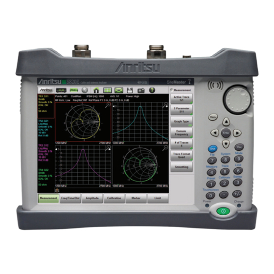
Screen images in this User Guide are illustrations of typical instrument features. Some images may include instruments other Note than the Site Master S820E. Traces and other display features may differ from the screen displays of your instrument. S820E UG... - Page 166 Trace 1 (TR1) Magnifying Glass, to maximize size of trace Trace 2 (TR2) Submenu Button (Key) Labels Main Menu Button (Key) Labels Trace 4 (TR4) Trace 3 (TR3) Figure 6-1. VNA Mode Display Overview PN: 10580-00343 Rev. F S820E UG...
-
Page 167: Chapter Overview
Chart, Real Impedance, and Imaginary Impedance are available in the S820E in addition to the standard graph types, Log Mag, SWR, Phase, and Smith Chart. The S820E gives you the ability to display four traces overlaid, or they can be displayed in individual graphs. -
Page 168: S-Parameters
2 and is received at port 1. : Reverse Reflection represents the measurement in which the incident signal is transmitted from port 2 and is reflected back to port 2. PN: 10580-00343 Rev. F S820E UG... -
Page 169: Calculating And Displaying S-Parameters
0 degrees area that is used as the phase reference. The S820E supports the following display types. Each type is associated with a particular S-parameter:... -
Page 170: Log Magnitude / 2
Real and Imaginary Real part of the complex S-parameter S Real Imaginary part of the complex S-parameter S Imaginary Applications Use the Real and Imaginary graph types to measure the elements of the complex S-parameter S PN: 10580-00343 Rev. F S820E UG... -
Page 171: Swr
Smith Chart = graphical tool for plotting impedance or admittance data versus frequency Applications Use Smith Chart with S or S to plot the input or output impedance of the DUT. Use the Inverted Smith Chart to plot admittance data. S820E UG PN: 10580-00343 Rev. F... -
Page 172: Phase Versus Unwrapped Phase Graph Types
Also, the first data point must be low enough in frequency so that its phase is less than 180 degrees from DC, otherwise the unwrapped phase measurement will have errors. Figure 6-2. Unwrapped Phase Compared with Phase PN: 10580-00343 Rev. F S820E UG... -
Page 173: Display Capabilities
Perform the following steps to observe the trace format features: 1. The default view (after preset) uses Trace Format = Quad with Number of Traces = 4. Refer to Figure 6-3. Figure 6-3. Format = Quad, Traces = 4 S820E UG PN: 10580-00343 Rev. F... - Page 174 2. Beginning with the default view, set Trace Format = Single, with Number of Traces = 4. Notice how all 4 traces are overlaid on a single graph. Refer to Figure 6-4. Figure 6-4. Format = Single, Traces = 4 6-10 PN: 10580-00343 Rev. F S820E UG...
- Page 175 TR1 (Trace 1) and TR3 are assigned to the top graph. TR2 and TR4 are assigned to the bottom graph. Refer to Figure 6-5. Figure 6-5. Format = Dual, Traces = 4 S820E UG PN: 10580-00343 Rev. F 6-11...
- Page 176 4. Next change Trace Format to Tri. Note how the 4 traces are assigned on this display. TR3 and TR4 are now overlaid in the bottom half of the display area. Refer to Figure 6-6. Figure 6-6. Format = Tri, Traces = 4 6-12 PN: 10580-00343 Rev. F S820E UG...
- Page 177 Number of Traces from 4 to 1. Note how the top left quadrant is filled, while the other three quadrants have no data. Refer to Figure 6-7. Figure 6-7. Format = Quad, Traces = 1 S820E UG PN: 10580-00343 Rev. F 6-13...
- Page 178 Regardless of the Trace Format that is selected, the number of traces that are displayed is controlled by the Number of Traces submenu key. For a brief description, refer to the examples in section “Trace Format and Number of Traces” on page 6-21. 6-14 PN: 10580-00343 Rev. F S820E UG...
-
Page 179: Active Trace And Markers
For greater precision, you can maximize the trace (with the “Magnifying Glass” icon) before moving the marker. S820E UG PN: 10580-00343 Rev. F 6-15... - Page 180 You cannot move a marker with the Arrow Keys or the rotary knob. When the Marker Menu is Displayed: You can then move the active marker by touch, by keypad entry, by Arrow Key, or by rotary knob. 6-16 PN: 10580-00343 Rev. F S820E UG...
-
Page 181: Vna Mode Menus
Cable List Marker to Mark ker to Peak Single Cable Loss Marker to ker to Valley Segmented Prop Velocity rop Velocity Windowing Windowing Nominal Side ominal Side Lobe Lobe Figure 6-9. Main Menu Keys S820E UG PN: 10580-00343 Rev. F 6-17... -
Page 182: Sweep Menus
Ref Plane Los ss s Sweep Averaging Ref Plane Loss Ref Plane Los Prop Velocity Power Setup Prop Velocity Port 2 Config Port 1 Config Port 2 Config Figure 6-10. Sweep Menu Keys 6-18 PN: 10580-00343 Rev. F S820E UG... -
Page 183: Trace Menus
Data Math Data a Ma Trace Only Trace O None Memory Only Trace - Mem Trace & Trace + Mem Memory Trace * Mem Trace / Mem Figure 6-11. Trace Menu Keys S820E UG PN: 10580-00343 Rev. F 6-19... -
Page 184: Measurement Menu
% submenu key or the Enter key. To turn smoothing Off, set its value to 0 %. Figure 6-12. Measurement Menu 6-20 PN: 10580-00343 Rev. F S820E UG... -
Page 185: Trace Format And Number Of Traces
If 1 trace is displayed in Dual, Tri, or Quad format, then that trace is displayed in the first quarter section of the sweep window, and any other sections are blank. S820E UG PN: 10580-00343 Rev. F 6-21... -
Page 186: Graph Type List Box
6-7 Measurement Menu VNA Mode Graph Type List Box Figure 6-13. Graph Type List Box 6-22 PN: 10580-00343 Rev. F S820E UG... -
Page 187: Freq/Dist Menu
DTF Aid: Opens the DTF Aid dialog box (see Figure 3-5 on page 3-10). This interactive parameter box allows setting multiple parameters and displays maximum testing distance DTF Setup and resolution. Figure 6-14. Frequency/Distance Menu (1 of 2) S820E UG PN: 10580-00343 Rev. F 6-23... -
Page 188: Freq/Dist Menu (Continued)
Enter. See Figure 6-16 on page 6-25 for the waveguide submenu keys. Windowing: Opens the “Windowing Menu” on page 6-27. Figure 6-15. Frequency/Distance Menu (2 of 2) 6-24 PN: 10580-00343 Rev. F S820E UG... - Page 189 DUT Line Type UT Line Type Coax Waveguide W W a a a v v v eguide List List Waveguide Loss Cutoff Freq Figure 6-16. Waveguide Submenu Keys S820E UG PN: 10580-00343 Rev. F 6-25...
-
Page 190: Cable And Waveguide List Boxes
6-8 Freq/Dist Menu VNA Mode Cable and Waveguide List Boxes Figure 6-17. Cable and Waveguide List Boxes 6-26 PN: 10580-00343 Rev. F S820E UG... -
Page 191: Windowing Menu
Low Side main lobe resolution (good). Minimum Side Lobe: Minimum Side Lobe Windowing shows the lowest side lobe levels (best) but the least main Minimum Side Lobe lobe resolution (worst). Figure 6-18. Windowing Menu S820E UG PN: 10580-00343 Rev. F 6-27... -
Page 192: Amplitude Menu
Smith Chart calculations to either 50 Ω or 75 Ω. The reference impedance determines the value of impedance at the center of the Smith Chart. This submenu key is displayed only when a Smith Chart trace is active. Figure 6-19. Amplitude Menu 6-28 PN: 10580-00343 Rev. F S820E UG... -
Page 193: Calibration Menu
Off: Hides all markers and the marker table. Marker Preset: Turns off all markers except for Marker 1. Sets Marker 1 location to the middle of the sweep. Marker Preset Marker Search Figure 6-20. Marker Menu (1 of 2) S820E UG PN: 10580-00343 Rev. F 6-29... - Page 194 Marker to Marker to Valley: Places the currently active marker on the Valley lowest signal amplitude currently displayed on screen. Figure 6-21. Marker Menu (2 of 2) 6-30 PN: 10580-00343 Rev. F S820E UG...
-
Page 195: Limit Menu
Limit Preset: Turns the limit line off and clears amplitude Limit Preset Limit Preset information. The next time that a limit line is turned on, it will be displayed at the default location (center of the display). Figure 6-22. Limit Menu S820E UG PN: 10580-00343 Rev. F 6-31... -
Page 196: Limit State Menu
Off: Press this key to turn off limit lines. Single: Press this key to create or move a single limit line. Single Segmented: Press this key to create or edit segmented limit Segmented lines. Figure 6-23. Limit State Menu 6-32 PN: 10580-00343 Rev. F S820E UG... -
Page 197: Edit Segments (Limit) Menu
Delete: Press this key to delete the selected limit segments. Close (ESC) Close (ESC): Press this key (or press the Esc key) to close the Segments menu and return to the Limit menu. Figure 6-25. Limit Line Segments Menu S820E UG PN: 10580-00343 Rev. F 6-33... - Page 198 6-13 Limit State Menu VNA Mode Edit Limit Values Dialog Box Figure 6-26. Edit Limit Values Dialog Box 6-34 PN: 10580-00343 Rev. F S820E UG...
-
Page 199: Sweep Menu 1
(1 to 1000). Use the number keypad, the Up/Down Arrow Power Setup keys, or the rotary knob, then press Enter. Port 1 Config Port 2 Config Figure 6-27. Sweep Menu – Sweep Setup S820E UG PN: 10580-00343 Rev. F 6-35... -
Page 200: Sweep Trigger Menu
Ext. Trigger: Sets the sweep trigger to an external source. Each sweep is activated by a TTL signal at the External Trigger In connector. Refer to “Test Panel Connector Overview” on page 2-3. Figure 6-28. Sweep Trigger Menu 6-36 PN: 10580-00343 Rev. F S820E UG... -
Page 201: Ifbw
If Immunity is set to Low during a normal measurement, then the instrument will be more susceptible to interfering signals. Interfering signals can make the measurement look better or worse than it really is. S820E UG PN: 10580-00343 Rev. F 6-37... -
Page 202: Sweep Menu 2
RF Pwr In Hold to Off. Power at the port is resumed when the Run/Hold setting is toggled back to Run. This is useful when you may not want a signal radiating out of the port at all times. 6-38 PN: 10580-00343 Rev. F S820E UG... -
Page 203: Sweep Menu 3
Examples: 1 = speed of light, and 0.5 = 1/2 the speed of light. Figure 6-30. Sweep Menu – Port 1 Config or Port 2 Config S820E UG PN: 10580-00343 Rev. F 6-39... - Page 204 S-parameter the reference plane extension should be applied. The calculated distance value or time value for each port is displayed in the Instrument Settings Summary above the graph area. Figure 6-31. Message Boxes for Reference Plane Extension 6-40 PN: 10580-00343 Rev. F S820E UG...
- Page 205 Instrument Settings Summary above the graph area. When you enter a time or distance value, a Units menu is provided (as shown in Figure 6-32). Figure 6-32. Manual Reference Plane Extension Entry with Time Units S820E UG PN: 10580-00343 Rev. F 6-41...
-
Page 206: Trace Menu
Trace & Memory: If a trace is stored in memory, then Trace & the stored trace (purple) and the current active trace Memory (yellow) are both displayed. Figure 6-33. Trace Menu (1 of 2) 6-42 PN: 10580-00343 Rev. F S820E UG... -
Page 207: Other Menus Keys
Figure 6-34. Trace Menu (2 of 2) 6-19 Other Menus Keys Refer to Table 2-1, “Site Master Keypad Functions” on page 2-9. S820E UG PN: 10580-00343 Rev. F 6-43... - Page 208 6-19 Other Menus Keys VNA Mode 6-44 PN: 10580-00343 Rev. F S820E UG...
-
Page 209: Chapter 7-Calibration, Vna
Screen images in this User Guide are illustrations of typical instrument features. Some images may include instruments other Note than the Site Master S820E. Traces and other display features may differ from the screen displays of your instrument. S820E UG... -
Page 210: Calibration Considerations
7-2 Calibration Considerations Calibration, VNA Calibration Considerations Various 2-port calibrations are available in the S820E in VNA Mode. Transmission response is the simplest and requires only one connection during calibration, but it does not correct for test port match errors. 1-Path 2-Port calibration requires four calibration connections and corrects for the transmit port match, but does not correct for the receive port. - Page 211 If you reduce only the number of points, then the frequency range is not changed. The S820E finds a subset of the original points in the sweep that can be used. You can therefore notice that the instrument may not use the exact number of points that you have entered.
- Page 212 7-2 Calibration Considerations Calibration, VNA Example of Calibration Benefits Figure 7-1. , and S Measurements before Calibration Figure 7-2. , and S Measurements after Calibration PN: 10580-00343 Rev. F S820E UG...
-
Page 213: Calibration Setup
The Cal Info window displays all of the key setup parameters for the calibration. The current settings are shown on the left, and the settings of the instrument at the time of the last calibration are shown on the right. S820E UG PN: 10580-00343 Rev. F... -
Page 214: Cal Type
Press the Cal Setup submenu button to choose a setup. In the Cal Setup menu, press the Edit Selection submenu button to choose a Cal Type. Figure 7-4. Cal Setup and Cal Type Dialog Box Notice the Cal Type description below the Cal Type selection list. PN: 10580-00343 Rev. F S820E UG... -
Page 215: Cal Line And Cal Method
7-3 Calibration Setup Cal Line and Cal Method The Site Master S820E supports measurements and calibrations for both coaxial and waveguide media. In the Cal Setup window, set the Cal Line to either Coax or Waveguide before starting the calibration. - Page 216 7-3 Calibration Setup Calibration, VNA Figure 7-5. Cal Line Setup PN: 10580-00343 Rev. F S820E UG...
-
Page 217: Port 1 Or Port 2 Dut And Cal Kit
Open and Short are also listed, as shown in Figure 7-7. For waveguide calibration kits, the Cutoff Frequency and the Offset Short 1 and Short 2 lengths are listed. Figure 7-6. Selection Window for Port 1 DUT Connector S820E UG PN: 10580-00343 Rev. F... - Page 218 Table 7-1, “Coax Dut Connectors and Cal Kits” on page 7-11 Table 7-2, “Waveguide DUT Connectors” on page 7-12 provide complete lists of Coax and Waveguide connectors and corresponding calibration kits that are selectable through the Cal Setup dialog box. 7-10 PN: 10580-00343 Rev. F S820E UG...
- Page 219 1091-55, Open TNC (female) 1091-56, Short TNC (female) 1015-54, Termination User 1: Coax User 1 (Coax) User 2: Coax User 2 (Coax) User 3: Coax User 3 (Coax) User 4: Coax User 2 (Coax) S820E UG PN: 10580-00343 Rev. F 7-11...
- Page 220 User 4: WG If you are using custom connectors that are not already listed, then the Site Master S820E allows you to create up to four User DUT connectors and corresponding User Cal Kits. Choose one of the User connectors from the...
- Page 221 Calibration menu. These can be found in the accessories section Caution of the S820E technical data sheet. Other Calibration kits that are not listed in the Calibration menu may be used provided you enter the correct required calibration coefficient information under one of the available custom User settings.
- Page 222 Selection window for the Port 1 DUT connectors, showing the list of custom User connectors available to the user. The name of the connectors can be edited as indicated on the screen. Figure 7-8. Cal Setup, Port 1 DUT Connectors 7-14 PN: 10580-00343 Rev. F S820E UG...
- Page 223 User 1 DUT coaxial connector. The corresponding cal kit parameters are shown and can be edited as indicated on the screen. Figure 7-9. Cal Setup, Port 1 DUT Coax Connector S820E UG PN: 10580-00343 Rev. F 7-15...
-
Page 224: Thru Device
Thru length offset of the cal kits that are used for Port 1 or Port 2, if applicable. Figure 7-10 shows the selection window for the Thru device setting. Figure 7-10. Thru Device Setting 7-16 PN: 10580-00343 Rev. F S820E UG... -
Page 225: Calibration Procedures
7. The calibration factors can be turned Off with the Cal Correction button. The calibration coefficients are saved and can be reapplied by setting Cal Correction back to On. S820E UG PN: 10580-00343 Rev. F 7-17... -
Page 226: Save And Recall Calibration Coefficients
Cal Correction is Off). The calibration information is recalled with a setup file and can be applied if the current internal instrument temperature is within the saved calibration window. Calibration information is not included when a measurement (.svna) file is saved. 7-18 PN: 10580-00343 Rev. F S820E UG... -
Page 227: Calibration Menu
Cal Correction On or Off. Turn Cal Correction On to apply the correction factor to the current measurement. For more details, refer to “Cal Correction” on page 7-20. Figure 7-12. Calibration Menu S820E UG PN: 10580-00343 Rev. F 7-19... - Page 228 When Cal Correction is On, the calibration coefficients are applied to the measured data, resulting in corrected S-parameter data. You can turn Cal Correction Off, which results in trace data using uncorrected (or raw) S-parameter data. 7-20 PN: 10580-00343 Rev. F S820E UG...
-
Page 229: Calibration Dialog Box
Calibration Dialog Box Key Sequence: Calibration > Start Calibration Figure 7-13. Calibration Dialog Box Measure: Starts the calibrations process. Follow the on screen instructions. Cal Setup: Press this submenu key to choose a calibration type. S820E UG PN: 10580-00343 Rev. F 7-21... -
Page 230: Start Calibration Menu
“Calibration Edit Selection Dialog Box” on page 7-23. Exit Setup: Press this submenu key to exit the setup Exit Setup screen and begin the calibration (by pressing Measure). Figure 7-14. Start Calibration Menu 7-22 PN: 10580-00343 Rev. F S820E UG... - Page 231 Calibration, VNA 7-5 Calibration Menu Calibration Edit Selection Dialog Box Key Sequence: Calibration > Start Calibration > Cal Setup > Edit Selection Figure 7-15. Calibration Edit Selection Dialog Box S820E UG PN: 10580-00343 Rev. F 7-23...
- Page 232 7-5 Calibration Menu Calibration, VNA 7-24 PN: 10580-00343 Rev. F S820E UG...
-
Page 233: Chapter 8-Vector Voltmeter
Introduction This chapter provides an overview of Vector Voltmeter or VVM Mode (Option 441). Vector Voltmeter Mode in the S820E provides a modern equivalent functionality to the classic analog Vector Voltmeter (VVM) instrument, which has been discontinued for many years. The classic analog VVM had 2 input channels (typically A and B), and both were capable of measuring voltage directly. -
Page 234: How The Vvm Function Works
Option 441 is a stand-alone option in the S820E and does not require the VNA Mode (Option 440) to provide full A/B and B/A ratio capability. All measurements made with Option 441 are based on CW signals. - Page 235 Vector Voltmeter instrument method (left) and the equivalent measurement capability integrated within the Site Master in VVM mode (right) when the S820E is used for a reflection measurement. Vector Voltmeter...
- Page 236 S820E is used for a transmission measurement. Vector Voltmeter Site Master Signal Generator (Left) Vector Voltmeter and (Right) S820E Site Master Equivalent Measurement 1 S820E Site Master 2 Coupler or Splitter 3 Signal Generator 4 Vector Voltmeter 5 Transmission Measurement 6 DUT (Device Under Test) Figure 8-2.
- Page 237 Vector Voltmeter 8-2 How the VVM Function Works A/B or B/A Measurements: For Reflection or Transmission measurements, the S820E VVM function can replace the entire setup of source, VVM, and couplers, as shown in Figure 8-1 Figure 8-2. If the measurement setup...
-
Page 238: Example B/A Measurement
Vector Voltmeter Example B/A Measurement The S820E in VVM mode can be used to measure the two ports of a splitter and compare them. 1. Connect a reference frequency to Port 1 of the S820E and to the input of... - Page 239 Press Save Reference to use this measurement as reference when you measure the other output side of the splitter. See Figure 8-5. Figure 8-5. First Side of Splitter Measured and Saved as Reference S820E UG PN: 10580-00343 Rev. F...
- Page 240 The difference between both outputs of the splitter is displayed as the Relative Value that is shown in green on the S820E screen. This is the error between the two outputs of the splitter. A properly working splitter should have very closely...
-
Page 241: Relative Measurements
The operations for relative measurements are described in the following steps. 1. Preset the S820E, then set up for this measurement by setting the frequency and the measurement type and format. Measurement format may be LogMag/Phase, LinMag/Phase, SWR, or Impedance. - Page 242 7. To create a new reference, press the Clear Reference submenu key, then press the Save Reference submenu key while measuring the DUT for which you want to capture the new reference values. 8-10 PN: 10580-00343 Rev. F S820E UG...
- Page 243 You can change the current reference without pressing the Clear Reference submenu key. When the current measurement is desired as the new reference, press the Save Reference submenu key. This completes the procedure for relative measurements. S820E UG PN: 10580-00343 Rev. F 8-11...
-
Page 244: Table Display Format
You can make a new row become the active row. Use the touch screen to tap a lock icon, or use the arrow keys or the rotary knob to highlight a row, then press Enter. 8-12 PN: 10580-00343 Rev. F S820E UG... - Page 245 As soon as you save another reference value, all of the relative measurement values are recalculated for stored measurements. Pressing Save Reference when a reference value is already saved, overwrites the saved reference with the new (current) value. S820E UG PN: 10580-00343 Rev. F 8-13...
- Page 246 Pressing Continue clears the data for that row, and the row becomes active with live data. After the live data are locked into that row, the next unused row in the table (if any remain) will become live, and the standard sequence returns. 8-14 PN: 10580-00343 Rev. F S820E UG...
- Page 247 Rows 1 through 4 have stored measurements (icons show locked). Row 5 is active and highlighted. Note that the measured values are identical except for Row 3. Figure 8-10. Working with Table Display Format – 1 of 3 S820E UG PN: 10580-00343 Rev. F 8-15...
- Page 248 Press Enter or tap the lock icon for Row 3. Then tap Continue to make Row 3 active. Note that previously saved data are overwritten with the current live data, as shown in Step Figure 8-11. Working with Table Display Format – 2 of 3 8-16 PN: 10580-00343 Rev. F S820E UG...
- Page 249 Press Enter to save the measurement in Row 3 and to make Row 5 active. Note that measurement data in Row 3 were stored, and all measurements are now identical. Figure 8-12. Working with Table Display Format – 3 of 3 S820E UG PN: 10580-00343 Rev. F 8-17...
- Page 250 Enter. If the lock icon was green, then the row becomes active immediately. If the lock icon was red, then the confirmation dialog box is displayed, and you must press Continue to unlock the row and overwrite its data. 8-18 PN: 10580-00343 Rev. F S820E UG...
-
Page 251: Vvm Calibration
VVM calibration removes system errors and may improve relative measurement results. For these reasons, when you are making relative measurements, VVM calibration is recommended, but it is not mandatory. S820E UG PN: 10580-00343 Rev. F 8-19... -
Page 252: A/B Or B/A Ratio Measurements
8-27) that allows you to recalibrate the Thru component without repeating the entire calibration sequence. Refer to “Thru Update” on page 4-15. For more specific calibration information, refer to Chapter 4, “Calibration, CAA”. 8-20 PN: 10580-00343 Rev. F S820E UG... -
Page 253: Vector Voltmeter Menus
RF Pwr In Hold Format Display Format lay Format Source Power Source Power Single Table Table High High g g h Save IFBW Reference Sweep Clear Averaging Reference Clear Table Figure 8-13. Main Menu Keys S820E UG PN: 10580-00343 Rev. F 8-21... -
Page 254: Measurement Menu (1 Of 2)
12 rows are available to display up to Single Table Table 12 measurements. Refer to section “Table Display Format” on page 8-12. Save Reference Clear Reference Clear Table Figure 8-14. Measurement Menu – 1 of 2 8-22 PN: 10580-00343 Rev. F S820E UG... -
Page 255: Measurement Menu (2 Of 2)
Table display format. The saved reference value remains saved to allow additional relative Clear Table measurements. This submenu key appears only when Display Format is set to Table. Figure 8-15. Measurement Menu – 2 of 2 S820E UG PN: 10580-00343 Rev. F 8-23... -
Page 256: Measurement Format
SWR displays the ratio (with no units) in the upper window only. Impedance measurement results are displayed as real impedance in the upper window, and as imaginary impedance in the lower window. 8-24 PN: 10580-00343 Rev. F S820E UG... -
Page 257: Single Display Format
Format setting. For Reflection and Transmission measurements in magnitude and phase formats, the measurement results are displayed as amplitude in the upper window and phase in the lower window. Figure 8-17. Single Display Format S820E UG PN: 10580-00343 Rev. F 8-25... -
Page 258: Frequency Menu
1 or 2 digits after the decimal point. The default setting is 1. Ref. Impedance Ref. Impedance Ref. Impedanc 50 Ω 75 Ω: Press this submenu key to toggle the reference impedance setting. The default setting is 50 Ω. Figure 8-19. Amplitude Menu 8-26 PN: 10580-00343 Rev. F S820E UG... -
Page 259: Calibration Menu
Cal Correction On Off: Press this submenu key to toggle the current calibration On or Off. A valid calibration must be available in order to turn on this setting. Figure 8-20. Calibration Menu S820E UG PN: 10580-00343 Rev. F 8-27... -
Page 260: Step 1 Calibration Dialog Box
8-12 Calibration Menu Vector Voltmeter Step 1 Calibration Dialog Box Figure 8-21. Calibration Step 1 of 5 8-28 PN: 10580-00343 Rev. F S820E UG... -
Page 261: Sweep Menu
The default setting is High, which is more accurate because you are measuring further above the noise floor. Use Low power for devices that are sensitive to higher power levels, such as amplifiers. Source Power is not applicable for A/B and B/A measurement types. S820E UG PN: 10580-00343 Rev. F 8-29... -
Page 262: Ifbw Dialog Box
8-13 Sweep Menu Vector Voltmeter IFBW Dialog Box Figure 8-23. IFBW Dialog Box 8-30 PN: 10580-00343 Rev. F S820E UG... -
Page 263: Preset Menu
8-18 System Menu Key Sequence: System (8) Refer to Section 11-8 “System Menu” on page 11-15. 8-19 Mode Menu Key Sequence: Mode Refer to Table 2-1, “Site Master Keypad Functions” on page 2-9. S820E UG PN: 10580-00343 Rev. F 8-31... - Page 264 8-19 Mode Menu Vector Voltmeter 8-32 PN: 10580-00343 Rev. F S820E UG...
-
Page 265: Chapter 9-High Accuracy Power Meter
Screen images in this User Guide are illustrations of typical instrument features. Some images may include instruments other Note than the Site Master S820E. Traces and other display features may differ from the screen displays of your instrument. S820E UG... - Page 266 Sensors are not included with the Site Master and must be purchased separately. The S820E Site Master data sheet lists compatible sensors. Note The SC8268 is not a compatible power sensor. It is not valid for use with High Accuracy Power Meter mode.
-
Page 267: Power Meter Display
Site Master. Relative Power (dB and %) or Absolute Power (dBm and Watts) Offset Value to Account for External Attenuation or Gain Source Frequency Used for Correction Factor Figure 9-1. Power Meter Display Overview S820E UG PN: 10580-00343 Rev. F... -
Page 268: General Measurement Setup Connection
9-3 General Measurement Setup Connection High Accuracy Power Meter General Measurement Setup Connection Refer to the label on the USB sensor for information on frequency Note range and dynamic range. RF IN Connection Setup for Anritsu High Accuracy S331AL SiteMaster Menu Terminating Sensors Enter Preset... -
Page 269: Connection And Offset
The current power level is centered with Min Value automatically set at 90 % of the current power and Max Value automatically set at 110 % of the current power. Refer to Figure 9-3 on page 9-6. S820E UG PN: 10580-00343 Rev. F... - Page 270 9-3 General Measurement Setup Connection High Accuracy Power Meter Before Autoscale After Autoscale Figure 9-3. Autoscale to Zoom In on a Measurement PN: 10580-00343 Rev. F S820E UG...
-
Page 271: Changing The Display Units
(see Figure 9-4 on page 9-8). 3. Any change in power will now be displayed relative to the set reference level. Refer to the bottom image in Figure 9-4 on page 9-8. S820E UG PN: 10580-00343 Rev. F... - Page 272 9-3 General Measurement Setup Connection High Accuracy Power Meter Relative First Power Level in dBm and mW First Power Level, Relative On Reduced Second Power Level, -6 dB (25%) of First Figure 9-4. Relative Power Example PN: 10580-00343 Rev. F S820E UG...
-
Page 273: Setting Upper And Lower Limits
• Green need and text: Limits are on and the current power level is within limits. • Red needle and text: Limits are on and the current power level is not within limits. Refer to Figure 9-5 on page 9-10 for examples of each condition. S820E UG PN: 10580-00343 Rev. F... - Page 274 9-3 General Measurement Setup Connection High Accuracy Power Meter Limits Turned Off (Yellow Needle, White Text) Power Level Within Limits (Green Text and Needle) Power Level Beyond Limits (Red Text and Needle) Figure 9-5. Limit Setting Display Changes 9-10 PN: 10580-00343 Rev. F S820E UG...
-
Page 275: Average Menu Options
Measurement Settings Summary area. 3. Connect the sensor to the Device Under Test. The High Accuracy Power Meter will now display the power level of the desired RF signal, with the residual noise removed. S820E UG PN: 10580-00343 Rev. F 9-11... -
Page 276: Ma24105A Inline Power Sensor
The reverse measurements are displayed below the numerical display of the forward measurements (Figure 9-6). To view all of the forward and reverse measurements in table format, use the Summary Table display (Figure 9-7). Figure 9-6. Power Meter View 9-12 PN: 10580-00343 Rev. F S820E UG... -
Page 277: Inline Sensor Setup
Up/Down Arrow keys or the touchscreen and press Edit. Several sensor settings are only appropriate for specific Note measurements. Refer to the on screen information in the Sensor Settings dialog for additional information. S820E UG PN: 10580-00343 Rev. F 9-13... - Page 278 Use the Up/Down keys, rotary knob or touchscreen to highlight the desired modulation type, and then press Select. Figure 9-9. Sensor Settings The selection of a specific modulation type provides a correction factor to refine the PEP calculation. 9-14 PN: 10580-00343 Rev. F S820E UG...
- Page 279 In the Sensor Settings dialog, highlight the CCDF Threshold ... row and press Edit. Set the desired value and press one of the units of measure buttons to complete. Figure 9-10. CCDF Threshold S820E UG PN: 10580-00343 Rev. F 9-15...
-
Page 280: Displayed Measurements
Display and/or Reverse Display under the Display main menu and choose a measurement. See Figure 9-8 for examples of measurement combinations. Refer to “Forward Menu” on page 9-28 “Reverse Menu” on page 9-29 additional information. Figure 9-11. Forward and Reverse Measurement Combinations 9-16 PN: 10580-00343 Rev. F S820E UG... -
Page 281: Summary View
Site Master instrument settings, DUT forward and reverse measurements, and sensor settings (Figure 9-12). Figure 9-12. Summary Table Modifying sensor settings is described in “Inline Sensor Setup” Note on page 9-13. S820E UG PN: 10580-00343 Rev. F 9-17... -
Page 282: Displaying Relative Power
2. Press the Fwd Relative and/or Rev Relative submenu keys. 3. Any change in either forward or reverse power is now displayed relative to the set reference level power. Refer to Figure 9-13. Figure 9-13. Forward and Reverse Relative Power 9-18 PN: 10580-00343 Rev. F S820E UG... -
Page 283: Limits For Forward And Reverse Measurements
• Green text: Limits are on and the current measured value is within limits. • Red text: Limits are on and the current measured value is not within limits. Figure 9-14. Measurement Value Beyond Reverse Limits Indicated by Red Text S820E UG PN: 10580-00343 Rev. F 9-19... -
Page 284: High Accuracy Power Meter Menus
Not available in Power Meter mode See Calibration Menu Refer to Chapter 9 Touchscreen Refer to Chapter 2 Refer to Chapter 2 Refer to Chapter 2 Figure 9-15. High Accuracy Power Meter Menus 9-20 PN: 10580-00343 Rev. F S820E UG... -
Page 285: Frequency Menu
Enter to complete the entry or, if entering a frequency using Measurement Frequency the keypad, press the appropriate units key. Pressing ESC while editing the frequency restores the previous setting. Figure 9-16. High Accuracy Power Meter Frequency Menu S820E UG PN: 10580-00343 Rev. F 9-21... -
Page 286: Amplitude Menu
Fullscale Fullscale: Adjusts the Top and Bottom values to their maximum allowed values (default settings). Figure 9-17. High Accuracy Power Meter Amplitude Menu 9-22 PN: 10580-00343 Rev. F S820E UG... -
Page 287: Calibration Menu
Zero Sensor: Initiates the zero calibration of the sensor. A message box is displayed with further instructions. Refer to “Calibration” on page 9-11 for additional information. Calibration Zero Sensor Figure 9-18. High Accuracy Power Meter Calibration Menu S820E UG PN: 10580-00343 Rev. F 9-23... -
Page 288: Average Menu
Average Mode: Toggles between single measurement and continuous measurements. In Single, each measurement (or series of measurements if Running Average is greater than 1) must be activated by the Run/Hold key. Figure 9-19. High Accuracy Power Meter Average Menu 9-24 PN: 10580-00343 Rev. F S820E UG... -
Page 289: Limit Menu
Lower Value used to enter new values, then press Enter to set the new values, or press the Esc button to restore the previous setting. Figure 9-20. High Accuracy Power Meter Limit Menu S820E UG PN: 10580-00343 Rev. F 9-25... -
Page 290: Ma24105A Menus
Relative Return Loss Rev Relative Rev Relative VSWR Forward Forwar Average Avera Power Powe Crest Factor Burst Average Manual Burst Average Auto Peak Envelope Power CCDF Figure 9-21. High Accuracy PM (MA24105A) Menus 9-26 PN: 10580-00343 Rev. F S820E UG... -
Page 291: Display Setup Menu
Summary Table: Displays a summary of Site Master Reverse everse instrument settings, USB sensor settings, and DUT forward Display isplay and reverse measurements (Figure 9-12). Summary Table Figure 9-22. High Accuracy PM (MA24105A) Display Setup Menu S820E UG PN: 10580-00343 Rev. F 9-27... -
Page 292: Forward Menu
CCDF: Press this submenu key to have the sensor measure the value of the Complementary Cumulative Distribution Function (CCDF). The CCDF describes the probability that the signal power is greater than a threshold value. Figure 9-23. High Accuracy PM (MA24105A) Forward Menu 9-28 PN: 10580-00343 Rev. F S820E UG... -
Page 293: Reverse Menu
Standing Wave Ratio (VSWR), which is another VSWR measurement of reflected energy caused by impedance mismatch. Expressed as a ratio of X:1. VSWR measures the voltage peaks and valleys. Figure 9-24. High Accuracy PM (MA24105A) Reverse Menu S820E UG PN: 10580-00343 Rev. F 9-29... -
Page 294: Frequency Menu
Enter to complete the entry or, if entering a frequency using Frequency the keypad, press the appropriate units key. Pressing ESC while editing the frequency restores the previous setting. Figure 9-25. High Accuracy PM (MA24105A) Frequency Menu 9-30 PN: 10580-00343 Rev. F S820E UG... -
Page 295: Amplitude Menu
Rev Relative was turned on. Rev Relative Rev Relative Note: The message Relative On shows in the message area when either Fwd or Rev Relative is on. Figure 9-26. High Accuracy PM (MA24105A) Amplitude Menu S820E UG PN: 10580-00343 Rev. F 9-31... -
Page 296: Calibration Menu
Zero Sensor: Initiates the zero calibration of the sensor. A message box is displayed with further instructions. Refer to “Calibration” on page 9-11 for additional information. Calibration Zero Sensor Figure 9-27. High Accuracy PM (MA24105A) Calibration Menu 9-32 PN: 10580-00343 Rev. F S820E UG... -
Page 297: Average Menu
Average Mode: Toggles between single measurement and continuous measurements. In Single, each measurement (or series of measurements if Running Average is greater than 1) must be activated by the Run/Hold key. Figure 9-28. High Accuracy PM (MA24105A) Average Menu S820E UG PN: 10580-00343 Rev. F 9-33... -
Page 298: Limit Menu
Up/Down Arrow keys. If the keypad was used to enter new values, then press Enter to set the new setting or press the Esc button to restore the previous setting. Figure 9-29. High Accuracy PM (MA24105A) Limit Menu 9-34 PN: 10580-00343 Rev. F S820E UG... -
Page 299: Sweep Menu
This menu is not available in High Accuracy Power Meter measurement mode. 9-19 Trace Menu This menu is not available in High Accuracy Power Meter measurement mode. 9-20 Other Menus Keys Refer to Table 2-1, “Site Master Keypad Functions” on page 2-9. S820E UG PN: 10580-00343 Rev. F 9-35... - Page 300 9-20 Other Menus Keys High Accuracy Power Meter 9-36 PN: 10580-00343 Rev. F S820E UG...
-
Page 301: Chapter 10-File Management
Chapter 10 — File Management 10-1 Introduction This chapter reviews the file management features of the Site Master S820E and describes the File menu and Save menu. The submenus under these menus allow you to save, rename, recall, copy, and delete files in internal memory or files on an external USB flash drive. -
Page 302: Overview
• Use the Left Arrow key to move out of a folder. • Use the Right Arrow key to move inside of a highlighted folder. • Press Esc to return to the previous screen. 10-2 PN: 10580-00343 Rev. F S820E UG... -
Page 303: File Types
File Management 10-3 File Types 10-3 File Types Filename extensions that are used in the Site Master S820E: • *.dat for Cable and Antenna measurement files • *.hipm for High Accuracy Power Meter measurement files • *.svna for VNA mode measurement files •... -
Page 304: Saving Files
Save File and Close Delete Filename Character Key EZ Name Keys. Refer to “EZ Name Matrix” on page 10-11. Symbols and Numbers Keyboard Letters Keyboard Shift Key Figure 10-1. Save Menu (1 of 2) 10-4 PN: 10580-00343 Rev. F S820E UG... - Page 305 Current Save Location. Tap to Change. Refer to “Setting the Save Location” on page 10-6. Current Filetype. Tap to Change. Refer to “Setting the File Type” on page 10-9. Figure 10-1. Save Menu (2 of 2) S820E UG PN: 10580-00343 Rev. F 10-5...
-
Page 306: Setting The Save Location
Site Master USB Type-A connector (Figure 2-1) and double tap on DRIVE: (Figure 10-2) to display the top navigation level showing both the internal memory and the external USB drive (Figure 10-3 on page 10-7). 10-6 PN: 10580-00343 Rev. F S820E UG... - Page 307 The Right Arrow key moves into the directory or folder, and the Left Arrow key moves out of the directory or folder. The Up and Down Arrow keys may be used to scroll through multiple files within any folder. S820E UG PN: 10580-00343 Rev. F 10-7...
- Page 308 10-4 Saving Files File Management Figure 10-4. Save Location is set to root directory in External USB Drive Folders and subfolders can be created and renamed in either Note storage location. 10-8 PN: 10580-00343 Rev. F S820E UG...
-
Page 309: Setting The File Type
Screen shot (.png) files are typically saved for reporting. The files contain a screen capture of the current display. The “look” of the file is set using the “Display/Audio Menu” on page 11-21. Figure 10-5. Set the File Type S820E UG PN: 10580-00343 Rev. F 10-9... -
Page 310: Choosing The File Name
(#1, #2, and so forth). Press Save or Enter to save the file. A Filetype extension (Figure 10-5) is automatically added to the Note Filename based on the chosen Filetype. 10-10 PN: 10580-00343 Rev. F S820E UG... -
Page 311: Ez Name Matrix
The top button toggles the separator on or off. The button below allows you to choose between using a dash “-” or an underscore “_” as the separator. Note Naming Examples: Separator Off: Site AAlphaColor CodeRLShort700 Separator On: Site A-Alpha-Color Code-RL-Short-700 Site A_Alpha_Color Code_RL_Short_700 S820E UG PN: 10580-00343 Rev. F 10-11... -
Page 312: File Management
10-4 Saving Files File Management EZ Name Buttons EZ Name Page 1 Matrix EZ Name Button Separator Keys EZ Name Page 2 Matrix Figure 10-6. EZ Name Matrix 10-12 PN: 10580-00343 Rev. F S820E UG... - Page 313 Figure 10-7. Renaming a Matrix Key 2. When you press Done, the new name is displayed in the Matrix (Figure 10-8). Figure 10-8. Renamed Matrix Key 3. Continue with renaming additional matrix keys as desired. S820E UG PN: 10580-00343 Rev. F 10-13...
- Page 314 A user-defined EZ Name matrix is saved in internal memory and will be available for future use until the custom file is deleted, or a Note Master Reset is performed. Refer to the “Preset Menu” on page 11-27 for additional information. 10-14 PN: 10580-00343 Rev. F S820E UG...
-
Page 315: Saving
1. After setting the location and file type, press Save. 2. The selected location and file type is now set for saving additional files. Anritsu recommends creating a new folder for each test site and saving all of the measurements for that specific site in the created folder. -
Page 316: Recalling Files
Only one file (of any type) can be recalled at a time. Recalling a Measurement From the File menu, press the Recall submenu key, select the measurement with the touchscreen, rotary knob, or the Up/Down Arrow keys, and then press Enter. 10-16 PN: 10580-00343 Rev. F S820E UG... - Page 317 10-5 Recalling Files Recalled measurements are first displayed on the Site Master as a preview. Figure 10-11 shows the preview of a saved cable loss measurement, S820E CL #1.dat. Figure 10-11. Preview of a Recalled Measurement Press Enter to complete recalling the measurement...
- Page 318 Up/Down Arrow keys, and then press Enter. See Figure 10-13 on page 10-18, an example screen-shot image. Press Esc to return to the File Recall menu. Figure 10-13.Preview of a Recalled ScreenShot 10-18 PN: 10580-00343 Rev. F S820E UG...
-
Page 319: Renaming Files
In this example, we change the short measurement name (that is automatically created by the Site Master) to a longer name typical of carrier requirement (Figure 10-15). Use the “EZ Name Matrix” on page 10-11 for this type of renaming. S820E UG PN: 10580-00343 Rev. F 10-19... - Page 320 10-5 Recalling Files File Management Rename file from: S820E CL #5.dat to: Site B-Gamma-RED-DTF-CL-Load-900-.dat. Same file after renaming Figure 10-15.Renamed File (Same Modification Date) 10-20 PN: 10580-00343 Rev. F S820E UG...
-
Page 321: Copying And Pasting Files
10-5 Recalling Files Copying and Pasting Files The Site Master S820E allows multiple files and folder to be copied at the same time. The example below describes copying several files and folders from internal memory to an external flash drive. - Page 322 Figure 10-17.Paste Selection Dialog Box Copy, Paste, Delete, and Create Folder buttons are duplicated Note under File Mgmnt, Recall, and Save submenus for your convenience. Figure 10-18.Files Pasted to the External USB Drive 10-22 PN: 10580-00343 Rev. F S820E UG...
- Page 323 8. After pasting is completed the USB drive can be removed. No type of “Eject” command is required to remove the drive. Files are removed from Site Master clipboard memory after Note pasting. The Site Master does not allow concurrent pasting. S820E UG PN: 10580-00343 Rev. F 10-23...
-
Page 324: Deleting Files
10-5 Recalling Files File Management Deleting Files The Site Master S820E allows multiple files and folder to be deleted at the same time from either internal memory or an external USB drive. The Delete button (after user confirmation) will delete all selected Warning files, even files not created by the Site Master. -
Page 325: Creating A Folder
Figure 10-21.Confirm File Deletion Creating a Folder The Site Master S820E allows folders to be created in either internal memory or an external USB drive. Multiple subfolders can also be created. This functionality is helpful in organizing traces by date, technician, carrier, and/or site location. - Page 326 Creating a new folder does not also set the folder as the current Note save location (displayed in the bread crumb). Refer to “Setting the Save Location” on page 10-6 for additional information. 10-26 PN: 10580-00343 Rev. F S820E UG...
-
Page 327: File Menu Overview
\ \ \ I I nternal\ Delete Navigation Paste Choose a storage drive. Navigation Delete Internal Bottom Navigation Bottom Page Up Page Up Page Down Bottom Page Down Page Up Page Down Figure 10-24.File Menu Keys S820E UG PN: 10580-00343 Rev. F 10-27... -
Page 328: File Menu
Many of the file management functions are duplicated in the Save and Recall menus for customer convenience. Figure 10-25.File Menu 10-28 PN: 10580-00343 Rev. F S820E UG... -
Page 329: Save Menu
(.stp) Setup (.stp) ScreenShot (.png) ScreenShot S2P (.s2p) (.png) Text (.txt) CSV (.csv) When one of these submenu keys is pressed, focus returns to the Save menu. Figure 10-26.Save Menu (1 of 3) S820E UG PN: 10580-00343 Rev. F 10-29... -
Page 330: Save Menu (Continued)
Use the check-box column to select multiple items to delete. Caution: After an item is deleted, it cannot be recovered. Figure 10-27.Save Menu (2 of 3) 10-30 PN: 10580-00343 Rev. F S820E UG... -
Page 331: Save Menu (Continued)
Page Up: Press this submenu key to page upward through Bottom the list. Page Down: Press this submenu key to page downward Page Up through the list. Page Down Figure 10-28.Save Menu (3 of 3) S820E UG PN: 10580-00343 Rev. F 10-31... -
Page 332: Recall Menu
(or both) that are selected. Only files or folders from one location can be deleted at a time. Use the check-box column to select multiple items to delete. After an item is deleted it cannot be recovered! Figure 10-29.Recall Menu (1 of 2) 10-32 PN: 10580-00343 Rev. F S820E UG... -
Page 333: Recall Menu (Continued)
Page Up: Moves up one screen of items (7 rows) in the current location. Page Up Page Down: Moves down one screen of items (7 rows) in the current location. Page Down Figure 10-30.Recall Menu (2 of 2) S820E UG PN: 10580-00343 Rev. F 10-33... -
Page 334: File Mgmnt Menu
Page Up: Moves up one screen of items (7 rows) in the current location. Page Down: Moves down one screen of items (7 rows) in the current location. Figure 10-31.File Management Menu 10-34 PN: 10580-00343 Rev. F S820E UG... -
Page 335: Chapter 11-System Operations
Screen images in this User Guide are illustrations of typical instrument features. Some images may include instruments other Note than the Site Master S820E. Traces and other display features may differ from the screen displays of your instrument. S820E UG PN: 10580-00343 Rev. -
Page 336: Self Test
If the Site Master is within the operating temperature range with a charged battery and fails the self test, then contact your Anritsu Service Center (http://www.anritsu.com/Contact.asp). To start a self test when the system is already powered up: 1. -
Page 337: Touchscreen Menu
Arrow keys, and the ability to lock out the touchscreen. Refer to the instructions shown in Figure 11-2 and the additional details provided in Figure 11-3 on page 11-4. Figure 11-2. Touchscreen Control S820E UG PN: 10580-00343 Rev. F 11-3... - Page 338 The Site Master can continue to be used to make measurements and save files (even with touchscreen locked or damaged) by using a USB mouse or by turning on the Arrow Cursor control. Figure 11-3. Touch Menu 11-4 PN: 10580-00343 Rev. F S820E UG...
-
Page 339: Help Menu
System Function Tool Bar Help icon displays options to view information about the instrument status, Site Master Frequently Asked Questions (FAQ), or the Instrument User Guide (Figure 11-4). Figure 11-4. Main Help Menu Screen S820E UG PN: 10580-00343 Rev. F 11-5... - Page 340 Package Version (in the Software Info column) is the current firmware version. Press Esc or to close and return to the main help menu screen. Press Esc or a second time to exit the help menu. 11-6 PN: 10580-00343 Rev. F S820E UG...
- Page 341 Classic and Advanced Cable-Antenna Analyzer modes (Figure 11-6). Scroll through the .html files using the touchscreen navigation aids on the top and bottom of each screen. Figure 11-6. FAQ File S820E UG PN: 10580-00343 Rev. F 11-7...
- Page 342 Press Esc or a second time to exit the help menu. The S820E Site Master Arrow keys can be used to navigate through previously viewed screens. The Left Arrow key (...
- Page 343 Links to the TOC and a compiled index are also available. Press Esc or to close and to return to the main help menu screen. Press Esc or a second time to exit the help menu. S820E UG PN: 10580-00343 Rev. F 11-9...
-
Page 344: Updating The Site Master Firmware
The “Release History” link provides a summary of the firmware Note changes. 1. Click on the “Firmware Update for the Site Master S820E” link. 2. Click the “Download” button and then “Run”. After the download is complete, press “Run” again and follow the onscreen instructions. - Page 345 10. Software version information is displayed in the System Status dialog box. See Figure 11-5 on page 11-6. Do not remove power or turn off the instrument during the Warning firmware update to avoid potential serious damage to the instrument. S820E UG PN: 10580-00343 Rev. F 11-11...
-
Page 346: Screen Shot Capture
File (7) menu then Save and setting the Filetype to ScreenShot. Note Screen shots saved through the File Save Menu will be saved in the current save directory. Refer to Chapter 10 for additional information. 11-12 PN: 10580-00343 Rev. F S820E UG... - Page 347 11-6 Screen Shot Capture Settings: Image Capture Size: Full Screen Background Color: Standard Image header/footer: Header Settings: Image Capture Size: Graph Only Background Color: Inverted Image header/footer: Footer Figure 11-9. Screen Shot Settings S820E UG PN: 10580-00343 Rev. F 11-13...
-
Page 348: System Menu Overview
Type Configuration C C C C Configuration Re-run Self DHCP Static Test Diagnostics Enter Enter Enter Self Test Self Test Bottom Page Up Page Down Save to File Figure 11-10. System Menu Keys 11-14 PN: 10580-00343 Rev. F S820E UG... -
Page 349: System Menu
Option ption Configuration guration To enable new options, enter the Option Key or the file that is provided by Anritsu Customer Service. Refer to “Option Configuration Dialog Box” on page 11-17. Connectivity nectivity Diagnostics Figure 11-11. - Page 350 S S e e e e lf Test S820ESelfTest#X.txt. The .txt file can be copied to a USB memory device and viewed on a PC with a text reader or word processor. Figure 11-12. System Menu (2 of 2) 11-16 PN: 10580-00343 Rev. F S820E UG...
- Page 351 System Operations 11-8 System Menu Option Configuration Dialog Box Figure 11-13. Option Configuration Dialog Box S820E UG PN: 10580-00343 Rev. F 11-17...
-
Page 352: Status Menu
USB memory device and viewed on a PC with a text reader or word processor. Figure 11-14. Status Menu Pressing the Anritsu logo on the touchscreen also displays this Status menu. (Refer to item Figure 2-6 on page 2-14.) - Page 353 System Operations 11-8 System Menu Figure 11-15. System Status Dialog Box S820E UG PN: 10580-00343 Rev. F 11-19...
-
Page 354: Time And Date Menu
Time Zone Settings: Press to change the time zone and to select whether the system clock is automatically adjusted for daylight saving time. Press Enter to save the changes. Enter Figure 11-16. Time and Date Menu Figure 11-17. Date/Time Dialog Box 11-20 PN: 10580-00343 Rev. F S820E UG... -
Page 355: Display/Audio Menu
Enter key to accept the change. Enter: Press this key or the Enter key on the number keypad to apply changes that have been set in the other Display/Audio submenus. Figure 11-18. Display/Audio Menu S820E UG PN: 10580-00343 Rev. F 11-21... - Page 356 Daytime increases the contrast of the display and increases line thickness of traces. It is useful outdoors in bright light or other challenging viewing conditions. Nighttime sets the display to a darker red-tinted color scheme, useful in night-time viewing conditions. 11-22 PN: 10580-00343 Rev. F S820E UG...
- Page 357 Under Background Color:, select Inverted to remove the graph background color (useful for paper printing), or select Standard for the typical black background. Use Image Header/Footer: to select the location where the instrument model, name, and date stamp are displayed. S820E UG PN: 10580-00343 Rev. F 11-23...
-
Page 358: Gps Menu
After a valid sync the instrument time is reset based on the UTC time plus/minus the time zone offset. Refer to “Time Zone Settings” on page 11-20. Figure 11-20. GPS Menu Figure 11-21. GPS Info 11-24 PN: 10580-00343 Rev. F S820E UG... - Page 359 An exclamation mark (!) is appended to the GPS location data in Note screen captures when the instrument is using Last Fix instead of current GPS information. Figure 11-22. “(!)” Indicates Last Fix GPS Data S820E UG PN: 10580-00343 Rev. F 11-25...
-
Page 360: Ethernet Configuration Menu
Figure 11-25. The settings are saved once the Enter button Enter Enter is pressed. Figure 11-23. Ethernet Configuration Menu Figure 11-24. Ethernet Configuration Dialog - DHCP Figure 11-25. Ethernet Configuration Dialog - Static 11-26 PN: 10580-00343 Rev. F S820E UG... -
Page 361: Preset Menu
EZ key names, and custom cable types are not deleted. To delete all user files, press the Delete All User Files button and then press Yes to confirm. Continued on next page Figure 11-26. Preset Menu (1 of 2) S820E UG PN: 10580-00343 Rev. F 11-27... - Page 362 Refer to Section 11-5 “Updating the Site Master Firmware” on page 11-10 for additional information. Figure 11-26. Preset Menu (2 of 2) Figure 11-27. Delete Custom Files 11-28 PN: 10580-00343 Rev. F S820E UG...
- Page 363 The next step (if a preset does not resolve the issue) is a Factory Reset. This can be performed at power On by holding down the Esc key and then pressing the power button, or through the Preset (1) menu. S820E UG PN: 10580-00343 Rev. F 11-29...
- Page 364 11-9 Preset Menu System Operations 11-30 PN: 10580-00343 Rev. F S820E UG...
-
Page 365: Chapter 12-Battery Replacement
Screen images in this User Guide are illustrations of typical instrument features. Some images may include instruments other Note than the Site Master S820E. Traces and other display features may differ from the screen displays of your instrument. S820E UG PN: 10580-00343 Rev. -
Page 366: Site Master Battery
The battery can be charged using either the AC-DC Adapter or the DC adapter. Refer to Figure 2-8 on page 2-19 for a description of battery symbols. Use only Anritsu Company approved batteries, adapters, and Note chargers with this instrument. Pressing the battery icon... - Page 367 If the battery door does not latch closed, then the battery may be inserted incorrectly. Figure 12-2. Battery Compartment Anritsu Company recommends removing the battery for long-term Note storage of the instrument. When using the Automotive power outlet adapter, always verify...
- Page 368 To prolong the useful battery life, the internal charging circuit monitors the battery temperature. Normal charging occurs when the battery temperature is between 0 °C and 45 °C. Charging is paused when the battery temperature is beyond this range. 12-4 PN: 10580-00343 Rev. F S820E UG...
-
Page 369: Chapter 13-Anritsu Tool Box With Lst
Chapter 13 — Anritsu Tool Box with 13-1 Introduction This chapter provides a brief overview of the Anritsu Tool Box and the Line Sweep Tools program. For detailed information about Line Sweep Tools, refer to the program Help. S820E UG PN: 10580-00343 Rev. -
Page 370: Anritsu Tool Box
Anritsu folder. Then click on the Anritsu Tool Box shortcut to open the Anritsu Tool Box. After the Tool Box is open, move the mouse pointer over any of the application icons to view a short description of the application. -
Page 371: Install The Software
Place the Installation DVD in your computer and follow the on-screen instructions (Figure 13-2). Figure 13-2. Installing Anritsu Tool Box with Line Sweep Tools If the installer does not start automatically, then navigate to the DVD and run INSTALL.BAT (Figure 13-3). -
Page 372: Why Use Line Sweep Tools
13-4 Why use Line Sweep Tools? Anritsu Tool Box with LST The installation will start. Follow the on-screen instructions. The software is also available free of charge from the Anritsu web site: http://www.anritsu.com 13-4 Why use Line Sweep Tools? Line Sweep Tools is a program designed to increase productivity for people who work with dozens of Cable traces, Antenna traces, and Passive Intermodulation (PIM) traces every day. -
Page 373: Chapter 14-Anritsu Easytest Tools
14-1 Introduction easyTest Tools allows you to create a test sequence (.ett) file on a PC. The file can be copied to the S820E via a USB memory stick and opened from the Menu screen by pressing the easyTest icon. -
Page 374: Easytest Tools On The Pc
Windows XP, Windows Vista, and Windows 7. After installing and launching easyTest Tools, perform the following steps to create an easyTest (.ett) file on the PC that can be opened on the S820E Microwave Site Master. Create an easyTest File on the PC 1. - Page 375 Anritsu easyTest Tools 14-2 easyTest Tools on the PC Example of Setup in easyTest Tools on the PC How the Setup is Displayed on the S820E Site Master Figure 14-1. easyTest Tools on the PC and S820E S820E UG PN: 10580-00343 Rev. F...
-
Page 376: Easytest On The S820E
After an easyTest Tool test sequence has been created on a PC, use the following steps to transfer the file from a USB Memory stick into the instrument. 1. Insert the USB Memory stick with the easyTest (.ett) file in the S820E Site Master. 2. Press the Menu button. - Page 377 Anritsu easyTest Tools 14-3 easyTest on the S820E 4. Select the file on the USB Memory stick and press Recall or Enter (Figure 14-3). Alternatively, copy the file to internal memory and recall the file from that location. Immediately after the .ett file is recalled, the test sequence is executed.
- Page 378 14-3 easyTest on the S820E Anritsu easyTest Tools 14-6 PN: 10580-00343 Rev. F S820E UG...
-
Page 379: Appendix A-Instrument Messages
Appendix A — Instrument Messages Introduction This appendix provides additional details regarding messages displayed on the S820E Site Master. The text of the dialog boxes is shown below, listed in alphabetical order. Example Message: Message Shown in Instrument: Additional details or suggestions regarding the message. - Page 380 14. Hardware driver failed to load: One of the hardware drivers required has not loaded correctly. Perform a Factory Reset and then cycle the power to the instrument. If error message persists, call your Anritsu Service Center. 15. Loading USB Sensor ... : The USB power sensor has been detected and a connection is being established to this sensor.
-
Page 381: Introduction
If it fails, then a message box is displayed with more specific information about the failure. 23. Zero Sensor completed: The zeroing function performed on the attached USB power sensor has been completed. S820E UG PN: 10580-00343 Rev. F... - Page 382 A-1 Introduction Instrument Messages PN: 10580-00343 Rev. F S820E UG...
-
Page 383: Appendix B-Measurement Review
(Figure B-1). Line sweeping can measure the power losses in the system at the functional frequencies. Line sweeping measures system impedance and confirms whether the system meets carrier specifications. S820E UG PN: 10580-00343 Rev. F... - Page 384 Figure B-1. Cable and Antenna Line Sweeping The Site Master does not measure system linearity (PIM Testing). Note Anritsu also sells the PIM Master, which is available in several carrier bands. The PIM Master tests for passive inter-modulation. PN: 10580-00343 Rev. F...
-
Page 385: Why Measure
Return Loss: 10 dB 10% power reflected Incomplete Coverage S820E Enter Back Shift File System Mode Measure Trace Limit Calibrate Sweep Preset Power Charge Return Loss: 20 dB 1% power reflected Complete Coverage Figure B-2. Coverage Area S820E UG PN: 10580-00343 Rev. F... -
Page 386: Line Sweeping
Return Loss measurement (part of the trace is above the limit line). Figure B-4 on page B-5 is a Distance to Fault measurement of the same system. Figure B-3. Failed Return Loss Measurement PN: 10580-00343 Rev. F S820E UG... - Page 387 This is a typical measurement specified on new installations or main transmission line replacement, but it is not typically tested on existing systems. Note Cable Loss cannot be measured with an antenna connected. S820E UG PN: 10580-00343 Rev. F...
- Page 388 B-2 Measurement Overview Measurement Review 1 Average Cable Loss Figure B-5. Cable Loss Measurement PN: 10580-00343 Rev. F S820E UG...
-
Page 389: Calibration
Anritsu recommends allowing the S820E to warm up for at least 10 minutes to typical operation temperature before calibrating. The instrument will require a new calibration if the internal instrument temperature changes more than ±10 ºC after... -
Page 390: Measurement Review
DTF Return Loss or Short or Peak (DTF SWR) Open Good Cable & DTF Return Loss or Load Peak Connectors (DTF SWR) Good System Including DTF Return Loss or Antenna Peak Antenna (DTF SWR) PN: 10580-00343 Rev. F S820E UG... -
Page 391: Common Rf Terms
Appendix C, “Glossary” for additional definitions of common RF terms that may be associated with the use of an S820E Site Master. 3 dB rule: A 3 dB gain means twice (x2) the power. A 3 dB loss means half the power. - Page 392 15 dB Return Loss. The Site Master can measure either Return Loss or VSWR. Some carriers require that Return Loss is measured in VSWR. This is typically a pass/fail measurement. Watt: Unit of measure for power. B-10 PN: 10580-00343 Rev. F S820E UG...
-
Page 393: Standard Line Sweep Measurements
Return Loss is the measurement made when the antenna is connected at the end of the transmission line. This measurement provides an analysis of how the various components of the system are interacting. It provides an aggregate return loss of the entire system. S820E UG PN: 10580-00343 Rev. F B-11... - Page 394 This whole process of measurements and of testing the transmission line system is called Line Sweeping. Advanced measurements are described in Section 3-6 “Advanced Measurements” on page 3-23. They including Transmission (2-Port), Transmission (External Sensor), Smith Chart, and 1-Port Phase. B-12 PN: 10580-00343 Rev. F S820E UG...
-
Page 395: Appendix C-Glossary
Appendix C — Glossary Introduction This glossary provides definitions for common RF terms that may be associated with the use of an S820E Site Master. Glossary Terms 3 dB rule : The 3 dB rule provides a means to estimate relative power values. - Page 396 These points may be along a radio path, transmission line or other devices. Attenuator : Attenuator is a device specifically designed to decrease the magnitude of a signal transmitted through it. PN: 10580-00343 Rev. F S820E UG...
- Page 397 Bandwidth Ratio : Bandwidth Ratio is the ratio of two devices having differing bandwidths, not necessarily in the same frequency spectrum. S820E UG PN: 10580-00343 Rev. F...
- Page 398 (CCDF) is a method used to characterize the peak power statistics of a digitally modulated signal. The CCDF curve can be used to determine design parameters for CDMA systems (such as the amount of back-off to run in a power amplifier). PN: 10580-00343 Rev. F S820E UG...
- Page 399 The terms ’cellular phone’ or ’cell phone’ are used interchangeably to refer to wireless phones. Within the wireless industry, cellular is also used to refer to non-PCS products and services. S820E UG PN: 10580-00343 Rev. F...
- Page 400 CPM : Continuous Phase Modulation (CPM) is a phase modulation technique employing smooth transitions between signal states. This reduces sidelobe spectral energy and improves co-channel performance. CW : Continuous Wave (CW) PN: 10580-00343 Rev. F S820E UG...
- Page 401 1000. Common values of dB expressed in ratios: 0 dB = 1:1, 10 dB = 10:1, 20 dB = 100:1, 30 dB = 1000:1, -30 dB = 0.001:1 [or (1/1000):1]. S820E UG PN: 10580-00343 Rev. F...
- Page 402 DSP : Digital Signal Processing (DSP) DSRC : Dedicated Short Range Communications (DSRC): DSRC is a system that is intended for communications between two vehicles, or from one vehicle to a roadside network. Efer to IEEE 802.11p. PN: 10580-00343 Rev. F S820E UG...
- Page 403 Is a specific type of EEPROM (electrically erasable programmable read-only memory) that is erased and programmed in large blocks. S820E UG PN: 10580-00343 Rev. F...
- Page 404 F (the noise figure) is defined as the decibel value of the noise factor. = 10log (F) where log uses the base 10, or common log. T s formula is valid only then the input termination is at standard noise temperature. C-10 PN: 10580-00343 Rev. F S820E UG...
- Page 405 Return Loss. The Site Master can measure either Return Loss or VSWR. Some carriers require that Return Loss is measured in VSWR. This is typically a pass/fail measurement. Watt : Watt (w) is a unit of measure for power. S820E UG PN: 10580-00343 Rev. F C-11...
- Page 406 C-2 Glossary Terms Glossary C-12 PN: 10580-00343 Rev. F S820E UG...
- Page 407 ..1-7 S-parameters, VNA mode . 6-4 Anritsu service centers ..1-10 transmission meas ..3-24 arrow cursor control ..2-21 VVM transmission meas .
- Page 408 ... . 2-3 menu, CAA ... .4-18 contacting Anritsu ..1-1 create menu, HAPM .
- Page 409 VNA ....6-23 electrostatic discharge ..1-8 frequency erasing memory ... 1-12 calibration considerations 7-2 S820E UG PN: 10580-00343 Rev. F Index-3...
- Page 410 ....9-4 menu ....11-24 http, contacting Anritsu ..1-1 submenu key ..11-16 time and date settings .
- Page 411 VSWR . . . 3-4 links VVM ....8-9 contacting Anritsu ..1-1 memory S820E product page . 1-1, 1-4 erasing .
- Page 412 1-port ... . .3-28 descriptions . 6-4 trace math comparison . .3-28 S820E product page phase vs unwrapped phase (URL) ... . . 1-1, 1-4 description and image .
-
Page 413: Serial Number
VNA ... 6-36 system menu ..11-15, 11-16 self test ....11-2 S820E UG PN: 10580-00343 Rev. F Index-7... - Page 414 ..3-55 VVM example splitter B/A . . . 8-6 units setting display units ..9-7 unlock touch screen ..2-21 Index-8 PN: 10580-00343 Rev. F S820E UG...
- Page 415 ....3-12 web links contacting Anritsu ..1-1 S820E product page . 1-1, 1-4 windowing ....3-16 windowing menu .
- Page 416 W to W Index-10 PN: 10580-00343 Rev. F S820E UG...
- Page 418 Anritsu Company Anritsu utilizes recycled paper and environmentally conscious 490 Jarvis Drive inks and toner. Morgan Hill, CA 95037-2809 http://www.anritsu.com...
Need help?
Do you have a question about the S820E and is the answer not in the manual?
Questions and answers