Sign In
Upload
Manuals
Brands
Anritsu Manuals
Measuring Instruments
Microwave Site Master S820E
Anritsu Microwave Site Master S820E Manuals
Manuals and User Guides for Anritsu Microwave Site Master S820E. We have
2
Anritsu Microwave Site Master S820E manuals available for free PDF download: User Manual, Maintenance Manual
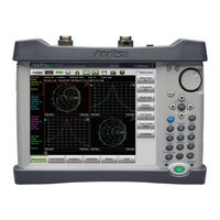
Anritsu Microwave Site Master S820E User Manual (438 pages)
Microwave Site Master Cable and Antenna Analyzer Featuring Classic and Advanced Modes
Brand:
Anritsu
| Category:
Analytical Instruments
| Size: 50 MB
Table of Contents
User Guide
1
Safety Symbols
7
Table of Contents
11
Chapter 1-General Information
23
Introduction
23
Contacting Anritsu
23
Document Conventions
24
Instrument Description
24
Available Options
26
Standard Accessories
26
Optional Accessories
26
URL for the Microwave Site Master S820E
26
Site Master Specifications
26
Battery Information
27
Calibration Requirements
28
Additional Documents
28
Preventive Maintenance
29
Annual Verification
29
ESD Caution
30
Soft Carrying Case
30
Tilt Bail Stand
32
Anritsu Service Centers
32
Secure Environment Workplace
33
Site Master Memory Types
33
Erase All User Files in Internal Memory
34
Usage in a Secure Environment
35
Chapter 2-Instrument Overview
39
Introduction
39
Turning on the Site Master
40
Test Panel Connector Overview
41
Front Panel Overview
43
Front Panel Keys
43
LED Indicators
49
Front Panel Interface
50
S820E UG PN: 10580-00343 Rev. H
51
Touchscreen Display Overview
52
Main Menu Keys
53
Submenu Keys
53
Submenu Button Types
55
Status Tool Bar
57
System Function Tool Bar
61
Dual Display Format
63
Display Modes
65
Calibration
67
Calibration Symbols
67
Chapter 3-Cable And Antenna Measurements
69
Standard Measurements
71
Return Loss or VSWR Measurement
72
Cable Loss Measurement
75
Distance-To-Fault (DTF)
77
Using DTF Aid
78
Transmission Line Selection
79
Distance Resolution
82
Windowing
84
Dmax (Maximum Usable Distance)
85
DTF Measurement Examples
86
Advanced Measurements
91
Transmission Measurements
91
Transmission (2-Port)
92
Transmission (Ext. Sensor)
94
Smith Chart
96
1-Port Phase
96
Measurement Setup
97
Frequency
97
Distance
97
Amplitude
97
Sweep
98
Limit Lines
102
Markers
108
Trace
115
Cable and Antenna Analyzer Menus
121
Measurement Menu
123
Freq/Dist Menu
126
Freq/Dist Menu (Continued)
127
Windowing Menu
128
Amplitude Menu
129
Calibration Menu
130
Marker Menu
131
Marker Menu (Continued)
132
Limit Menu
133
Limit State Menu
134
Limit Menu (Continued)
134
Sweep Menu
135
Sweep Trigger Menu
136
Trace Menu
137
Other Menus Keys
138
Chapter 4-Calibration, CAA
139
Introduction
139
Chapter Overview
139
Calibration Setup
141
Cal Type
142
Cal Line
145
Port 1 DUT and Cal Kit
146
Calibration Procedures
153
Calibration Procedure
153
Thru Update
154
Temperature Window
155
Save and Recall Calibration Coefficients
155
Interpolation
156
Calibrate Menu
157
Chapter 5-Classic Mode Operation
159
Introduction
159
Classic Mode and Advanced Mode
160
Menu Map - Classic Mode
162
Marker Menu
164
Marker Menu (Continued)
164
Limit Menu
166
Return Loss
167
DTF Return Loss
167
All Other Menus
168
Chapter 6-VNA Mode
169
Introduction
169
Chapter Overview
171
S-Parameters
172
Additional Examples
172
Calculating and Displaying S-Parameters
173
Log Magnitude
173
Log Magnitude / 2
174
Phase
174
Real and Imaginary
174
Swr
175
Group Delay
175
Smith Chart
175
Phase Versus Unwrapped Phase Graph Types
176
Display Capabilities
177
Flexible Features for Displaying Results
177
Active Trace and Markers
183
VNA Mode Menus
185
Sweep Menus
186
Trace Menus
187
Measurement Menu
188
Trace Format and Number of Traces
189
Graph Type List Box
190
Freq/Dist Menu
191
Start Frequency (F1)
191
Stop Frequency (F2)
191
Start Distance (D1)
191
Stop Distance (D2)
191
Freq/Dist Menu (Continued)
192
DTF Setup
192
Cable and Waveguide List Boxes
194
Windowing Menu
195
Amplitude Menu
196
Menu
196
Calibration Menu
197
Marker Menu
197
Marker Menu (Continued)
197
Limit Menu
199
Limit State Menu
200
Edit Segments (Limit) Menu
201
Sweep Menu 1
203
Sweep Trigger Menu
204
Ifbw
205
RF Immunity
205
Sweep Menu 2
206
RF Pwr in Hold
206
Sweep Menu 3
207
Trace Menu
210
Trace Menu (Continued)
210
Other Menus Keys
211
Chapter 7-Calibration, VNA
213
Introduction
213
Calibration Considerations
214
Calibration Data and Indications
214
Calibration Setup
217
Cal Type
218
Cal Line and Cal Method
219
Port 1 or Port 2 DUT and Cal Kit
221
Thru Device
228
Calibration Procedures
229
Calibration Procedure
229
Save and Recall Calibration Coefficients
230
Calibration Menu
231
Calibration Dialog Box
233
Start Calibration Menu
234
Chapter 8-Vector Voltmeter
237
Introduction
237
How the VVM Function Works
238
Example B/A Measurement
242
Relative Measurements
245
Table Display Format
248
VVM Calibration
255
VVM Calibration Versus Save Reference
255
Absolute VVM Measurements
255
Relative VVM Measurements
255
A/B or B/A Ratio Measurements
256
Performing Calibrations
256
Vector Voltmeter Menus
257
Measurement Menu (1 of 2)
258
Measurement Menu (2 of 2)
259
Measurement Format
260
Single Display Format
261
Frequency Menu
262
Amplitude Menu
262
Calibration Menu
263
Step 1 Calibration Dialog Box
264
Sweep Menu
265
Source Power
265
IFBW Dialog Box
266
Preset Menu
267
Trace Menu
267
Limit Menu
267
File Menu
267
System Menu
267
Mode Menu
267
Chapter 9-High Accuracy Power Meter
269
Introduction
269
Power Meter Display
271
General Measurement Setup Connection
272
Connection and Offset
273
Setting the Measurement Frequency
273
Setting the Amplitude
273
Changing the Display Units
275
Displaying Relative Power
275
Setting Upper and Lower Limits
277
Average Menu Options
279
Calibration
279
Zero Failure
279
MA24105A Inline Power Sensor
280
Introduction
280
Inline Sensor Setup
281
Displayed Measurements
284
Summary View
285
Displaying Relative Power
286
Limits for Forward and Reverse Measurements
287
High Accuracy Power Meter Menus
288
Frequency Menu
289
Amplitude Menu
290
Calibration Menu
291
Average Menu
292
Limit Menu
293
MA24105A Menus
294
Display Setup Menu
295
Forward Menu
296
Reverse Menu
297
Frequency Menu
298
Amplitude Menu
299
Calibration Menu
300
Average Menu
301
Limit Menu
302
Sweep Menu
303
Trace Menu
303
Other Menus Keys
303
Chapter 10-File Management
305
Introduction
305
Overview
306
File Types
307
Save Files
308
Set the Save Location
309
Set the File Type
312
Choose the File Name
313
EZ Name Matrix
314
Saving
317
Additional Menus
317
Recall Files
318
Recall a Measurement
318
Recall a Setup
320
Recall/Preview a Screen Shot
320
Recall a VIP Measurement (VIP Mode Only)
321
Recall a VIP Image (VIP Mode Only)
322
Rename Files
323
Copy and Paste Files
325
Delete Files
328
Create a Folder
329
File Menu Overview
331
File Menu
332
Save Menu
333
Save Menu (Continued)
334
Recall Menu
336
Recall Menu (Continued)
337
File Mgmnt Menu
338
Chapter 11-System Operations
339
Introduction
339
Self Test
340
Touchscreen Menu
341
Help Menu
343
Updating the Site Master Firmware
348
Screen Shot Capture
350
System Menu Overview
352
System Menu
353
Status Menu
356
Time and Date Menu
358
Display/Audio Menu
359
GPS Menu
362
Ethernet Configuration Menu
364
Preset Menu
365
Chapter 12-Battery Replacement
369
Introduction
369
Site Master Battery
370
Battery Replacement
370
Chapter 13-Anritsu Tool Box with LST
373
Introduction
373
Anritsu Tool Box
374
Install the Software
375
Why Use Line Sweep Tools
376
Chapter 14-Anritsu Easytest Tools
377
Introduction
377
Easytest Tools on the PC
378
Create an Easytest File on the PC
378
Easytest on the S820E
380
Chapter 15-Video Inspection Probe (VIP)
383
Introduction
383
Setup and Operation Summary
384
VIP Setup
385
Connect the VIP
385
Launch the VIP Application
386
VIP Test Settings
386
Operation
388
VIP Image Analysis
388
VIP Reporting
391
VIP Menus
393
Setup Menu
394
Measurement Menu
395
File Menu
396
Report Menu
397
Appendix A-Instrument Messages
399
A-1 Introduction
399
Introduction
401
Appendix B-Measurement Review
403
Introduction
403
Measurement Overview
403
What Is Measured
403
B-1 Introduction
403
Why Measure
405
Line Sweeping
406
Calibration
409
Measurement Review
410
Common RF Terms
411
Standard Line Sweep Measurements
413
Line Sweep Measurement Types
413
Appendix C-Glossary
415
Introduction
415
Glossary Terms
415
C-1 Introduction
415
Index
427
Advertisement
Anritsu Microwave Site Master S820E Maintenance Manual (88 pages)
Cable and Antenna Analyzer 1 MHz to 8/14/20/30/40 GHz
Brand:
Anritsu
| Category:
Measuring Instruments
| Size: 13 MB
Table of Contents
Table of Contents
3
Chapter 1-General Information
7
Introduction
7
Description
7
Standard Accessories
7
Related Documents
7
Options
7
Contacting Anritsu
7
Product Information, Compliance, and Safety
8
Recommended Test Equipment
8
Recommended Tools and Supplies
10
Replaceable Parts and Assemblies
11
Chapter 2- Performance Verification
15
Introduction
15
Manual Performance Test − Frequency Accuracy Verification
15
Equipment Required
15
Procedure
15
Automated Performance Tests
17
Test Sequence
17
Test Reports
17
Equipment Required for Automated Tests
18
S-Parameter Measurements Verification Test
20
Transmission Dynamic Range Verification
21
Transmission High Level Noise Verification
21
Automated Test Procedure
21
SC8268 Verification Procedure
22
Equipment Required
22
Procedure
22
Chapter 3-Battery Information
23
Introduction
23
Battery Pack Removal and Replacement
24
Battery Pack Information
26
Chapter 4-Assembly Removal and Replacement
27
Introduction
27
Electrostatic Discharge Prevention
27
Real Time Clock (RTC) Battery
27
Replaceable Parts, Assemblies, and Accessories
27
Instrument Case for Site Master S820E
28
Front and Back
28
Case Outer Components
29
Opening the Case
30
Basic Case Parts
32
Front Panel Components
33
Back Panel Components
34
Test Panel Connectors
35
Internal Anatomy of the Site Master S820E
36
Case Assembly Components with Complete PCB
36
Case Assembly Components with Motherboard PCB
37
Motherboard and Connector Panel
37
Motherboard and Connector Panel for Option S820E-0708
38
Motherboard and Connector Panel for Higher Frequency Options
39
4-8 Disassembly Sequence Overview
40
Disassembly Sequence Overview
40
Removal and Replacement Instructions
40
Replacements that Do Not Require Opening the Case
41
Removing the Bumpers
41
Removing the Battery Door and Battery
41
Removing and Replacing the Rotary Knob
42
Removing and Replacing the Tilt Bail
42
Opening the Instrument Case
43
Procedure
43
Closing the Case
48
Installing Battery
48
Restarting the Instrument
48
Main/Vna PCB and Connector Panel Removal
49
Procedure
50
Main/Vna PCB Assembly Installation
51
Procedure
52
Connector Panel Removal
53
Procedure
54
Assemblies" on Page
56
Section 4-11 "Closing the Case
56
Connector Panel Installation
56
Port Connector Removal
57
Procedure
57
Section 4-16 "Port Connector Removal
57
Port Connector Installation
59
Microwave Module Removal
60
Procedure
60
Section 4-18 "Microwave Module Removal
60
Microwave Module Installation
61
Dual Sampler Assembly Removal
62
Procedure
62
Section 4-20 "Dual Sampler Assembly Removal
62
Dual Sampler Assembly Installation
63
Fan Assembly Removal
64
Procedure
64
Section 4-22 "Fan Assembly Removal
64
Fan Assembly Installation
66
LCD Assembly Removal
68
Procedure
68
Section 4-24 "LCD Assembly Removal
68
Keypad PCB Removal
72
Procedure
72
Section 4-26 "Keypad PCB Removal
72
LCD Assembly Installation
72
Keypad Rubber Membrane and Keypad PCB Installation
74
Touch Screen Removal
75
Procedure
75
Section 4-28 "Touch Screen Removal
75
Touch Screen Replacement
76
Rotary Encoder Installation
77
Section 4-30 "Rotary Encoder Removal
77
Rotary Encoder Removal
77
Procedure
77
Speaker Installation
78
Section 4-32 "Speaker Removal
78
Speaker Removal
78
Chapter 5-Troubleshooting
79
Introduction
79
Turn-On Problems
79
Unit Cannot Boot up (Battery Powered)
79
Unit Cannot Boot up (AC Powered)
79
Unit Cannot Complete Boot-Up
79
Unit Boots with no Display
80
Operating Problems
80
Failed Instrument Self Test
80
Return Loss Trace Has Power Dropout When Port 1 Is Terminated with Short
81
Transmission Trace Has Power Dropout When Thru Cable Is Connected between VNA Ports5-3
81
Appendix A-Test Records
83
Introduction
83
A-1 Introduction
83
S820E Site Master Test Record
84
VNA Frequency Accuracy
84
VNA Measurements Accuracy Verification
84
VNA Transmission Dynamic Range
84
VNA High Level Noise (Trace Noise
84
SC8268 Verification
84
Troubleshooting
86
Advertisement
Related Products
Anritsu Site Master S810D
Anritsu Site Master S820D
Anritsu S810A
Anritsu S818A
Anritsu Site Master S331D
Anritsu Site Master S331P-0704
Anritsu Site Master S250A
Anritsu SM/PL
Anritsu SSV-h Series
Anritsu SSV-i Series
Anritsu Categories
Measuring Instruments
Test Equipment
Portable Generator
Control Unit
Thermometer
More Anritsu Manuals
Login
Sign In
OR
Sign in with Facebook
Sign in with Google
Upload manual
Upload from disk
Upload from URL