
Related Manuals for Anritsu Site Master


Summary of Contents for Anritsu Site Master
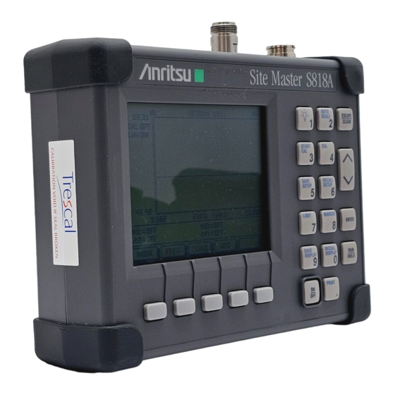
- Page 1 Site Master ™ S810A, S818A Antenna and Coax/Waveguide Analyzer User’s Guide Hand-Held Tester For Antennas, Transmission Lines And Other RF Components Color Cover P/N: 00986-00019...
- Page 2 WARRANTY The ANRITSU product(s) listed on the title page is (are) warranted against defects in materials and workmanship for one year from the date of shipment. ANRITSU’s obligation covers repairing or replacing products which prove to be defective during the warranty period. Buyers shall prepay transportation charges for equipment returned to ANRITSU for war- ranty repairs.
- Page 3 MANUAL ERRATA MANUAL: Title: Site Master S810A, S818A Antenna and Coax/ Waveguide Analyzer User’s Guide Part Number: 10580-00014 Rev. Ltr/Date: A / November 1997 ERRATA PACKET Part Number: 10901-00133 INSTRUCTIONS 1. Make the manual change listed below. ERRATA 1, December 1997 1.
-
Page 5: Table Of Contents
Storing a Display ....2-34 Recalling a Display ....2-35 November 1997 10580-00014 Copyright 1997, ANRITSU Co. Revision: A... - Page 6 Coax/Waveguide Loss Measurement . . . 2-35 Selecting a Frequency Range... . . 2-35 Performing a Calibration....2-36 Making a Measurement .
- Page 7 Software Tools Program ..3-1 Description ....3-1 Requirements ....3-1 Communication Port Setting.
- Page 8 How to Use this Manual The operation of the Site Master ™ is straightforward and intuitive. However, you may find it helpful to review the operation of the keys and menus prior to first-time use. Descriptions of the keys and menus, along with measurement proce- dures, are provided in Chapter 2.
- Page 9 Figure 1-1. Site Master System 1 - 0...
-
Page 10: General Information
(LCD) to provide a graphical indication of SWR or RL over the selected frequency range. The Site Master has a built-in distance-to- fault capability. The Site Master is capable of up to two hours of con- tinuous operation from a fully charged internal battery. It can also be operated from a 12.5 dc source (which will also simultaneously charge... -
Page 11: Standard Accessories
Master internal memory are down-loaded to the PC using the included serial cable. This null-modem serial cable connects between the Serial Interface connector on the Site Master and a Com Port on a DOS/ Windows-based PC. Once stored, the graphic trace can then be dis- played, scaled, and/or enhanced with markers and limit lines. -
Page 12: Options
Precision Universal Waveguide Calibration Components, see • Table A-1 Precision Coaxial-to-Universal Waveguide Adapters, see • Table A-2 RF Detector, 10 MHz to 20 GHz, N(m) input connector, • 50 Ohms, Part No. 560-7N50B Transit Case for Site Master, Part No. 760-213 • 1 - 3... - Page 13 Chapter 1 General Information HP Deskjet 340 Printer, Part No. 2000-766 • Serial-to-Parallel Converter Cable (use with the • HP 340 Printer), Part No. 2000-753 Seiko DPU-411 Thermal Printer, Part No. 2000-754 (U.S.) or • 2000-761 (Europe) Serial Interface Cable (use with the DPU-411 Printer), •...
-
Page 14: Performance Specifications
Performance Specifications (1 of 2) Specifications are valid when the unit is calibrated at ambient tem- perature after a 5 minute warmup. Description Value Frequency Range: Site Master S810A 3.3 to 10.5 GHz Site Master S818A 3.3 to 18.0 GHz ° Frequency Accuracy... - Page 15 * 2 ppm/ C from 25 C ** Fault location is accomplished by inverse Fourier Transformation of data taken with the Site Master. Resolution and maximum range depend on the number of frequency data points, frequency sweep range and relative propagation velocity of the cable or group velocity of the waveguide being tested.
- Page 16 Chapter 1 General Information This page is intentionally blank. 1 - 7...
- Page 17 Figure 2-1. Site Master Controls and Connectors 2 - 0...
-
Page 18: Operation
Charging charged. (Indicator automatically shuts off when the battery is fully charged.) External Indicator light to show that the Site Master is being Power powered by the external charging unit. Serial Provides an RS232 DB9 interface with a Com Port... -
Page 19: Keypad
Calls up the Scale Menu, described on page 2-12. MARKER Calls up the Markers Menu, described on page 2-21. Turns the Site Master on or off. When turned on, the system state at the last turn-off is restored If the ES- CAPE/CLEAR key is held down, the factory preset state is restored. - Page 20 0 will erase all saved displays. CAUTION:The selected memory location will be over- written by the SAVE DISPLAY operation. No warning is given. When the Site Master is cycled on/off, the memory location increment resets to the lowest memory loca- tion (1). SAVE...
- Page 21 “short” that you must attach to the end of the test port. Connect LOAD, Press ENTER The Site Master then measures the 50 termina- tion (load) that you must attach to the end of the test port. For Waveguide Calibration, follow the text in the...
- Page 22 Chapter 2 Operation Connect LOAD, Press ENTER The Site Master will measure the 50 termina- tion (load) that you must attach to the end of the test port. NOTE: The combined measurements of an open, a short, and a known-impedance load in coax calibration and...
-
Page 23: Soft Keys
Chapter 2 Operation Figure 2-2. Site Master Front Panel Display Layout Soft Keys Each of the soft keys has a corresponding soft key label area on the dis- play. The label identifies the function of the soft key for the current menu selection. - Page 24 Chapter 2 Operation Figure 2-3. Site Master Menu Structure 2 - 7...
- Page 25 Chapter 2 Operation Main Menu At turn on, the Main Menu soft keys, below, are dis- played, and the Marker status is shown in the mes- sage area. These soft keys provide the following menu selec- tions: MODE — Selects the type of measurement. Use the Up/Down Arrow key and ENTER key to se- lect the type of measurement in the FREQ, DTF, and POWER MONITOR measurement modes.
- Page 26 Chapter 2 Operation When the DTF measurement mode is selected, the Main Menu Main Menu soft keys, below, are displayed, and the Marker status is shown in the message area. These soft keys provide the following menu selec- tions: MODE — Selects the type of measurement. Use the Up/Down Arrow key and ENTER key to se- lect the type of measurement in the FREQ, DTF, and POWER MONITOR measurement modes.
- Page 27 Chapter 2 Operation Power When the Power Monitor measurement mode is se- Monitor lected, the Main Menu soft keys, below, are dis- Main Menu played, and the units, relative, offset, and zero adjust status are shown in the message area. UNITS —...
- Page 28 Chapter 2 Operation Frequency Provides for setting sweep frequency end-points. Se- Menu lected frequency values may be changed using the (FREQ) keypad or Up/Down Arrow key. All frequency en- tries are in GHz. Choosing FREQ causes the soft keys, below, to be displayed and the corresponding values to be shown in the message area.
- Page 29 Chapter 2 Operation Scale Menu Provides for changing the display scale. Selected (SCALE) values may be changed using the keypad or Up/Down Arrow key. Choosing SCALE causes the soft keys, below, to be displayed and the corresponding values to be shown in the message area.
- Page 30 Chapter 2 Operation Option Provides for selecting Site Master options. Menu (OPT) Choosing OPT causes the soft keys, below, to be dis- played and the corresponding values to be shown in the message area. B1 MATH — Opens a menu of trace math operation modes;...
- Page 31 Chapter 2 Operation Option Provides for selecting additional Site Master options. Sub-Menu Choosing MORE causes the soft keys, below, to be displayed and the corresponding values to be shown in the message area. B5 UNITS — Toggles between ENGLISH and METRIC units.
- Page 32 Chapter 2 Operation Distance Provides for setting Distance to Fault parameters. Menu Selected distance values may be changed using the (DIST) keypad or Up/Down Arrow key. Entry can be in feet or meters, depending on the setting of the B5 soft key in the Option Sub-Menu (page 2-15).
- Page 33 Chapter 2 Operation Distance Provides for setting the cable loss and relative propa- Sub-Menu 1 gation velocity of the coaxial cable. Selected values may be changed using the keypad or Up/Down Ar- row key. Choosing MORE causes the soft keys, below, to be displayed and the corresponding values to be shown in the message area.
- Page 34 Chapter 2 Operation Distance Provides for setting waveguide loss and cutoff fre- Sub-Menu 2 quency of the waveguide. Selected values may be changed using the keypad or Up/Down Arrow key. Chosing MORE causes the soft keys, below, to be displayed and the corresponding values to be shown in the message area.
- Page 35 Chapter 2 Operation NOTE: Using Windowing The theoretical requirement for inverse FFT is for the data to extend from zero frequency to infinity. Side lobes appear around a discontinuity due to the fact that the spectrum is cut off at a finite frequency. Win- dowing reduces the side lobes by smoothing out the sharp transitions at the beginning and end of the fre- quency sweep.
- Page 36 Chapter 2 Operation Distance To Fault Return Loss (dB) Feet Figure 2-4. Rectangular Windowing Example Distance To Fault Return Loss (dB) Feet Figure 2-5. Nominal Side Lobe Windowing Example 2 - 19...
- Page 37 Chapter 2 Operation Distance To Fault Return Loss (dB) Feet Figure 2-6. Low Side Lobe Windowing Example Distance To Fault Return Loss (dB) Feet Figure 2-7. Minimum Side Lobe Windowing Example 2 - 20...
- Page 38 Chapter 2 Operation Markers Provides for setting marker values. Selected fre- Menu quency marker or distance marker values may be (MKRS) changed using the keypad or Up/Down Arrow key. Pressing the MARKER key causes the soft keys, be- low, to be displayed and the corresponding values to be shown in the message area.
- Page 39 Chapter 2 Operation Markers Provides for turning the selected marker on and off Menu and for setting marker values. Selected frequency (2nd Level) marker and distance marker values can be changed using the keypad or Up/Down Arrow key. Choosing M1 causes the soft keys, below, to be dis- played and the corresponding values to be shown in the message area.
- Page 40 Chapter 2 Operation Markers Provides selections for placing the selected marker at Menu the frequency or distance with the maximum or mini- (3rd Level) mum SWR, RL or CWL. Choosing MORE causes the soft keys, below, to be displayed and the corresponding values to be shown in the message area.
-
Page 41: Operating Procedures
Chapter 2 Operation Operating Procedures Site Master operation can be divided into four functional areas: com- mon functions, frequency domain, distance domain, and power moni- tor. Common functions are calibration, options, markers, and scale • functions that are common to both frequency- and distance- domain measurements. -
Page 42: Making Common Function Selections
Applying Power Step 1. Turn the Site Master on using the ON/OFF key. Step 2. Observe that the Site Master opening screen appears and that it performs a self test. The firmware version and model number are shown in the opening screen. - Page 43 Chapter 2 Operation Test Port Extension Cable (Figure 2-8) prior to press- ing ENTER. After each selection, the message “Measuring OPEN,” “Measuring SHORT,” or “Measuring LOAD” appears while the measurement is in prog- ress. For WAVEGUIDE: Follow the ensuing “Connect SHORT 1, Press ENTER,”...
-
Page 44: Setting Options
For best results, use a phase stable Test Port Exten- sion Cable (see Optional Accessories). If you use a typical laboratory cable to extend the Site Master test port to the device-under-test, cable bending subse- quent to the Open/ Short/Load calibration will cause uncompensated phase reflections inside the cable. -
Page 45: Setting Markers
Chapter 2 Operation Setting Markers Step 6. Press the MARKER key on the keypad. Step 7. Accept or change the settings. To change, press the applicable M1, M2, M3, or M4 soft key and either: Enter a numeric value from the keypad and press the ENTER key. -
Page 46: Determining Remaining Battery Life
Chapter 2 Operation Determining Remaining Battery Life When the AC-DC adapter is disengaged from the Site Master, a battery indicator symbol is continuously displayed at the top-right corner of the display (Figure 2-9). A totally black bar indicates a fully charged bat- tery. -
Page 47: Making Frequency-Domain Measurements
Chapter 2 Operation Making Frequency-Domain Measurements Frequency domain measurements consist of Standing Wave Ratio (SWR), Return Loss (RL), or Coax/Waveguide Loss (CWL) measure- ments made over a selectable frequency range. Return Loss or SWR Measurement Selecting a Frequency Range Step 1. Press the MODE soft key, from the Main Menu (page 2-8). -
Page 48: Performing A Calibration
Chapter 2 Operation Performing a Calibration Step 9. Perform a measurement calibration using the START CAL key. Select either COAX or WAVEGUIDE calibration type. Select the desired setup configura- tion from the following menu. Once setup is com- plete, select START CALIBRATION from the menu and press ENTER. -
Page 49: Making A Measurement
For best results, use a phase stable Test Port Exten- sion Cable (see Optional Accessories). If you use a typical laboratory cable to extend the Site Master test port to the device-under-test, cable bending subse- quent to the Open/ Short/Load calibration will cause uncompensated phase reflections inside the cable. -
Page 50: Adjusting Markers
Chapter 2 Operation Adjusting Markers Step 13. Press the MARKER key (Figure 2-1, page 2-0) to call up the Markers Menu. (Maximum of 4 available markers) Step 14. Press the M1 soft key on the Markers Menu to select Marker 1. This will open the Markers 2nd Level Menu. -
Page 51: Saving A Setup
Chapter 2 Operation Step 20. If the Limit needs to be turned OFF, press the LIMIT soft key on the Scale Menu. If the Limit needs to be turned ON, press the LIMIT soft key again. This will open the Limit parameter for entry. If needed, enter the desired numerical value using the keypad or the Up/Down Arrow key (Figure 2-1, page 2-0). -
Page 52: Recalling A Display
Chapter 2 Operation Step 29. Enter the current time in HHMM format. Press ENTER when entry is complete. Step 30. Enter the current date in DDMMYY format. Press ENTER when entry is complete. Step 31. Enter an 8-digit reference designator. Press ENTER when entry is complete. -
Page 53: Performing A Calibration
Chapter 2 Operation Step 7. Enter the desired numerical value using the keypad or the Up/Down Arrow key. Press ENTER when data entry is complete. Step 8. Check that the FREQ (GHz) scale in the display area indicates the new frequency start and stop values. Performing a Calibration Step 9. -
Page 54: Making A Measurement
For optimum calibration, ANRITSU recommends using precision calibration components. Making a Measurement Step 10. Connect the cable to be tested to the Site Master Test Port or the end of the Test Port Extension Cable (if used). Step 11. Place an Open or Short at the other end of the cable. -
Page 55: Scaling The Display
Chapter 2 Operation Scaling the Display Step 13. The display can be scaled using either of the follow- ing methods: Automatically scale the display using the AUTO SCALE key (Figure 2-1, page 2-0). Manually scale the display using the LIMIT key or the SCALE soft key—from the Main Menu—and the TOP and BOTTOM soft keys from the ensu- ing soft key menu (page 2-12). -
Page 56: Adjusting A Limit
Chapter 2 Operation Step 18. Press the DELTA soft key to display the difference between M2 and M1 in dB and frequency. (The delta function only displays the difference of M2, M3, or M4 with respect to M1.) Step 19. Press the BACK and the MAIN soft key to return to the Main Menu. -
Page 57: Storing A Display
Chapter 2 Operation Step 27. Enter the desired numerical value (1 to 6) using the Up/Down Arrow key. Press ENTER when data entry is complete. To restore the factory defaults, enter 0, then press ENTER. Storing a Display Step 28. Press the SAVE DISPLAY key. -
Page 58: Making Distance-Domain Measurements
Chapter 2 Operation Making Distance-Domain Measurements Distance domain measurements—commonly known as distance-to- fault (DTF)—are made over a selectable distance range. They return in- formation that can help locate discontinuities in a transmission line. Selecting a Frequency Range NOTE FOR COAX: The maximum distance range is determined by the frequency span, number of data points, and relative propagation velocity:... - Page 59 Chapter 2 Operation Step 3. For COAX: Use the Up/Down Arrow key and press ENTER to select DTF table parameters–D1, D2, CF, CABLE, PROP VEL, or LOSS. For each parameter selected, enter the desired numerical value using the keypad or the Up/Down Arrow key.
-
Page 60: Performing A Calibration
Chapter 2 Operation Performing a Calibration Step 4. Perform a measurement calibration using the START CAL key. Select either COAX or WAVEGUIDE calibration type. Select the desired setup configuration fromthe following menu. Once setup is complete, select START CALIBRATION from the menu and press ENTER. For COAX: Follow the ensuing "Connect OPEN, Press EN- TER,”... -
Page 61: Performing A Dtf Measurement
For best results, use a phase stable Test Port Exten- sion Cable (see Optional Accessories). If you use a typical laboratory cable to extend the Site Master test port to the device-under-test, cable bending subse- quent to the Open/Short/Load calibration will cause uncompensated phase reflections inside the cable. -
Page 62: Scaling The Display
Chapter 2 Operation NOTES: Changing D1, D2, Cable Type, Waveguide Type, Cut- off Frequency, Propagation Velocity, and Loss within the valid range will not invalidate the calibration. How- ever; changing CF and/or D2 beyond its maximum calibrated range or changing media type will require a new calibration. -
Page 63: Adjusting A Limit
Chapter 2 Operation Press the EDIT soft key to open the M1 parameter for data entry. Enter the desired numerical value us- ing the keypad or the Up/Down Arrow key (Figure 2-1, page 2-0). Press ENTER when the data entry is complete. -
Page 64: Saving A Setup
Chapter 2 Operation Step 16. If you wish to have an audible beep when the trace is above the limit line, press the OPT soft key from the Main Menu (page 2-8). Step 17. Press the B2 soft key from the Option Menu (page 2-13) to toggle the limit beep indicator ON. -
Page 65: Recalling A Display
With no power applied to the DUT, press the ZERO soft key from the Power Monitor menu (page 2-10). Wait a few seconds while the Site Master accumu- lates samples of the quiescent power level. When complete, ZERO ADJ: ON is displayed in the mes- sage area. -
Page 66: Displaying Power In Dbm And Watts
Chapter 2 Operation show OFFSET is ON along with the entered value in Displaying Power in dBm and Watts Step 7. Press the UNITS soft key to display power in Watts. Displaying Relative Power Step 8. With the desired base power level input to the Site Master, press the REL soft key. -
Page 67: Printing
Chapter 2 Operation Printing Printing is accomplished with either of two printers: the Seiko DPU- 411 thermal printer or the Hewlett Packard DeskJet 340 ink jet printer. Figure 2-11 shows a setup diagram for these two printers. Printer Switch Settings Set the switches, SW1 and SW2, on the Seiko DPU-411 thermal printer as follows: Switch... -
Page 68: Printing A Screen
Chapter 2 Operation Printing a Screen Step 1. Connect the printer as shown in Figure 2-11. Step 2. Obtain a SWR, RL, CWL, or Distance-to-Fault meas- urement display. Step 3. Select the printer using the B6 soft key from the Op- tion Sub-Menu (page 2-14). -
Page 69: Symbols
LCD display. Self Test At turn-on, the Site Master runs through a series of quick checks to en- sure the system is functioning properly. Note that the battery voltage and temperature are displayed in the lower left corner below the self test message. - Page 70 RUN/HOLD key. After 10 minutes without a key press, the Site Master will automatically enter into its power conservation mode. Site Master is in keypad lockout mode. To turn off keypad lockout, use the B3 soft key (page 2-13). Lock fail indication. Check battery. (If Site Master fails to lock with a fully charged bat- tery, call your ANRITSU Service Center.)
- Page 71 Ambient temperature is not within the speci- RANGE fied operating range. Return temperature to specified operating range. If condition per- sists, call your ANRITSU Service Center. Note: A listing of current ANRITSU service centers is given in Table 2-4. 2 - 54...
- Page 72 Chapter 2 Operation Table 2-4. Range Error Messages (1 of 2) Error Message Description RANGE ERROR:F1 > The start (F1) frequency is greater than the stop (F2) frequency. RANGE ERROR:D1 > The start (D1) distance is greater than the stop (D2) distance. RANGE ERROR:D2 >...
- Page 73 CANNOT ZERO NO Attempting to perform a Power Monitor DETECTOR zero adjust function with no RF detector INSTALLED connected to the Site Master. CANNOT ZERO Attempting to perform a Power Monitor INPUT SIGNAL TOO zero adjust function with an input of greater HIGH than –20 dBm.
-
Page 74: Using The Soft Carrying Case
The soft carrying case has been designed such that the strap can be un- snapped to allow the case to be easily oriented horizontally; thus allow- ing the Site Master controls to be more easily accessed (Figure 2-12). Figure 2-12. - Page 75 Chapter 2 Operation Table 2-4. ANRITSU Service Centers (1 of 2) UNITED STATES FRANCE ANRITSU COMPANY ANRITSU S.A 685 Jarvis Drive 9 Avenue du Quebec Morgan Hill, CA 95037-2809 Zone de Courtaboeuf Telephone: (408) 776-8300 91951 Les Ulis Cedex FAX: 408-776-1744...
- Page 76 Chapter 2 Operation Table 2-4. ANRITSU Service Centers (2 of 2) KOREA SWEDEN ANRITSU KOREA (AWK) ANRITSU ANRITSU AB #901 Daeo Bldg. 26-5 Box 247 Yeoido Dong, Youngdeungpo S-127 25 Skarholmen Seoul Korea 150 010 Telephone: (08) 74-05-840 Telephone: 02-782-7156...
-
Page 77: Software Tools Program
Software Tools Program Description The Site Master Software Tools program provides the means for trans- ferring the measured trace, along with any applied markers and/or a limit, to the screen of an MS-DOS based personal computer (PC) run- ning Windows, Windows for Workgroups 3.xx, Windows NT, or Windows 95. -
Page 78: Communication Port Setting
Chapter 3 Screen Capture Program Communication Port Setting The Site Master Software Tools communicates with the Site Master through a standard COM port on the PC. It is important that your Win- dows COM port settings conform to the actual hardware settings. Table 3-1 provides a listing of standard COM port settings for most IBM AT-Compatible computers. - Page 79 Chapter 3 Screen Capture Program Figure 3-1. Windows 3.1 COM Port Setting Dialog Boxes Step 5. Click on the Advanced... button. At the Advanced Settings dialog box verify the COM Port Base Ad- dress and IRQ. Click OK when done. Step 6.
-
Page 80: Changing Com Port Settings-Windows 95
Chapter 3 Screen Capture Program Figure 3-2. Windows 95 COM Port Setting Dialog Boxes Changing COM Port Settings–Wi ndows 95 Refer to Figure 3-2 while performing the following procedure. Step 1. Open the Windows Control Panel. Step 2. Double click on the SYSTEM icon. The System Properties window appears. -
Page 81: Software Installation
IRQ, you will need to restart Windows. Software Installation The Site Master Software Tools program is a conventional Microsoft Windows 3.x program. Installation is similar to all other such pro- grams. For users new to Windows 3.x, a detailed procedure is given below. -
Page 82: Plot Capture
COM Port. Enter the appropriate COM port number for the serial interface cable (null modem type). Plot Capture Plots (traces) can be captured either singly from the Site Master dis- play or in multiples from one or more stored-display locations. Both methods are described below. -
Page 83: Capture Multiple To Database
NOTE: Trace scale can be captured as per Site Mas- ter or as autoscale by the capture program. To select per Site Master or autoscaling, click on Settingsand Default Plot Settings from the top menu bar and pull- down menu. -
Page 84: Capture Multiple Traces To Pc Screen
Multiple Traces from the drop-down menu. Step 3. Enter the number (or numbers) of the stored-display memory location(s) (1 to 70) from which you wish to display traces in Site Master Software Tools. Step 4. Select “OK.” Step 5. Observe that the “Acquiring Control” box appears on the screen, then disappears as the traces are automati- cally acquired. -
Page 85: Program Operation
Capture a new trace and store it to a memory location. Recall the stored plot to the screen. Press the ENTER key (on the Site Master) to start the screen capture. NOTE: The ENTER key on the Site Master must be pressed while the PC screen shows “Waiting for... -
Page 86: Fault Location Software
Chapter 3 Screen Capture Program Fault Location Software A captured RL or SWR trace can be transformed to a Distance to Fault display. This is useful for determining the location of faults, connec- tions, and other discontinuities within the cable. To transform a plot, select Fault Find from the Tools menu (or click the toolbar button). -
Page 87: Saving A Plot As A Windows Metafile
Plots can be saved as Windows Metafiles (.WMF). The metafile may be imported into other graphic programs, but cannot be reloaded into the Site Master Software Tools program. To save a plot as a Windows Metafile, click on File, in the top menu bar, and select Save as Metafile from the drop down menu. -
Page 88: Saving Data To A Data Base
Printing Captured traces may be printed from a PC using Site Master Software Tools. Once a captured trace has been downloaded choose Print under the File menu for printing options. The printer setup can be altered, plots can be scaled, and multiple plots can be printed from the Print dialog box. -
Page 89: Appendix A Reference Data
Appendix A Reference Data Description The following pages contain tables of waveguide and coaxial cable ref- erence data that are necessary for proper operation of the Site Master. The data tables are organized as follows: Table Title Page Universal Waveguide Calibration Component Part Numbers . - Page 90 Appendix A Reference Data Table A-1. Universal Waveguide Calibration Component Part Numbers Offset Short Offset Short Prec ision Load Tunable Load Flange Type & & 23UM40 24UM40 26UM40 26UM40T UnivM-229 23UM48 24UM48 26UM48 26UM48T UnivM-187 23UM58 24UM58 26UM58 26UM58T UnivM-159 23UM70 24UM70 26UM70...
- Page 91 Appendix A Reference Data Table A-2. Coaxial to Universal Waveguide Adapters (1 of 2) Coaxial Start Stop Coaxial Waveguide Adapter Frequency Frequency Flange Type Connector Type (GHz) (GHz) WR229 35UM40N 3.300 4.900 UnivM-229 WG11A WR187 35UM48N 3.950 5.850 UnivM-187 WG12 WR159 35UM58N 4.900...
- Page 92 Appendix A Reference Data Table A-2. Coaxial to Universal Waveguide Adapters (2 of 2) Coaxial Start Stop Coaxial Waveguide Adapter Frequency Frequency Flange Type Connector Type (GHz) (GHz) WR137 35CMR137N 5.850 8.200 CMR137 WG14 WR112 35CMR112N 7.050 10.000 CMR112 WG15 WR90 35CMR90N 8.200...
- Page 93 Appendix A Reference Data Table A-3. Universal Flange Compatibility (1 of 3) Calibration Start Stop Waveguide Flange Compatible Component Frequency Frequency Type Type Flanges (GHz) (GHz) WR229 xxUM40 3.300 4.900 UnivM-229 PDR40 WG11A CAR48 WR187 PAR48 xxUM48 3.950 5.850 UnivM-187 WG12 UAR48 PDR48...
- Page 94 Appendix A Reference Data Table A-3. Universal Flange Compatibility (2 of 3) Calibration Start Stop Waveguide Flange Compatible Component Frequency Frequency Type Type Flanges (GHz) (GHz) CPR159F CPR159G WR159 UG-1354/U xxUA159 4.900 7.050 UnivUS-159 WG13 UG-1355/U UG-1730/U UG-1731/U CPR137F CPR137G UG-1356/U UG-1357/U WR137...
- Page 95 Appendix A Reference Data Table A-3. Universal Flange Compatibility (3 of 3) Calibration Start Stop Waveguide Flange Compatible Component Frequency Frequency Type Type Flanges (GHz) (GHz) WR159 xxCMR159 4.900 7.050 CMR159 CMR159 WG13 CMR137 WR137 xxCMR137 5.850 8.200 CMR137 UG-1476/U WG14 UG-1481/U CMR112...
- Page 96 Appendix A Reference Data Table A-4. Waveguide Offset Short Specifications Offset Short P/N Frequency (GHz) Length (mm) 24UM40 4.021 36,419 .14 24UM48 4.807 30,979 .11 24UM58 5.878 24,664 .09 24UM70 6.926 20,710 .08 24UM84 8.396 17,040 .05 24UM100 10.084 14,675 .05 24UM120 12.247 11,978 .04...
- Page 97 Appendix A Reference Data Table A-5. Waveguide Technical Data (1 of 2) Start Stop Cutoff Waveguide Mid-Band Loss Frequency Frequency Frequency Type/Model (dB/ft, GHz) (GHz) (GHz) (GHz) WR229 3.300 4.900 2.577 0.0114 WG11A WR187 3.950 5.850 3.156 0.0157 WG12 WR159 4.900 7.050 3.705...
- Page 98 Appendix A Reference Data Table A-5. Waveguide Technical Data (2 of 2) Start Stop Cutoff Waveguide Mid-Band Loss Frequency Frequency Frequency Type/Model (dB/ft, GHz) (GHz) (GHz) (GHz) Cablewave WE37 3.600 4.200 2.830 0.0082 WE46 4.400 5.000 3.000 0.0108 WE61 5.925 6.425 3.600 0.0119...
- Page 99 Appendix A Reference Data Table A-6. Coaxial Cable Technical Data Maximum Relative Propagation Nominal Attenuation Cable Type Frequency (GHz) Velocity ( dB/100 ft @ 6 GHz FSJ1-50A 20.4 0.84 16.2 FSJ2-50 13.4 0.83 11.4 FSJ4-50B 10.2 0.81 10.6 EFX2-50 13.5 0.85 10.4 LDF1-50...
- Page 100 Color Cover P/N: 00986-00019...
Need help?
Do you have a question about the Site Master and is the answer not in the manual?
Questions and answers