Anritsu Network Master Series Operation Manual
Drop cable fault locator module
Hide thumbs
Also See for Network Master Series:
- Quick manual (37 pages) ,
- Manual (36 pages) ,
- Configuration manual (28 pages)
Advertisement
Quick Links
Network Master Series
MT9090A
Mainframe
MU909011A
Drop Cable Fault Locator Module
Operation Manual
13th Edition
For safety and warning information, please read this
manual before attempting to use the equipment.
Keep this manual with the equipment.
ANRITSU CORPORATION
Document No.: M-W2988AE-13.0
Advertisement

Related Manuals for Anritsu Network Master Series


Summary of Contents for Anritsu Network Master Series
- Page 1 Network Master Series MT9090A Mainframe MU909011A Drop Cable Fault Locator Module Operation Manual 13th Edition For safety and warning information, please read this manual before attempting to use the equipment. Keep this manual with the equipment. ANRITSU CORPORATION Document No.: M-W2988AE-13.0...
- Page 2 8 October 2007 (First Edition) 20 February2015 (13th Edition) Copyright©2007-2015 ANRITSU CORPORATION All rights reserved. This document and the product to which it relates are protected by copyright law from unauthorized reproduction. Notice to U.S. Government End Users The Software and Documentation are “Commercial Items,”...
- Page 3 BEFORE using the equipment. Some or all of the following symbols may be used on all Anritsu equipment. In addition, there may be other labels attached to products that are not shown in the diagrams in this manual.
- Page 4 Safety Symbols Used on Equipment and in Manual The following safety symbols are used inside or on the equipment near operation locations to provide information about safety items and operation precautions. Ensure that you clearly understand the meanings of the symbols and take the necessary precautions BEFORE using the equipment.
- Page 5 For Safety WARNING • ALWAYS refer to the Operation Manual when working near locations at which the alert mark shown on the left is attached. If the advice in the Operation Manual is not followed there is a risk of personal injury or reduced equipment performance.
- Page 6 • Laser radiation warning • NEVER look directly into the cable connector on the equipment nor into the end of a cable connected to the equipment. There is a risk of injury if laser radiation enters the eye. • The Laser Safety label is attached to the equipment for safety use as indicated in “Laser Radiation Markings...
- Page 7 Calibration he performance-guarantee seal verifies the integrity of the equipment. To ensure the continued integrity of the equipment, only Anritsu service personnel, or service personnel of an Anritsu sales representative, should break this seal to repair or calibrate the equipment. Be careful not to break the seal by opening the equipment or unit covers.If the...
- Page 8 • Battery Fluid DO NOT short the battery terminals and never attempt to disassemble the battery or dispose of it in a fire. If the battery is damaged by any of these actions, the battery fluid may leak. This fluid is poisonous.
- Page 9 • This instrument uses a Liquid Crystal Display (LCD). DO NOT subject the instrument to excessive force or drop it. If the LCD is subjected to strong mechanical shock, it may break and liquid may leak. This liquid is very caustic and poisonous.
- Page 10 Class 3R: Lasers that emit in the wavelength range from 302.5 to 10 nm where direct intrabeam viewing is potentially hazardous but the risk is lower than for Class 3B lasers. CAUTION Use of controls or adjustments or performance of procedures other than those specified herein may result in hazardous radiation exposure.
- Page 11 See Figure 4-19 on page 4-25. If the icon is not displayed, the equipment may be faulty and for safety reasons should be returned to an Anritsu service center or representative for repair. The lasers in this equipment are classified as Class 1 and Class 3R according to the IEC 60825-1:2007 standard.
- Page 12 Table 1: Laser Safety Classification Based on IEC 60825-1:2007 Model 20×10 Fig. 1- MU909011A1/ 0.01 11.5 0.046 –052/062 Fig. 1- 0.003 11.5 * Indicates the possible optical output power when each and every reasonably foreseeable single-fault condition is included Table 2: Incorporated Laser Specification Pulse Width (s)/ Emitted Incorporated...
- Page 13 Table 3: Laser Safety Label list Model Location Type / Label Fig. 1-A Identification Label MU909011A/A1/A2/ A3–050/060 MU909011A/A1/A2/ A3 –052/062 Fig. 1-B Certification Label Fig. 1-C Class 1 Label Fig. 1-D Class 3R Label MU909011A1/A3 –050/060 MU909011A1/A3 – 052/062 Fig. 1-E Laser Mark Fig.
- Page 14 Laser Radiation Markings and Laser Aperture The following figure details the positions of the Laser apertures as well as the various Laser Safety labels. See Table 3 “Laser Safety Label list” on page xiii for details on labels A through F. Figure 1: Laser Safety Labels and Laser Apertures MT9090A/MU909011A Network Master User’s Guide...
- Page 15 • Use the Network Master only with the AC charger/adapter provided for the unit by Anritsu. Anritsu does not guarantee the safety and functionality of other AC charger/adapters. • DO NOT use the Network Master AC charger/adapter in outdoor or wet environments.
- Page 16 If this media is mishandled or becomes faulty, important data may be lost. To prevent this chance occurrence, all important data and programs should be backed-up. Anritsu will not be held responsible for lost data. Pay careful attention to the following points. •...
- Page 17 Equipment Certificate Anritsu Corporation certifies that this equipment was tested before shipment using calibrated measuring instruments with direct traceability to public testing organizations recognized by national research laboratories, including the National Institute of Advanced Industrial Science and Technology, and the National Institute of Information and Communications Technology, and was found to meet the published specifications.
- Page 18 It is not transferable if the equipment is resold. Anritsu Corporation shall assume no liability for injury or financial loss of the customer due to the use of or a failure to be able to use this equipment.
- Page 19 Anritsu Corporation Contact In the event that this equipment malfunctions, contact an Anritsu Service and Sales office. Contact information can be found on the last page of the printed version of this manual, and is available in a separate file on the CD version.
- Page 20 “WEEE Directive”) in European Union. For Products placed on the EU market after August 13, 2005, please contact your local Anritsu representative at the end of the product's useful life to arrange disposal in accordance with your initial contract and the local law.
- Page 21 CE Conformity Marking Anritsu affixes the CE conformity marking on the following product(s) in accordance with the Council Directive 93/68/EEC to indicate that they conform to the EMC and LVD directive of the European Union (EU). CE marking 1. Product Model Model: MT9090A Mainframe...
- Page 22 Performance Criteria* IEC 61000-4-2 (ESD) IEC 61000-4-3 (EMF) IEC 61000-4-4 (Burst) IEC 61000-4-5 (Surge) IEC 61000-4-6 (CRF) IEC 61000-4-8 (RPFMF) IEC 61000-4-11 (V dip/short) B, C *: Performance Criteria: A: The equipment shall continue to operate as intended during and after the test. No degradation of performance or loss of function is allowed below a performance level specified by the manufacturer, when...
- Page 23 B:. The equipment shall continue to operate as intended after the test. No degradation of performance or loss of function is allowed below a performance level specified by the manufacturer, when the equipment is used as intended. The performance level may be replaced by a permissible loss of performance.
- Page 24 4 Authorized representative Name: Murray Coleman Head of Customer Service EMEA ANRITSU EMEA Ltd. Address, city: 200 Capability Green, Luton Bedfordshire, LU1 3LU Country United Kingdom xxiv MT9090A/MU909011A Network Master User’s Guide...
- Page 25 C-Tick Conformity Marking Anritsu affixes the C-Tick mark on the following product(s) in accordance with the regulation to indicate that they conform to the EMC framework of Australia/New Zealand. C-Tick marking 1. Product Model Models: MT9090A Mainframe MU909011A Drop Cable Fault Locator Module 2.
- Page 26 Technical Support Center for instructions. Whether or not the warranty period of your Anritsu product has expired, the unit can be returned to Anritsu for repairs. Out-of-warranty repairs are billed for time and materials. Call our Technical Support Center for further information.
- Page 27 Safety Symbols iii For Safety v For Safety xvi Equipment Certificate xvii CE Conformity Marking xxi C-Tick Conformity Marking xxiv Technical Support, Services, and Repairs xxv General Setups4-71-xxvii Display From4-311-xxviii Chapter 1: Quick Start1-1 Introduction1-1 Basic Configuration1-2 Powering Up the Unit1-2 Start Up Sequence1-2 Fault Locate Application1-3 VFL Testing1-5...
- Page 28 Ni-MH2-9 Bottom Panel2-10 Top Connector Panel2-10 AC Charger/Adapter2-12 Battery Status LED2-15 VFL Port2-17 Measurement Port2-17 Connecting Peripheral Devices2-21 Changing the Test Module2-24 Basic Notes on Use2-26 Chapter 3: General Operation and System Setups3-1 General Operation3-1 Power Up/Power Down3-1 General Functions Pop-up Menu3-4 VFL (Visual Fault Locator)3-6 VIP (Video Inspection Probe)3-8 Setup3-8...
- Page 29 Fault Locate Preferences Setups4-4 General Setups4-7 Fault Locate Parameters Setups4-7 Auto Save Setups4-9 Power Meter Step Screen4-13 Setting the Power Meter Threshold Value 4-16 Fault Locate Step Screen4-17 Fiber Route – Schematic View4-18 Test Information Area4-19 Total Loss Threshold Indicator4-20 Event Table4-20 Event Description Dialog4-24 Laser On Icon4-25...
- Page 30 Video Inspection Probe (VIP)5-2 Probe Tips5-2 VIP Setup5-3 Accessing VIP Mode5-8 Exiting VIP Mode5-10 Working with VIP Image Files5-10 Saving VIP Images5-10 Loading a VIP Image5-12 Mass Storage File Operations5-14 Chapter 6: Updating Firmware6-1 Updating the Firmware6-1 Chapter 7: Performance Test and Calibration7-1 Performance Test7-2 Wavelength7-6...
- Page 31 Performance Test Result Sheet7-15 Chapter 8: Maintenance8-1 Daily Maintenance8-1 Notes On Storage8-2 Transporting and Disposal8-3 Appendix A: SpecificationsA-1 Appendix B: Software LicenseB-1 IndexIX-1 MT9090A/MU909011A Network Master User’s Guide xxxi...
- Page 32 xxxii MT9090A/MU909011A Network Master User’s Guide...
- Page 33 Chapter 1: Quick Start Introduction The combination of the Network Master series MT9090A mainframe and MU909011A Drop Cable Fault Locator module provide a powerful, hand held modular test set. Test parameters, such as range, pulse width and averaging time are fixed, adding to the unit’s ease of use. Test results are presented in an easy to read summary and the OTDR trace can be viewed for further analysis.
- Page 34 4 AA Ni-MH batteries. Note Note The AC charger/adapter used must be the one supplied by Anritsu with the Network Master. Use of another AC charger/adapter may result in damage to the unit and/or the Ni-MH battery pack. Start Up Sequence...
- Page 35 Step screen, if the unit is equipped with the optional Power Meter. If the unit does not have the optional Power Meter, either the Connection Check (if selected in the Preferences Setups) or the Fault Locate Step screen will appear. Fault Locate Application The Fault Locate application provide a simple “Pass/Fail”...
- Page 36 If the rating is “PASS” or “Over Range” no further testing is required. If the rating is “FAIL” or “Under Range” follow the on-screen instructions to proceed to the Fault Locate step. Fault Locate Step – Performs a connection check, if enabled on the Preferences Setup screen.
- Page 37 VFL Testing The Visual Fault Locator (VFL) is a visible (red) light source. Since the light from the VFL is visible, it is useful for locating fault points in the dead zone by visually checking the diffusing light. Note Note The VFL is an option –...
- Page 38 VIP - Video Inspection Probe (Option) The Video Inspection Probe (VIP) option is used to inspect fiber optic terminations. Use the VIP to inspect installed connectors located inside hardware devices or on the “backside” of patch panels, eliminating the need to either disassemble hardware devices prior to inspection or access the backside of patch panels.
- Page 39 Note Note The Software CD contains the VIP Analysis software which is for PC use only. See the software’s help set for details on its use. For further details on the Video Inspection Probe see Chapter 5, “Video Inspection Probe (VIP) Option”. MT9090A/MU909011A Network Master User’s Guide...
- Page 40 MT9090A/MU909011A Network Master User’s Guide...
- Page 41 Chapter 2: Overview It is important to become familiar with the layout of the Network Master. Three areas important to the use and function of the unit are the front panel, back panel, and the top connector panel. Front Panel The front panel contains the unit’s operating controls and its LCD display.
- Page 42 LCD Display The user interface on the LCD display changes depending on whether the unit is in a test application mode, setup mode, mass storage mode, etc., but each screen shares common elements as shown in the figure below. 1 Screen Title area Displays the title of the current screen. 2 Time display Displays the current time in a 24 hour format (hh:mm:ss).
- Page 43 Softkeys The unit has four softkeys on the front panel, located to the right of the LCD screen, and numbered F1 through F4. Each softkey’s function is designated by the current operating mode of the unit and is labeled on the screen to the left of given key. Start Key Press the Start key, when in the Fault Locate application, to start a one-key test.
- Page 44 Right Arrow key – • General Setups– Move the cursor/highlight to the right a dialog box. • Trace View mode – Horizontally expands a portion of the trace for closer examination. Up Arrow key – • General Setups– Press the Up Arrow key to move to the next higher item in a pop-up menu.
- Page 45 Set key – • Setups (General and Application specific) Press the Set key to select the currently highlighted item in a pop-up menu or dialog box. Menu/Power Key When the unit is powered off – • Press the Menu/Power key to power up the unit.
- Page 46 Figure 2-2: MU909011A – Back Panel 1 Battery compartment 2 Captive fastener 3 Model/Serial label for MU909011A module 4 Compliance and Warning labels Power and Batteries The unit has a three way powering system to maximize versatility and battery life. •...
- Page 47 Note Only use the Ni-MH battery pack supplied by Anritsu for the Network Master. Anritsu does not guarantee the safety and functionality of other Ni-MH battery packs. • Replaceable batteries: In absence of either the AC charger/adapter or the rechargeable Ni-MH battery pack, the unit can be powered by using 4 AA Ni-MH batteries.
- Page 48 Figure 2-3: Battery Compartment – opened 1 Ni-MH battery pack plug 2 Module release latch 3 Ni-MH battery pack 3 Battery release pull (red ribbon) CAUTION Always power down the Network Master before removing the Ni-MH battery pack The battery pack and/or the unit may be damaged if the power is on when you remove the pack.
- Page 49 Or, if storing the Network Master with the Ni-MH battery pack in place, make sure to recharge the unit periodically (every several months). Battery Replacement – Ni-MH pack to AA Ni-MH Use the following procedure when replacing the Ni-MH battery pack with AA Ni-MH batteries: If operating, power down the unit.
- Page 50 Bottom Panel The bottom panel of the unit contains the model/serial number label for the mainframe. Figure 2-4: Bottom Panel Top Connector Panel The top connector panel of the unit contains the measurement port used to connect optical fiber to the unit for Power Meter and Fault Locate testing, as well as USB ports for uploading and downloading files.
- Page 51 Figure 2-5: MU909011A – Top Panel – Measurement Port Cover opened 1 Measurement Port 1 2 Measurement Port 2 3 External power – 9 V DC input 4 Battery status LED 5 USB (Type A) port 6 USB (Type B) port Table 2-1: Models and Measurement Ports Model Measurement...
- Page 52 AC Charger/Adapter The unit includes an AC charger/adapter as standard equipment. The Ni-MH battery pack requires 3 hours to fully charge. The unit may be operated while recharging the battery pack, but doing so may result in less than a full recharge of the battery.
- Page 53 Hold the Release down and insert the selected plug adapter, making sure that the tab on the plug adapter is seated in the slot on the top of the AC charger/adapter transformer. Release the pull down Release, making sure that the tab on the Release is seated in the slot on the base of the plug adapter.
- Page 54 CAUTION Use the Network Master only with the AC charger/adapter provided for the unit by Anritsu. Anritsu does not guarantee the safety and functionality of other AC charger/adapters. Charging the Ni-MH Battery Pack To charge the Ni-MH Battery Pack: Power down the unit.
- Page 55 In this situation, disconnect AC adapter jack and then reconnect the jack to the unit. If the Battery Status LED remains red, there is a problem with the battery pack. Please contact the Anritsu Technical Support Center or your local MT9090A/MU909011A Network Master User’s Guide 2-15...
- Page 56 Anritsu representative (see “Anritsu Corporation Contact” on page xix). • Orange – The AC charger/adapter is plugged in and the battery pack is charging. • Green – The AC charger/adapter is plugged in and the battery pack is refreshed. The battery pack will continue charging in maintenance charge mode.
- Page 57 VFL Port The VFL port (see item 2 in Figure 2-5 on page 2-11) provides access to the optional Visual Fault Locator (VFL) function. This port is equipped with a 2.5 mm universal fiber connector adapter which accepts the ferrule of most standard fiber connectors.
- Page 58 DIN fiber connector types are available. (Other connector adapter types may be available, contact Anritsu for details). Depending on the unit, the OTDR port is equipped with either a UPC or APC optical connector. Note Note Units equipped with the APC optical connector require APC style optical adapters.
- Page 59 OPTIONAL: With the unit powered down, inspect the ferrule using a hand held microscope or magnifier. It should appear similar to the Clean Ferrule tip as shown in Figure 2-7. Contaminated Ferrule Tip Clean Ferrule Tip Figure 2-7: Magnified Ferrule Tip Cleaning Optical Adapters It is advisable to clean the optical adapter before mounting it on the optical connector.
- Page 60 Changing the Optical Adapter CAUTION Units equipped with angle-polished (APC) optical connectors require angle-polished optical adapters. To change an Optical Adapter: Open the cover on the measurement port. Lift up on the adapter’s locking lever. You will hear a “click” when the latch mechanism disengages. Slide the adapter out of the measurement port.
- Page 61 Connecting Peripheral Devices The unit comes equipped with two USB port, which allow a USB device or personal computer to be connected. USB (Type A) Port The USB (Type A) port is used to connect a USB memory stick to the unit. Use a USB memory stick conforming to USB 1.1.
- Page 62 Press the Set key, the dialog closes and the USB device is now the default storage drive. When you remove the USB device, the following message appears (see Figure 2-10). Figure 2-10: USB Storage Device Removed dialog Press the Set key, the dialog closes and the Internal Data drive is set as the default storage drive.
- Page 63 USB (Type B) Port By connecting the USB (Type B) port of the unit to a personal computer via a USB A to USB B cable, you can access the internal memory of the unit directly from the PC. Figure 2-11: USB (Type B) port CAUTION Before disconnecting the USB cable between the unit and the personal computer, be sure to prepare the...
- Page 64 Changing the Test Module Use the following procedure to remove the current test module from the Network Master mainframe and install a new test module. To change the test module: Power down the unit, if current operating. Disconnect the AC charger/adapter, if currently connected.
- Page 65 the two slots on the new test module. See Figure 2-12. Figure 2-12: Alignment Tabs and Slots 1 Alignment tabs on the Mainframe housing 2 Alignment slots on the Module housing Applying firm but gentle pressure, seat the Network Master mainframe onto the test module. DO NOT force the two sections together! MT9090A/MU909011A Network Master User’s Guide 2-25...
- Page 66 Tighten the captive fastener. Replace the battery pack or AA Ni-MH batteries, if removed in step 2. 10. Replace the battery compartment cover. Basic Notes on Use CAUTION 1. Measurement port cover The Measurement port cover prevents dust and other contaminates from collecting on the measurement port.
- Page 67 6. Maintenance Anritsu recommends that the unit be inspected once a year at the Anritsu Customer Service Center (a fee will be charged). For other notes on use, read the safety-related information in this manual thoroughly before use.
- Page 68 2-28 MT9090A/MU909011A Network Master User’s Guide...
- Page 69 • Press the Menu/Power key . The unit preforms a self-test during which the Anritsu splash screen briefly appears, followed by the Network Master splash screen. Once the self-test is complete, one of the following initial test application screens appears...
- Page 70 When the optional Power Meter is enabled, the Power Meter Step screen (see Figure 3-1) appears at the conclusion of the self-test. Figure 3-1: Power Meter Step Screen When the Connection Check Step is enabled and the Power Meter Step is disabled (or the unit is not equipped with a Power Meter), the Initial Connection Check Step Screen, shown in Figure 3-2 on page 3-3 appears at the...
- Page 71 Figure 3-2: Initial Connection Check Step Screen When the Connection Check Step and the Power Meter Step are disabled (or the unit is not equipped with the optional Power Meter) on the Preferences Setup screen, the initial Fault Locate Step screen, shown in Figure 3-3 appears at the conclusion of the self-test.
- Page 72 Run the unit through a power cycle (power down / power up). If the problem persists, contact the Anritsu Technical Support Center or your local Arnitsu representative (see “Anritsu Corporation Contact” on page xix).
- Page 73 Figure 3-4: General Functions Pop-up Menu This menu provides access to the following: VFL – Provides access to the VFL (Visual Fault Locator) control menu. This menu selection is only available on units equipped with the VFL option. VIP – Provides access to the VIP (Video Inspection Probe) application.
- Page 74 Mass Storage – Opens the Mass Storage screen in File Operations mode, allowing you to copy, delete or rename files, as well as creating new folders. Print Screen – Saves a screen capture of the current screen as a BMP file to the unit’s internal memory. Top Menu –...
- Page 75 To use the Visual Fault Locator: Connect a fiber to the VFL port (see “Connecting Fiber to the VFL Port” on page 2-17 for details). With the unit powered up and the Fault Locate application active, press the Menu/Power key The General Functions pop-up menu appears with VFL highlighted.
- Page 76 Figure 3-6: VFL Laser On Icon – Fault Locate Step Screen Visually examine the fiber under test, locating the fault (bend or break) by finding the red glow. To turn off the VFL, press the Menu/Power key, the General Functions pop-up menu appears with VFL highlighted.
- Page 77 Highlight Setup and then press the Set key. The Preferences Setup screen appears (see Figure 3-7 on page 3-9). Figure 3-7: Preferences Setup screen , or Press the softkey for the desired setup screen, or continue with the Preferences setups as detailed in the following procedure.
- Page 78 To set the General Setups from the Top Menu: Access the Top Menu. See “To access the Top Menu:” on page 3-27 for details. Press the Menu/Power key. A pop-up menu appears with the Setup selection highlighted. Press the Set key. The General Setup screen appears (see Figure 3-8).
- Page 79 Figure 3-9: Set Date And Time Screen Use the Up and Down Arrow keys to scroll to the desired setting. d. Repeat steps 4b and 4c until the desired date and time are displayed on the screen. Press the OK (F1) to accept the new Date & Time setting.
- Page 80 Highlight the Auto Power Off field and then use the Left or Right Arrow key to scroll to the desired time interval to automatically power off the unit when no keys have been pressed. When you have finished making the desired General setting highlight Apply and then press the Set key.
- Page 81 Use the Up and Down Arrow keys to highlight the Date & Time field. Press the Set key. The Set Date And Time screen appears (see Figure 3-9 on page 3-11). Use the Left and Right Arrow keys to move the highlight to the desired selection.
- Page 82 Use the Down Arrow key to move the highlight to the Apply button, and then press the Set key to close Setup. Or – Select the softkey (F2, F3, or F4) for the next desired setup screen. Parameters Setups The Parameters setups are test application specific. See “Fault Locate Parameters Setups”...
- Page 83 Highlight Setup on the pop-up menu and then press the Set key. The General Setup screen appears. Highlight Defaults and press the Set key. Note As of the current software release, the Auto Backlight and Auto Power Off parameters are the only General Setup parameters re-set via the Defaults button.
- Page 84 Load The Load selection allows you to display a previously saved Fault Locate trace file for viewing on the unit. To Load a file from Mass Storage: With the Fault Locate application running, and either the initial screen (Connection Check Step screen or Fault Locate Step screen), Power Meter Step screen, or the results screen (Summary screen or Trace View screen) displayed, press the...
- Page 85 If there is no USB device attached to the unit, the device selection is automatically set to Internal. If the file is in the currently displayed folder/directory continue at step 5. Or – If the file is not in the currently displayed folder/directory, navigate to the desired folder/directory and then continue at step 5.
- Page 86 test application software version levels, as well as the serial numbers for the Mainframe and Module. To access the Version/Serial number information: Press the Menu/Power key when in any of the Setup screens. Select About from the pop-up menu and then press the Set key.
- Page 87 or Trace View screen) displayed, press the Menu/Power key. The General Functions pop-up menu appears (see Figure 3-4 on page 3-5). Highlight Mass Storage and then press the Set key. The Mass Storage File Operations screen appears (see Figure 3-12). Figure 3-12: Mass Storage –...
- Page 88 If there is no USB device attached to the unit, the device selection is automatically set to Internal. Select the directory/folder in which the new folder is to be located. Or – Continue at step 4 if you are not selecting a different directory/folder.
- Page 89 Highlight Delete and then press the Set key. The Confirm Delete dialog appears, Select Yes and then press the Set key. The dialog closes and the file or folder is deleted from the currently displayed directory. Deleting Multiple Files or Folders Use the following procedure to delete multiple files or folders when in the Mass Storage File Operations screen.
- Page 90 To select all of the files in the current folder or all of the folders in the current directory; press File Operations (F1), highlight Select All, press the Set key and then continue at step 6. Press File Operations (F1) and then highlight Delete in the pop-up menu.
- Page 91 Figure 3-13: Mass Storage screen with Destination window With the Device field highlighted, use the Left or Right Arrow key to select the mass storage device; Internal or USB. If there is no USB device attached to the unit, the device selection is automatically set to Internal.
- Page 92 To copy multiple files or folders: Access the Mass Storage File Operations screen. See “To access the Mass Storage file operations:” on page 3-18 for details. With the Device field highlighted, use the Left or Right Arrow key to select the mass storage device; Internal or USB.
- Page 93 With the Device field highlighted, use the Left or Right Arrow key to select the mass storage device; Internal or USB. If there is no USB device attached to the unit, the device selection is automatically set to Internal. Navigate to the desired destination. 10.
- Page 94 Highlight Rename and then press the Set key. The SoftkeyBoard screen appears (see Figure 4-7 on page 4-11): Use the BKSP softkey (F2) to clear the entry in the name field. Each press of the BKSP softkey moves the text cursor one character to the left, while deleting the character in that space.
- Page 95 Print Screen Use the Print Screen function to save the image on test result screens and most setup screens to a bitmap (bmp) file. The bmp files are saved to the Internal Data directory. To save a Print Screen file: With the desired screen displayed, press the Menu/Power key.
- Page 96 General Functions pop-up menu appears (see Figure 3-4 on page 3-5). Highlight Top Menu and then press the Set key. The Top Menu screen appears (see Figure 3-14). Figure 3-14: Top Menu screen Accessing Fault Locator from the Top Menu To access the Fault Locate application from the Top Menu: Access the Top Menu screen.
- Page 97 Access Mass Storage from the Top Menu To access mass storage from the Top Menu: Access the Top Menu screen. See “To access the Top Menu:” on page 3-27 for details. Press Mass Storage (F4). The Mass Storage screen appears. See “Mass Storage” on pages 3-18 through 3-26 for details on the various mass storage file operations.
- Page 98 3-30 MT9090A/MU909011A Network Master User’s Guide...
- Page 99 Reports the test results in both summary form and in an event table. To start the Fault Locate application: Press the Menu/Power key The unit performs a self-test during which the Anritsu splash screen appears briefly, followed by the Network Master splash screen. MT9090A/MU909011A Network Master User’s Guide...
- Page 100 When the self-test is complete, the unit launches the Fault Locate application. The next screen displayed depends on the Power Meter Step and Connection Check Step settings made on the Preferences Setup screen (see Figure 4-4 on page 4-5). Note The Power Meter Step selection is only active on units with the factory installed Power Meter option.
- Page 101 Figure 4-2: Initial Connection Check Step Screen • When the Connection Check Step and the Power Meter Step are disabled (or the unit is not equipped with the optional Power Meter) on the Preferences Setup screen, the initial Fault Locate Step screen, shown in Figure 4-3 appears at the conclusion of the self-test.
- Page 102 Run the unit through a power cycle (power down / power up). If the problem persists, contact the Anritsu Technical Support Center or your local Arnitsu representative (see “Anritsu Corporation Contact” on page xix).
- Page 103 Figure 4-4: Preferences Setup screen To set the Preferences: Enter the Setup screen. See “To access the Setup screen:” on page 4-4 for details. The Preferences Setup screen appears. Select or clear the desired check boxes by using the Up and Down Arrow keys to highlight the desired field and then press the Set key to select or clear the check box for the highlighted selection.
- Page 104 • Enable Connection Check Step– Select this check box to have the unit automatically assess the quality of the connection of the fiber under test to the OTDR measurement port. See “Connection Check” on page 4-38 for details. • Enable Active Fiber Check Step– The Fault Locate application automatically detects whether the fiber under test is carrying traffic before firing the OTDR laser source.
- Page 105 General Setups The General setups consist of settings common to all Network Master applications: Date & Time, Color Theme, Language, Auto Backlight (auto time-out) and Auto Power Off. See “To set the General Setups in the Fault Locate application:” on page 3-12 for details. Fault Locate Parameters Setups Use the Parameters setups to set the thresholds used to determine the End/Fault Distance as well as the events...
- Page 106 Figure 4-5: Parameters Setup screen Use the Up or Down Arrow key to highlight the End of Fiber (dB) field, if not already highlighted, and then use the Left and Right Arrow keys to enter the desired value. Values equal to or above this setting are reported in the Event table.
- Page 107 The range for this parameter is -70 dB to -20 dB in 1 dB increments. Highlight the IOR field and use the Left and Right Arrow keys to enter the desired Index of Refraction value for the fiber under test. The range for this parameter is 1.3000 to 1.7000 in 0.0001 increments.
- Page 108 When enabled, Auto Save automatically saves the trace data for the current fiber under test at the conclusion of the test. Additionally you set a filename prefix as well as a sequence number for a series of file saves. To set the Auto Save parameters: Enter the Setup screen.
- Page 109 Figure 4-7: SoftkeyBoard – Alphabet mode Use the BKSP softkey (F2) to clear the entry in the name field. Each press of the BKSP softkey moves the text cursor one character to the left, while deleting the character in that space.
- Page 110 the third key press returns to Alphabet mode. d. Repeat steps 4b and 4c to complete the filename prefix and then press OK (F4). The SoftkeyBoard closes and the new prefix is displayed in the Filename Prefix field Highlight the Sequence Number field and then press the Set key.
- Page 111 Power Meter Step Screen Note Note The Power Meter Step screen is only available on units equipped with the optional (factory installed) Power Meter. The Power Meter Step screen appears when you enter the Fault Locate test application, providing the unit in use has the optional (factory installed) Power Meter and that Enable Power Meter Step is selected on the Preferences Setup screen (see Figure 4-4 on page 4-5).
- Page 112 Figure 4-9: “FAIL” Rating & Instructions on Performing an OTDR Fault Locate Test (for 780 nm units only) Figure 4-10: “FAIL” Rating – Too much power to perform an OTDR Fault Locate Test (for 1550 nm units only) 4-14 MT9090A/MU909011A Network Master User’s Guide...
- Page 113 Figure 4-11: “Over Range” Rating Note Note The image above is an example from a 1550 nm unit. When using a 780 nm unit Continue (F1) is active. Figure 4-12: “Under Range” Rating Note Note • For 1550 nm units, Continue (F1) is dimmed and you can not proceed with the OTDR Fault Locate test, regardless of the Threshold level, if the incoming signal level is detected.
- Page 114 • For 780 nm units, the OTDR Fault Locate test can be performed if the incoming signal level is detected (in service test). Setting the Power Meter Threshold Value Use the following procedure to set the Power Meter Threshold value. To set the Power Meter Threshold value: With the Power Meter Step screen displayed, press Threshold (F2).
- Page 115 Fault Locate Step Screen Depending on the whether or not the Connection Check is enabled on the Preferences Setup screen, the Fault Locate step starts at either the Initial Fault Locate Step screen (see Figure 4-13) or at the Initial Connection Check Step screen (see Figure 4-14).
- Page 116 The following figure shows the Fault Locate Step screen at the Summary stage of the test. Figure 4-15: Fault Locate Step – Summary Screen 1 Fiber route - schematic view 2 Test information area 3 Total Loss Threshold indicator 4 Event table 5 Laser On icon (see page 4-25) 6 Softkeys Fiber Route –...
- Page 117 Test Information Area The Test Information area displays the following as the fault locate test proceeds: • Connection Check – gauges the quality of the currently connected fiber under test, providing Connection Check is enabled on the Preferences Setup screen (see Figure 4-4 on page 4-5). •...
- Page 118 Total Loss (Incl Loss at OTDR) – displays the total loss for the fiber under test in dB, including the Loss at OTDR Connection (initial loss at the OTDR bulkhead connection) and all events that meet or exceed the Event Loss (dB) threshold as set on the Setup Parameters screen (see Figure 4-5 on page 4-8).
- Page 119 Event table (see “Fault Locate Parameters Setups” on pages 4-7 through 4-9). Additional details for each event in the Event Table can be obtained via the Event Description dialog. See “Event Description Dialog” on page 4-24 for further information. Figure 4-16: Event Table (Summary screen) The Event Table displays the following: •...
- Page 120 Types of Events Reported Reflective Event Reflection from an unsaturated splice point, such as a Fresnel reflection caused by a mechanical splice or connector. Non-Reflective Event Non-reflective events include such low loss events as fusion splices and macrobends. Grouped Event Events spaced too close to each other for Analysis to distinguish them as separate events are reported as Grouped events.
- Page 121 Out of The point where the OTDR ran out of Dynamic Range dynamic range is reported if the end of the fiber is not found and the noise floor is encountered. Out of The point where the OTDR ran out of Distance Range distance range is reported if the end of the fiber is not found and the end of the...
- Page 122 A > is present when the peak of the reflective event is within 3 dB of the top of the OTDR trace. Event Description Dialog The Event Description dialog presents information for the currently highlighted item in an Event table. To view the Event Description dialog: Highlight the desired event in the Event table.
- Page 123 Laser On Icon The flashing yellow Laser On icon appears whenever the OTDR source (laser) is firing. In the case of the Fault Locate application, the icon is visible on the Connection Check screen (providing that Connection Check is active in Setup), the Fault Locate Test In Progress screen (see Figure 4-19, below) and on the Trace View screen when a Real Time test is in progress.
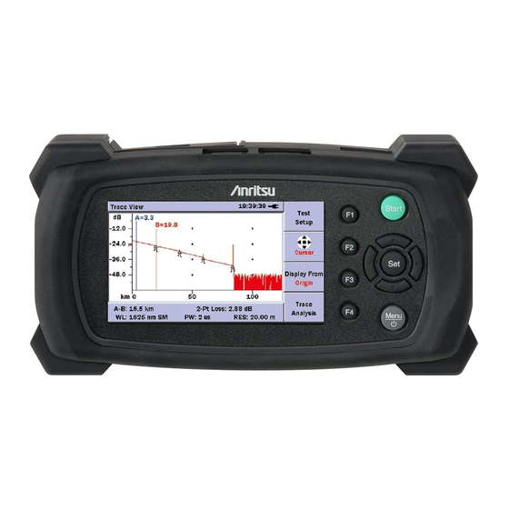
- Page 124 Trace View Screen The Trace View screen is accessed by pressing View Trace (F4) on the Fault Locate Step – Summary screen (see Figure 4-15 on page 4-18). Figure 4-20: Trace View screen 1 A to B Cursor distance 2 2-Point Loss (dB) measurement 3 Trace graph 4 Softkeys A to B Cursor Distance...
- Page 125 between the two points. Normally the Cursor A (Y-axis) data is greater than the Cursor B (Y-axis) data and a positive loss measurement is displayed. Otherwise, the loss value is reported as a negative quantity called a “gainer”. Trace Graph The Trace graph displays the trace data in graph form.
- Page 126 Trace Waveform The Trace Waveform (or Trace) is the downward sloping line going from left to right that connects the data points collected during a test. See item 3 in Figure 4-21 on page 4-27. Cursors The cursors (see Figure 4-21 on page 4-27) are two vertical lines that extend from the top to the bottom of the trace graph.
- Page 127 Softkeys The Fault Locate mode has four softkeys which are accessed via the F1 – F4 keys located to the right of the LCD screen (see Figure 2-1 on page 2-1). If the legend on a softkey is dimmed, that function is not available.
- Page 128 Trace View Softkeys Press F1 to start a Real Time test. The legend on the softkey changes to “Stop Real Time” while the test is running. Pressing “Stop Real Time” stops the current real time test and changes the legend on the softkey back to “Start Real Time”.
- Page 129 Display From Three Display From modes are available for viewing the trace graph (Display from: Origin, B, or A). • Press Display From (F3) to scroll through the three modes. The red legend on the softkey displays the current Display From mode. Display From Origin –...
- Page 130 Positioning the Active Cursor To position the active cursor: Select the desired cursor (see “Setting the Active Cursor” on page 4-31 for details). Toggle Display From (F3) to the desired mode, Display From B or Display From A, depending on the cursor selected in step 1.
- Page 131 Press the Right Arrow key. Each key press decreases the distance/division value of the horizontal axis (X-axis) by a factor of two. To zoom out: • Press the Down Arrow key. Each key press increases the dB/division value of the vertical axis (Y-axis) by a factor of two.
- Page 132 Fault Locate Test To run the Fault Locate test application: Connect the fiber to be tested to the measurement port (see “Connecting Fiber to the Measurement Port” on page 2-20 for details). Power up the unit. The unit performs a self-test and then launches the Fault Locate application.
- Page 133 Locate test, regardless of the Threshold level, if the incoming signal level is detected. • For 780 nm units, the OTDR Fault Locate test can be performed if the incoming signal level is detected (in service test). 4. Fault Locate Step – If the Connection Check Step is enabled on the Preferences Setup screen (see Figure 4-4 on page 4-5) a connection check is performed.
- Page 134 Figure 4-22: Summary screen Press the Set key to view the Event Description dialog for the currently highlighted item in the Event table. Press the Set key again to close the Event Description dialog. Press View Trace (F4) to view the trace, if desired (see Figure 4-23).
- Page 135 Connect the next fiber to be tested and press the Start key to continue. Real Time Testing Real Time test mode provides a quick “real-time” view of the initial trace information. In this mode, trace data is not continually averaged, but is stopped and restarted after each screen update.
- Page 136 To stop a Real Time test: • Press Stop Real Time (F1) to stop the current real time test. The legend on the softkey changes to Start Real Time and the real time test ends. Connection Check When the Enable Connection Check Step check box is selected, the unit performs a connection check at the start of the Fault Locate step, rating the connection as either GOOD, FAIR, or POOR.
- Page 137 Press Continue (F2) to proceed with the test. POOR – When the Connection Check is “POOR” the following screen appears. To correct a POOR connection: Press Stop (F1) to stop the test. Clean all of the optical connectors. Press the Start key to re-start the test. MT9090A/MU909011A Network Master User’s Guide 4-39...
- Page 138 Press the Start key to re-start the test. If the Connection Check remains POOR after following the steps in the preceding procedure, contact the Anritsu Technical Support Center at: Phone: 1-800-ANRITSU or 972-761-4600 (Canada, U.S., Latin and South America)...
- Page 139 For details on setting up the Auto Save function see pages 4-9 through 4-12. Saving Files Manually You can perform a manual file save when AutoSave is not enabled. See “Auto Save Setups” on page 4-9 for details on disabling AutoSave. To manually save files: At the completion of a test, press the Menu/Power key.
- Page 140 Follow steps 4a through 4e to rename the file. Or – Continue at step 5 if you are not renaming the file. Use the BKSP softkey (F2) to clear the entry in the filename field. Each press of the BKSP softkey moves the text cursor one character to the left, while deleting the character in that space.
- Page 141 Highlight the Device field and use the Left or Right Arrow key to toggle the desired selection: Internal or USB. The USB selection is only available when a USB device (such as a USB memory stick) is attached to the unit. Select the desired directory/folder in which to save the file and then press the Set key.
- Page 142 4-44 MT9090A/MU909011A Network Master User’s Guide...
- Page 143 Chapter 5: Video Inspection Probe (VIP) Option The Video Inspection Probe (VIP) option is used to inspect fiber optic terminations. Use the VIP to inspect installed connectors located inside hardware devices or on the “backside” of patch panels, eliminating the need to either disassemble hardware devices prior to inspection or access the backside of patch panels.
- Page 144 Note Note The Software CD contains the VIP Analysis software which is for PC use only. See the software’s help set for details on its use Video Inspection Probe (VIP) This small, lightweight probe measures 139.7 mm in length. It contains a long-life coaxial LED source and 8.46 mm CCD video camera.
- Page 145 FS-PT-FC FS-PT-ST FS-PT-SC FC tip ST tip SC tip Universal Tips The two universal tips are primarily used for inspecting patch cords. The 1.25 mm tip is compatible with 1.25 mm ferrules (as used in LC and MU type connector) while the 2.5 mm tip is compatible with 2.5 mm ferrules (as used in FC, ST, and SC style connectors).
- Page 146 Attaching a Probe Tip Use the following procedure to attach a probe tip to the VIP. To attach a Probe tip: Remove the dust cap (see item 1 in Figure 5-2 on page 5-2). Or – If a probe tip is already attached, loosen the front retaining nut (see item 2 in Figure 5-3) until it slides freely on the Barrel assembly (see item 3 in Figure 5-3).
- Page 147 Probe tip (FC style) Front retaining nut Key channel Figure 5-4: Attaching a Probe Tip Note Do not adjust the set screw. The 1.25 mm and 2.5 mm Universal probe tips do not have keys. Secure the probe tip in place with the front retaining nut (see item 2 in Figure 5-4).
- Page 148 To Attach a Probe tip with Optics: Loosen the rear retaining nut on the barrel assembly (see item 2 in Figure 5-6). Align the key channel on the probe tip with the key on the probe housing (see items 3 and 4 in Figure 5-6).
- Page 149 1. Video Inspection Probe Connector Retaining nut 4. USB converter USB connector Figure 5-7: VIP Connected to USB Converter Connecting the VIP to the Unit Use the following procedure to connect the VIP to the Network Master. To connect the VIP to the Unit: Open the cover for the USB (Type A) port on the unit.
- Page 150 If the unit was not powered up, continue at step 4. Figure 5-8: VIP Screen – Live Mode Press the Menu/Power key . The unit preforms a self-test during which the Anritsu splash screen briefly appears, followed by the Network Master splash screen. MT9090A/MU909011A Network Master User’s Guide...
- Page 151 Once the self-test is complete, one of the following initial test application screens appears depends on the Power Meter Step and Connection Check Step settings made on the Preferences Setup screen (see Figure 4-4 on page 4-5): Power Meter Step screen (see Figure 3-1 on page 3-2), Connection Check Step Screen (see Figure 3-2 on page 3-3) or the initial Fault Locate Step screen (see Figure 3-3 on...
- Page 152 Exiting VIP Mode To exit VIP mode: • Press Exit (F4) to close the VIP application. Or – • Disconnect the VIP USB connector from the USB (Type A) port. Working with VIP Image Files Saving VIP Images Images captured with the VIP can be saved as PNG files which can be recalled for viewing on the Network Master or further analyzed by using the VIP Analysis software on a PC.
- Page 153 Figure 5-9: Save VIP Image screen Select the desired directory/folder in which to save the file and then press the Set key. Continue at step 4, if you are not selecting a different directory/folder. Edit the filename, if desired. Or – Continue at step 7 to use the current filename.
- Page 154 deleted all or as much of the current name as desired. Use the Left/Right/Up/Down Arrow keys to highlight the desired letter in the character matrix. Press the Set key to add the highlighted letter to the name field. Note To access numbers and symbols, press Mode (F1): the first key press opens Number mode the second key press opens Symbol mode the third key press returns to Alphabet...
- Page 155 Note You must have a Video Inspection Probe attached to the unit in order to access the VIP application. Press Load (F3), the Load VIP Image screen appears. Figure 5-10: Load VIP Image screen Select the desired directory/folder from which to load the file and then press the Set key.
- Page 156 Mass Storage File Operations The mass storage file operations are can not be accessed while in VIP mode. See “Exiting VIP Mode” on page 5-10 for details. Once the VIP application is closed, the follow file operations are available via the Mass Storage – File Operation screen (see Figure 3-12 on page 3-19).
- Page 157 Always use the AC Charger/Adapter to power the unit when performing a firmware update. To update the firmware: Copy the BBM file, furnished by Anritsu, to a USB memory stick (conforming to USB 1.1). Connect the USB memory stick to the USB (Type A) port on the unit.
- Page 158 Figure 6-1: Initial Firmware Update Screen The text “Finding Update File” changes to “Extracting Update File.” When the update file is fully extracted, the Installing new Firmware screen appears (see Figure 6-2 on page 6-3). Note If there is more that one BBM file on the USB memory stick, the Choose Update File dialog is superimposed over the Initial Firmware Update screen.
- Page 159 Figure 6-2: Installing New Firmware Screen There are two check boxes on the Installing New Firmware screen: • Re-Install Controller – The unit compares the version number of the currently installed Controller to the version number of the Controller contained in the BBM update file.
- Page 160 • Format Drives During Installation – Select the Format Drives During Installation check box to automatically re-format any User drives set up on the unit. The following warning is displayed when you select the Format Drives During Installation check box: Warning -- This Update will Format All User Drives....
- Page 161 The installation is complete when the Finish screen appears (see Figure 6-4). Press the Set key to finish installation of the upgrade. Figure 6-4: Finish Screen MT9090A/MU909011A Network Master User’s Guide...
- Page 162 MT9090A/MU909011A Network Master User’s Guide...
- Page 163 Calibration This section describes how to check the performance of the unit and calibrate measurement values. Contact Anritsu or our sales dealer when specifications are determined not to have been satisfied based on the performance test described here. Make sure that you can provide the following details when requesting repairs.
- Page 164 Performance Test The following five items are tested to check the performance of the MU909011A Series. (Items 4 and 5 only apply for the units is equipped with the optional VFL and OPM.) • Optical wavelength • Pulse width • Dynamic range ...
- Page 165 Table 7-1: MU909011A/A1/A2/A3-050 to 062 Specifications Item Rated values Remarks Wavelength 1550 nm ±30 nm 25°C (MU909011A/A1/A2/A3-050/060) Except during charging battery. 780 nm ±20 nm (MU909011A/A1/A2/A3-052/062) Pulse Width <10 ns Dynamic Range 25°C >7 dB (S/N=1) * Average Time: 10 seconds Except during charging battery.
- Page 166 Table 7-3: Measuring instrument (recommended) and optical fiber required for performance test Test item OTDR Measurement instrument and cable Optical Spectrum Analyzer MS9710B Wavelength: 0.6~1.75 µm Level: -65~+20 dBm Programmable Optical Attenuator MN9610B Wavelength: 1.1~1.65 µm Attenuation: 60 dB Waveform Monitor...
- Page 167 Table 7-3: Measuring instrument (recommended) and optical fiber required for performance test (Continued) Test item OTDR Measurement instrument and cable Optical power meter ML9001+MA9001B+MA9411A Wavelength: 0.38~1.15 µm Level: -70~7 dBm Reference light source MT9810A / MU952501A 1550 nm, +10 dBm (CW) Optical power meter...
- Page 168 Wavelength Check that the center wavelength satisfies the specifications. Connect the devices as shown in the following figure. Optical Optical MU909011 Variable Attenuator Spectrum Analyzer Series Optical Optical Fiber Fiber Figure 7-1: Wavelength Test – Connection Diagram Test Procedure: Start a Real-time measurement. The laser signal Optical Output from the MU909011A series unit is received by the optical spectrum analyzer.
- Page 169 Pulse Width Check that the pulse width satisfies the specifications. Connect the devices as shown in the following figure. Optical Waveform Oscilloscope MU909011 Variable Attenuator Monitor Series Optical Optical Fiber Fiber Figure 7-2: Pulse Width Test – Connection Diagram Test Procedure: Start a Real-time measurement.
- Page 170 Dynamic Range (one-way back-scattered light dynamic range test) Check that the dynamic range satisfies the specifications. Connect the devices as shown in the following figure. MU909011 Series SM Optical Fiber (800 m) Far End: Grease for connection Figure 7-4: Dynamic Range Test – Connection Diagram Test Procedure: Start the measurement.
- Page 171 Optical Power Level and Wavelength of Visual Fault Locator (MU909011A1 / A3) Check that the output power level and wavelength of the optional Visual Fault Locator (the VFL is a Visible Laser Diode) satisfy their respective specifications. Note Note This test is performed only on units equipped with the optional Visual Fault Locator (VFL).
- Page 172 Test Procedure: Select the VFL and then set its output mode to CW. See “To use the Visual Fault Locator:” on page 3-7 for details. Measure the center wavelength using optical spectrum analyzer and the optical output power level using optical power meter respectively. Check that the output power level and wavelength of VFL satisfy their respective specifications.
- Page 173 Measurement Accuracy of the Optical Power Meter (MU909011A2 / A3) Check that the measurement accuracy of OPM (Optical Power Meter) satisfies the specification. Note Note This test is only performed on units equipped with the optional Optical Power Meter (OPM). Connect the devices as shown in the following figure.
- Page 174 Connect the optical variable attenuator and reference optical sensor. Adjust the level to -20.00 dBm using the variable attenuator. Connect the optical variable attenuator and MU909011 Series. Check the value of optical power meter is -20.0 ±0.5 dBm. 7-12 MT9090A/MU909011A Network Master User’s Guide...
- Page 175 Calibration The parameters that can be calibrated with the MU909011 Series are the Backscatter coefficient (BSC) level and the measurement accuracy of OPM (Optical Power Meter). Of these, the Backscatter coefficient level is the only parameter that the user can calibrate. Note Note Calibration of the measurement accuracy of the OPM...
- Page 176 Restart the measurement to confirm the return loss is equal to the R dB value. Optical Power Meter Calibration Please contact Anritsu for calibration of the OPM measurement accuracy. To maintain the performance of this parameter, we recommend that MU909011 Series units are calibrated once a year.
- Page 177 Performance Test Result Sheet Test site: Report No.; Date: Test supervisor: Equipment name: Serial No. (mainframe): Serial No. (module): Ambient temperature °C Relative humidity Note: MT9090A/MU909011A Network Master User’s Guide 7-15...
- Page 178 MU909011A/A1/A2/A3-050/060 Test item Rated Value Results Remarks 25°C, Wavelength 1550 nm 1550 nm±30 nm Except during charging battery. Pulse width <10 ns 25°C, Dynamic Average time: Range >7 dB 10 seconds (S/N=1) Except during charging battery. 1550 nm, CW -20 dBm...
- Page 179 MU909011A/A1/A2/A3-052/062 Test item Rated Value Results Remarks 25°C, Wavelength 780 nm 780 nm ±20 nm Except during charging battery. Pulse width <10 ns 25°C, Average time: Dynamic 10 seconds Range >7 dB Except during (S/N=1) charging battery. 1550 nm, CW -20 dBm...
- Page 180 7-18 MT9090A/MU909011A Network Master User’s Guide...
- Page 181 Chapter 8: Maintenance Daily Maintenance Be sure to turn off the power before performing daily maintenance. Panel surface dirt When the external surfaces become dirty, or when using the Network Master in dusty locations, etc., or before long-term storage, clean off any soiling using a soft cloth slightly moistened with neutral detergent.
- Page 182 Notes On Storage Remove any dust or dirt adhering to the equipment before storage. Remove batteries from the Network Master. Pack accessories, such as adapters and CD-ROM, etc., into the accessories box and store it with the main frame. Avoid storing in these places: •...
- Page 183 • Temperature: 5°C to 45°C • Humidity: 40% to 80% • Little temperature and humidity fluctuations within 1 day Transporting and Disposal This section describes the precautions to observe when transporting and disposing of the main frame at the end of its useful life.
- Page 184 Transporting In addition to preventing vibration as much as possible, transport under conditions meeting the storage conditions outlined above. Disposal When the main frame has reached the end of its useful life, dispose of it in accordance with local environmental regulations.
- Page 185 MT9090A/MU909011A Network Master User’s Guide...
- Page 186 MT9090A/MU909011A Network Master User’s Guide...
- Page 187 Appendix A: Specifications Table A-1: Specifications Item Specifications Remarks Model name, MT9090A Unit name Mainframe Model name, MU909011A Unit name Drop Cable Fault Locator Module MU909011A-052 780 nm, single mode, UPC MU909011A-062 780 nm, single mode, APC MU909011A1-052 780 nm, single mode, UPC, visible laser diode MU909011A1-062 780 nm, single mode, APC, visible laser diode MU909011A2-052 780 nm, single mode, UPC, power meter...
- Page 188 Table A-1 Specifications (Continued) Item Specifications Remarks Temperature 25°C 780 nm±20 nm (-052/062) (except during Wavelength 1550 nm±30 nm (-050/060) charging battery) 10/125 µm single mode fiber Fiber under test (ITU-T G.652) PC type: • FC option 037 Appending one ...
- Page 189 Table A-1 Specifications (Continued) Item Specifications Remarks Manual measurement Measurement item Loss and distance between cursor A and cursor B Real time Trace update time: 1 second or less measurement Distance Range 1 km to 10 km (IOR=1.500000) (Auto Setting, Option 050/060) 1 km to 2.5 km...
- Page 190 Table A-1 Specifications (Continued) Item Specifications Remarks Number of sampling 20001 points (1.0 km Distance Range) points 25001points (2.5 km Distance Range) Auto Setting 20001 points (10.0 km Distance Range) (Option 050/060) 1.3000 to 1.7000 (0.0001 step) -90.0 to -40.0 (0.1 step) Power Meter Fiber under test SM Optical fiber (ITU-T G.652)
- Page 191 Table A-1 Specifications (Continued) Item Specifications Remarks • Auto Backlight OFF: OFF, 5 to 60 min (5 min step) • Auto Power OFF: OFF, 30 to 120 min (30 min step) • Show internal launch fiber: Enable / Disable • Distance unit setting: Meters or Feet Other functions...
- Page 192 Table A-1 Specifications (Continued) Item Specifications Remarks • Dedicated battery pack or 4 AA Ni-MH batteries • DC: rating 9 V Power supply • AC: rating100 to 240 V, frequency: 50/60 Hz, (with dedicated AC adapter)* Power consumption 12 VA or less (including during charging battery) Back light Low Battery operating...
- Page 193 Table A-1 Specifications (Continued) Item Specifications Remarks Environmental conditions Operating – temperature 0 to +50°C 80% humidity No condensation Storage – temperature -20 to +60°C 80% humidity No condensation Vibration MIL-T-28800E Class3 Shock MIL-T-28800E Drop MIL-T-28800E Style C (20.3 cm corner, surface;...
- Page 194 Table A-2: Ni-MH Battery Pack Item Specifications Remarks Battery type Ni-MH Battery pack Voltage, Capacity DC 4.8 V, 2700 mAh Table A-3: AC Charger/Adapter Item Specifications Remarks AC rated input AC 100 to 240 V, 50 / 60 Hz * DC rated input 9 Vdc, 1.7 A Dimensions...
- Page 195 Table A-4: Parts and Accessories Item Specifications Model Name Optical adapter FC Type J0057 FC/PC patch cord (SM fiber) J0635x* Replaceable optical connector J0617B (FC-PC) Replaceable optical connector J0618D (ST) Replaceable optical connector J0618E (DIN) Replaceable optical connector J0619B (SC) Replaceable optical connector J0739A (FC-APC)
- Page 196 Table A-4: Parts and Accessories (Continued) Deluxe soft case B0602A Strap Z1023A Operation Manual CD version W2989AE Operation Manual Printed version W2988AE Connector Video Inspection OPTION-545VIP Probe (VIP option) Hard case for VIP option FS-PT-USB-CASE *: Use the following codes to specify the length (x) of the patch cord. A: 1 meter B: 2 meters C: 3 meters...
- Page 197 The MT9090A and MU909011A include the software shown in the table below. The software listed in the table is not covered under the Anritsu Software License Agreement. The details of each software license can be accessed from the following URL....
- Page 198 Package Name License Remarks (*5) portman 5 beta Other MT9090A/MU909011A Network Master User’s Guide...
- Page 199 Index xvii xvii equipment certificate viii battery fluid warning export management battery pack external storage media disposal procedure USB memory calibration seal IEC 61010 Standard caution symbol CE marking Class 1 Laser safety Laser radiation markings Class 3R Laser safety Laser radiation warning conformity markings Laser safety...
- Page 200 performance-guarantee seal warning symbol prohibited operation symbol warranty Out-of-warranty repairs WEEE directive Wheeled Bin symbol recycle symbols Repair warning repairs Return Materials Authorization RMA number safety precaution symbol safety symbols caution prohibited operation safety precaution warning Service and Sales offices symbols - safety technical support USB memory...
Need help?
Do you have a question about the Network Master Series and is the answer not in the manual?
Questions and answers