Table of Contents
Advertisement
Revised
October 2016
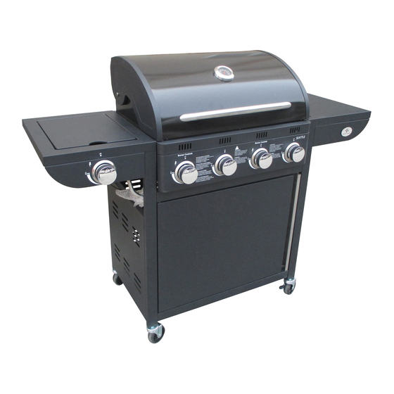
Assembly, use and maintenance
Gas Barbecue SEATTLE – GG301402B
!
NB: READ AND FOLLOW
THE INSTRUCTIONS ON LEAK
TESTING IN THE MANUAL
!
WARNING: Do not light the
grill before you have read the
LIGHTING INSTRUCTIONS in this
manual.
!
FAT FIRE:
• Shut off gas supply to the grill.
• Disconnect gas regulator.
• Open lid.
• Wait until the fire goes out.
Do not use water to extinguish the fire!
READ THIS MANUAL AND
FAMILIARIZE YOURSELF WITH
THE PRODUCT BEFORE USE
!
NB: Read the chapter on
MAINTENANCE AND CLEANING.
The guarantee can be invalid if
correct maintenance is not
performed.
Keep this manual for later
reference. It should follow the
owner of the product.
FOR OUTDOORS USE ONLY.
Advertisement
Table of Contents

Subscribe to Our Youtube Channel
Related Manuals for NORDIC SEASON SEATTLE


Summary of Contents for NORDIC SEASON SEATTLE
- Page 1 Assembly, use and maintenance Gas Barbecue SEATTLE – GG301402B READ THIS MANUAL AND NB: READ AND FOLLOW FAMILIARIZE YOURSELF WITH THE INSTRUCTIONS ON LEAK THE PRODUCT BEFORE USE TESTING IN THE MANUAL NB: Read the chapter on WARNING: Do not light the MAINTENANCE AND CLEANING.
-
Page 2: Table Of Contents
Table of contents Warnings ..... . 3 Technical data ....4 Gas Category . -
Page 3: Warnings
WARNINGS ! Failure to follow the instructions provided can imply a risk of serious injury to personnel and fixed installations. Some grill parts can be sharp, we recommend wearing gloves when assembling and lifting. Sharp edges can cause injury. The grill is intended for outdoor use only in well-ventilated areas. Never grill in enclosed spaces or under a roof, due to the danger of the lack of oxygen. -
Page 4: Technical Data
TECHNICAL DATA Total output: 15,22kW (Main burners 4 x 2,93 kW ) (Side burner 3,5 kW) Gas consumption: 1085 gram/time. (Main burners 835 gram/hour) (Side burner 250 gram/hour) Hose and regulator: Must be approved according to EN standard. Gas bottle (not included): Use standard bottle approved for use in the Nordic Region. -
Page 5: Parts Overview
PARTS OVERVIEW... -
Page 6: Parts List
PARTS LIST Item Part Qty. Item Part Qty. Lid and Body Assembly Casters (No Locking) Warming Rack Left Door Cooking Grid Back Board Flame Tamer Bottom Shelf Side Burner Grate Right Rear Support Leg Left Side Burner Assembly Right Side Table Left Rear Support Leg Right Front Support Leg Left Front Support Leg... -
Page 7: Assembly Instructions
ASSEMBLY INSTRUCTIONS PLEASE FOLLOW THESE INSTRUCTIONS STEP BY STEP. WE RECOMMEND TWO PEOPLE TO ASSEMBLE THE GRILL TO AVOID HEAVY LIFTING. Exercise caution when using electric tools – their strength can damage the screws. TOOLS FOR ASSEMBLY (not included): Medium size flat blade or Philips/cross-point screwdriver ... - Page 8 Fig 1 Fix the Cabinet Side Panel(10) on the Left Rear Support Leg (7) and Left Front Support Leg (8) using 4 pcs M6x12 (A) as Fig 1. Fig 2 Fix the Cabinet Side Panel (10) on the Right Rear Support Leg (15) and the Right Front Support Leg (17) using 4pcs M6x12(A) as Fig 2.
- Page 9 Fig 3 Fix Bottom Shelf (14) on Left Leg Assembly (7+8) and Right Leg Assembly (15+17) , using 4pcs M6x12 (A). Note: The direction of bottom shelf should be front direction assemble with front left/right leg. Fig 4 Fix Upper Leg Support Of Door(19) on front Left Leg (8) and Right front Leg (17) using 2pcs M6x12 (A) as Fig 4.
- Page 10 Fig 5 Fix 2pcs Casters (11) on Left Leg Assembly and 2pcs Casters (20) on Right Leg Assembly as Fig 5.. Fig 6 Fix shelf backboard(13) on Left Rear Support Leg (7) and Right Rear Support Leg (15) using 4pcs M6x12 (A) as Fig 6.
- Page 11 Fig 7a Fig 7b keeping approx keeping space approx 5mm space Fig 7c Fig 7d Fix Lid and Body Assembly(1) on Left Leg Assembly and Right Leg Assembly, using 8pcs M6x55(B). Do not tighten the M6x55 (B) as Fig 6c & 7d. Keep approx. 5mm space, for further easy assemble side burner kit and side table.
- Page 12 Fig 9 Fig 9 Fix Left Side Burner Assembly (6) on Left Leg Assembly as Fig 9a. Fix Right Side Table(16) on Right Leg Assembly(15) as Fig 9b. Fig 10 b Fig 10a Fasten Left Side Burner Assembly(6) and Right Side Table(16) on Body, using 4pcs M6x12(A) as Fig 10a &...
- Page 13 M4x8 Fig 11 Fig 11 Take out Side Burner Grate(5) from Side Burner as Fig 11a, and detach 2pcs M4x8 Combo Truss Head Bolts from bent pipe of Left Side Burner as Fig11b Left Side Burner Valve Straight view Straight view Fig 11 Fig 11...
- Page 14 Fig 11e Fasten 2 pcs M4x8 (detach from Fig11b) M4*8 Combo Truss Head Bolts on Left Side Burner as Fig 11e Enlarged Drawing Fig 11f Plug Ignition wire terminal into Left Side Burner Electrode as Fig 11f. Fig 11 ...
- Page 15 Fig 12 Firstly, fix left door(12) on the bottom shelf(14), then, carefully, press down the swing door shaft of upper leg support of door(19) as Fig 12. Fig 13 Fix 5 pcs knob (9) to each valve pole properly as Fig 13.
- Page 16 Fig 14 Fix 4 pcs knob (9) to each valve pole properly as Fig 14. Fig 15 Place the cooking grids (3) onto the body as Fig 15.
- Page 17 Fig 16 Place the warming rack(2) on body as Fig 16. Fig 17 Attach the oil cup(18) slide into the slot at the bottom of body as Fig 17.
- Page 18 Gas Hose Fig 18 Plug nippel(C) into the hose and fasten it by clip. Then fasten connector on the left side burner valve as Fig 18. Note: This grill does not include the hose as pic. Hose can be purchased in most stores selling gas.
-
Page 19: Connecting The Gas
CONNECTING THE GAS ALWAYS PERFORM A GAS LEAK TEST BEFORE USING THE GRILL (SEE SEPARATE CHAPTER). Regulator and hose: • Check the gas hose regularly for cracks, damage and decay. Never use a damaged gas hose. • Check that the movable plastic collar on the regulator is intact and that it has not been damaged by hot grill parts. -
Page 20: Leak Test
Important! Leak test. Before using the grill, perform a thorough leak test. Perform the same test each time the gas bottle, regulator or hose is changed and always when the grill has not been used for a while. • Prepare a mixture of two parts washing up liquid and one part water. •... -
Page 21: Lighting The Barbecue
LIGHTING INSTRUCTIONS Lighting the grill • Check that all controls are in the "OFF" position. • Open the gas tap on the regulator. • Open the lid (must always be open when lighting the grill). • Open the gas tap on the regulator and wait around 5 seconds. •... -
Page 22: Safety Instructions
SAFETY INSTRUCTIONS! 1. Always keep an eye on the grill when in use. Never allow children or others who require supervision near the grill when in use. 2. This grill is only intended for outdoor use and must not be used under a roof. Do not use under normal ground level. -
Page 23: Tips
TIPS 1. A clean grill works better, causes less smoke and prevents fat catching fire. Burn off the grill after use by opening the lid and burning all the burners at full power for 10 minutes. Allow the grill to cool, and then brush off ash from flame guards and grates. 2. -
Page 24: Maintenance
Maintenance: • Check that the burners are burning correctly regularly. • Remove the grill grate and flame guards. • Light the grill normally. • Turn the controls from low to high, check there is a difference in flame strength and that the flames are blue, not orange. -
Page 25: Troubleshooting
FEILSØKNING Problem Possible cause Solution Burners will not light when The electrode is covered with Clean the electrode. using the lighter. grease or food deposits. The wire to the electrode is loose. Secure the wire. Gas supply blocked. Check for blockages. Wire damaged. -
Page 26: Consumer Contact
CONSUMER CONTACT Nordic Season Products E-post: support@nordicseason.no www.nordicseason.no Always attach your receipt and product serial number when making a warranty claim. The serial number is on the silver-coloured sticker on the bottom shelf. Made in China for Nordic Season Products AS...
Need help?
Do you have a question about the SEATTLE and is the answer not in the manual?
Questions and answers