
Related Manuals for Peak IPEH-003026


Summary of Contents for Peak IPEH-003026
-
Page 1: User Manual
PCAN-PCI Express CAN Interface for PCI Express User Manual Document version 3.5.1 (2017-01-30) - Page 2 Copyright © 2017 PEAK-System Technik GmbH Duplication (copying, printing, or other forms) and the electronic distribution of this document is only allowed with explicit permission of PEAK-System Technik GmbH. PEAK-System Technik GmbH reserves the right to change technical data without prior announcement.
-
Page 3: Table Of Contents
PCAN-PCI Express – User Manual Contents Introduction Properties at a Glance System Requirements Scope of Supply Installing the Software and the Card Connecting the CAN Bus Connection over D-Sub connector 3.1.1 Slot Bracket with D-Sub Connectors Voltage Supply of External Devices Cabling 3.3.1 Termination... - Page 4 PCAN-PCI Express – User Manual Appendix B Dimension Drawing Appendix C Quick Reference...
-
Page 5: Introduction
PCAN-PCI Express – User Manual Introduction The PCAN-PCI Express card enables the connection of a PC with PCI Express slots to CAN networks. There is galvanic isolation of up to 500 Volts between the computer and CAN sides. The card is available as a single, dual, or four-channel version. -
Page 6: System Requirements
Windows. You can find device drivers for Linux and the corresponding application information on the provided DVD in the directory branch Develop and on our website under www.peak-system.com/linux. System Requirements A vacant PCI Express slot in the computer Operating system Windows 10, 8.1, 7 (32/64-bit) - Page 7 PCAN-PCI Express – User Manual Programming interfaces for standardized protocols from the automotive sector Manual in PDF format...
-
Page 8: Installing The Software And The Card
The navigation program starts. Select in the main menu Drivers and click on Install now. Confirm the message of the User Account Control related "Installer database of PEAK Drivers". The driver setup starts. Follow the program instructions. Do the following to install the card: Attention! Electrostatic discharge (ESD) can damage or destroy components on the card. - Page 9 Do the following to check the operational readiness: Open the Windows Start menu. Type peakcpl and press Enter . The information window for PEAK hardware appears. The plug-in card must be displayed in the table on the CAN Hardware tab.
-
Page 10: Connecting The Can Bus
PCAN-PCI Express – User Manual Connecting the CAN Bus Connection over D-Sub connector A High-speed CAN bus (ISO 11898-2) is connected to the 9-pin D-Sub connector. The pin assignment for CAN corresponds to the specification CiA® 303-1. Figure 1: Position of the sockets for the CAN connection, CAN 3 (upper left position), CAN 4 (upper right position) Figure 2: Pin assignment of High-speed CAN connection (view onto a male connector on the PCAN-PCI Express card) - Page 11 For more information see the next section 3.2. Tip: Connect a CAN bus with a different transmission standard via a bus converter. PEAK-System offers different bus converter modules like the PCAN-TJA1054 for a Low-speed CAN bus according to ISO 11898-3.
-
Page 12: Slot Bracket With D-Sub Connectors
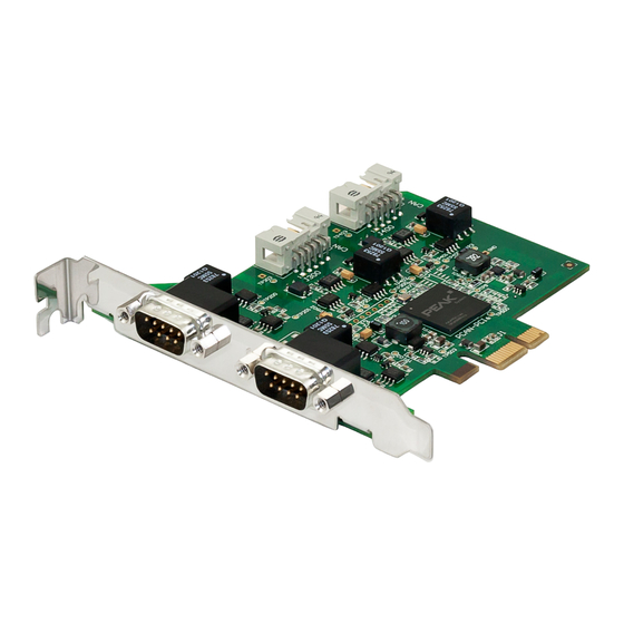
PCAN-PCI Express – User Manual 3.1.1 Slot Bracket with D-Sub Connectors Figure 4: Dual channel slot bracket Four-channel version only: To connect a CAN bus to the PCAN-PCI Express card, use the supplied slot bracket. After you have con- nected the cables from the slot bracket with the 10-pin sockets of CAN port 3 and 4, you can connect the CAN busses with the D-Sub sockets. -
Page 13: Voltage Supply Of External Devices
PCAN-PCI Express – User Manual Voltage Supply of External Devices External devices with low power consumption (e.g. bus converters) can be directly supplied via the CAN connector (independently for each connector on the dual or four-channel version). With a solder bridge per CAN channel on the PCAN-PCI Express board, a 5-Volt supply can optionally be routed to pin 1 of the D-Sub connector. - Page 14 PCAN-PCI Express – User Manual Figure 5: Position of the solder fields on the board’s bottom side for a 5-Volt supply at the CAN connection 5-Volt supply D-Sub connector Solder field Without With (Standard) (Pin 1) CAN 1 JP100 CAN 2 JP200 CAN 3 JP300...
-
Page 15: Cabling
PCAN-PCI Express – User Manual Cabling 3.3.1 Termination The High-speed CAN bus (ISO 11898-2) must be terminated with 120 ohms at both ends. The termination prevents interfering signal reflections and ensures the proper operation of the transceiver of the connected CAN nodes (CAN interface, control device). The PCAN-PCI Express card does not have an internal termination. -
Page 16: Maximum Bus Length
PCAN-PCI Express – User Manual 3.3.3 Maximum Bus Length High-speed CAN networks may have bit rates of up to 1 Mbit/s. The maximum bus length depends primarily on the bit rate. The following table shows the maximum possible CAN bus length at different bit rates: Bit rate Bus length... -
Page 17: Software And Api
PCAN-PCI Express – User Manual Software and API This chapter covers the provided software PCAN-View and the programming interface PCAN-Basic. Monitor Software PCAN-View PCAN-View is simple Windows software for viewing, transmitting, and logging CAN and CAN FD messages. Note: This chapter describes the use of PCAN-View with a CAN adapter. - Page 18 PCAN-PCI Express – User Manual Do the following to start and initialize PCAN-View: Open the Windows Start menu and select PCAN-View. The Connect dialog box appears. Figure 8: Selection of the hardware and parameters Select an interface from the list. From the drop-down list, select the Bit rate that is used by all nodes on the CAN bus.
-
Page 19: Receive/Transmit Tab
PCAN-PCI Express – User Manual 4.1.1 Receive/Transmit Tab Figure 9: Receive/Transmit Tab The Receive/Transmit tab is the main element of PCAN-View. It contains two lists, one for received messages and one for the transmit messages. The CAN data format is hexadecimal by default. Do the following to transmit a CAN message with PCAN-View: Select the menu command Transmit >... - Page 20 PCAN-PCI Express – User Manual Enter the ID, the data Length, and the CAN message Data. Note: With the program version 4 of PCAN-View, the DLC field was renamed to Length. Latter reflects the actual data length. Enter a value into the Cycle Time field to choose manually or periodically message transmission.
-
Page 21: Trace Tab
PCAN-PCI Express – User Manual 4.1.2 Trace Tab Figure 11: Trace Tab On the Trace tab, the data tracer (data logger) of PCAN-View is used for logging the communication on a CAN bus. During this process the messages are cached in the working memory of the PC. Afterwards they can be saved to a file. -
Page 22: Pcan-Pci Express Tab
PCAN-PCI Express – User Manual 4.1.3 PCAN-PCI Express Tab Figure 12: PCAN-PCI tab (example) The PCAN-PCI Express tab contains some detailed information about the hardware and driver. 4.1.4 Status Bar Figure 13: Display of the Status Bar The status bar shows information about the current CAN connection, about error counters (Overruns, QXmtFull) and shows error messages. -
Page 23: Linking Own Programs With Pcan-Basic
On the provided DVD, you can find files of the programming interface PCAN-Basic in the directory branch Develop. This API provides basic functions for linking own programs to CAN- and CAN FD interfaces by PEAK-System and can be used for the following operating systems: Windows 10, 8.1, 7 (32/64-bit) Windows CE 6.x (x86/ARMv4) -
Page 24: Features Of Pcan-Basic
Use of up to 16 channels for each hardware unit (depending on the PEAK CAN interface used) Simple switching between channels of a PEAK CAN interface Driver-internal buffer for 32,768 messages per CAN channel Precision of time stamps on received messages up to 1 μs (depending on the PEAK CAN interface used) Supports PEAK-System‘s trace formats version 1.1 and 2.0 (for... -
Page 25: Principle Description Of The Api
PCAN-PCI Express – User Manual Extended system for debugging operations Multilingual debugging output Output language depends on operating system Debugging information can be defined individually Thread-safe API Tip: An overview of the API functions is located in the header files. You can find detailed information about the PCAN-Basic API on the provided DVD in the text and help files (file name extensions .txt and .chm). -
Page 26: Notes About The License
Notes about the License Device drivers, the interface DLL, and further files needed for linking are property of the PEAK-System Technik GmbH and may be used only in connection with a hardware component purchased from PEAK-System or one of its partners. If a CAN hardware component... -
Page 27: Technical Specifications
PCAN-PCI Express – User Manual Technical Specifications Connectors Computer PCI Express x1 (1 Lane), Specification 1.1 D-Sub (m), 9 pins Pin assignment according to specification CiA® 303-1 Specification ISO 11898-2, High-speed CAN 2.0A (standard format) and 2.0B (extended format) Bit rates 5 kbit/s - 1 Mbit/s Controller FPGA implementation (SJA1000 compatible) - Page 28 PCAN-PCI Express – User Manual Environment Operating temperature -40 - +85 °C Temperature for storage -40 - +125 °C and transport Relative humidity 15 - 90 %, not condensing Directive 2014/30/EU DIN EN 55024:2016-05 DIN EN 55022:2011-12...
-
Page 29: Appendix Ace Certificate
PCAN-PCI Express – User Manual Appendix A CE Certificate... -
Page 30: Appendix B Dimension Drawing
PCAN-PCI Express – User Manual Appendix B Dimension Drawing Figure 15: Dimension drawing PCAN-PCI Express The figure does not show the actual size of the product. -
Page 31: Appendix C Quick Reference
Check the operational readiness. Open the Windows Start menu. Type peakcpl and press Enter . An information window for PEAK Hardware opens. The plug-in card must be displayed in the table on the CAN Hardware tab. Getting Started under Windows Run the CAN monitor PCAN-View from the Windows Start menu as a sample application for accessing the card.
Need help?
Do you have a question about the IPEH-003026 and is the answer not in the manual?
Questions and answers