Table of Contents
Advertisement
Quick Links
Advertisement
Table of Contents

Subscribe to Our Youtube Channel
Related Manuals for Peak USB to CAN Interface


Summary of Contents for Peak USB to CAN Interface
- Page 1 PCAN-USB USB to CAN Interface User Manual V2.1.4...
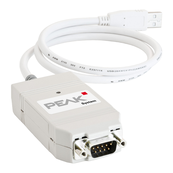
- Page 2 PCAN-USB – User Manual Products taken into account Product Name Model Part Number PCAN-USB IPEH-002021 PCAN-USB opto-decoupled Galvanic isolation for CAN IPEH-002022 interface The cover picture shows the product PCAN-USB opto-decoupled. CANopen® and CiA® are registered community trade marks of CAN in Automation e.V.
-
Page 3: Table Of Contents
PCAN-USB – User Manual Contents Introduction Properties at a Glance System Requirements Scope of Supply Installing the Software and the Adapter Connecting the CAN Bus D-Sub Connector Supplying External Devices via the CAN Connector Cabling 3.3.1 Termination 3.3.2 Example of a Connection 3.3.3 Maximum Bus Length Operation... - Page 4 PCAN-USB – User Manual Technical Specifications Appendix A CE Certificate Appendix B Dimension Drawings Appendix C Quick Reference...
-
Page 5: Introduction
PCAN-USB – User Manual Introduction The PCAN-USB adapter provides one CAN channel at computers with USB ports. Device drivers and programming interfaces exist for different operating systems, so programs can easily access a connected CAN bus. Tip: At the end of this manual (Appendix C) you can find a Quick Reference with brief information about the installation and operation of the PCAN-USB adapter. -
Page 6: System Requirements
PCAN-USB – User Manual Extended operating temperature range from -40 to 85 °C (-40 to 185 °F) Note: This manual describes the use of PCAN-USB adapter with Windows. You can find device drivers for Linux and the corresponding application information on the provided DVD in the directory branch Develop and on our website under www.peak-system.com/linux. -
Page 7: Scope Of Supply
PCAN-USB – User Manual Scope of Supply PCAN-USB in plastic casing Device drivers for Windows 8, 7, Vista, XP (32/64-bit) and Linux (32/64-bit) Device driver for Windows CE 6.x (x86 and ARMv4 processor support) PCAN-View CAN monitor for Windows 8, 7, Vista, XP (32/64-bit) PCAN-Basic programming interface consisting of an interface DLL, examples, and header files for all common programming languages... -
Page 8: Installing The Software And The Adapter
PCAN-USB – User Manual Installing the Software and the Adapter This chapter covers the software setup for the PCAN-USB adapter under Windows and the connection of the adapter to the computer. Setup the driver before connecting the PCAN-USB adapter to the computer for the first time. - Page 9 PCAN-USB – User Manual Do the following to connect the PCAN-USB adapter to the computer and complete the initialization: Note: Do not use a USB extension cable to connect the PCAN- USB adapter to the computer. The use of an extension cable does not comply with the USB specification and can lead to malfunction of the adapter.
-
Page 10: Connecting The Can Bus
PCAN-USB – User Manual Connecting the CAN Bus D-Sub Connector A High-speed CAN bus (ISO 11898-2) is connected to the 9-pin D Sub connector. The pin assignment for CAN corresponds to the specification CiA® 102. Figure 1: Pin assignment High-speed CAN (view onto connector of the PCAN-USB adapter) With the pins 1 and 9 devices with low power consumption (e.g. -
Page 11: Supplying External Devices Via The Can Connector
PCAN-USB – User Manual Supplying External Devices via the CAN Connector On the PCAN-USB board (casing opened) a 5-Volt supply can optionally be routed to pin 1 and/or pin 9 of the D-Sub connector (PCAN-USB opto-decoupled: pin 1 only). Thus devices with low power consumption (e.g. - Page 12 PCAN-USB – User Manual Figure 2: PCAN-USB board (IPEH-002021), solder field JP3 5-Volt supply → None Pin 1 Pin 9 Pin 1 + Pin 9 PCAN-USB, solder field Figure 3: Bottom side of the PCAN-USB opto-decoupled board (IPEH-002022), solder field R11 5-Volt supply →...
-
Page 13: Cabling
PCAN-USB – User Manual Attention! Risk of short circuit! If the option described in this section is activated, you may only connect or disconnect CAN cables or peripheral systems (e.g. external bus converters) to or from the PCAN-USB adapter while it is de-energized (the adapter is not connected to the computer). -
Page 14: Maximum Bus Length
PCAN-USB – User Manual 3.3.3 Maximum Bus Length High-Speed-CAN networks may have bit rates of up to 1 Mbit/s. The maximum bus length depends primarily on the bit rate. The following table shows the maximum possible CAN bus length at different bit rates: Bit rate Bus length 1 Mbit/s... -
Page 15: Operation
PCAN-USB – User Manual Operation Status LED The PCAN-USB adapter has a red status LED which can be in one of the following conditions: Status Meaning There's a connection to a driver of the operating system. Slow blinking A software application is connected to the adapter. Quick blinking Data is transmitted via the connected CAN bus. -
Page 16: Using The Software
PCAN-USB – User Manual Using the Software This chapter covers the provided software PCAN-View and the programming interface PCAN-Basic. CAN Monitor PCAN-View for Windows PCAN-View for Windows is a simple CAN monitor for viewing, transmitting, and logging CAN messages. Figure 5: PCAN-View for Windows Do the following to start and initialize PCAN-View: If PCAN-View is already installed on the hard disk, open the Windows Start menu, go to Programs >... - Page 17 PCAN-USB – User Manual If you haven't installed PCAN-View together with the device driver, you can start the program directly from the supplied DVD. In the navigation program (Intro.exe) go to English > Tools, and under PCAN-View for Windows select the link Start.
-
Page 18: Receive/Transmit Tab
PCAN-USB – User Manual 5.1.1 Receive/Transmit Tab Figure 7: Receive/Transmit tab The Receive/Transmit tab is the main element of PCAN-View. It contains two lists, one for received messages and one for the transmit messages. Representation of CAN data is in hexadecimal format. - Page 19 PCAN-USB – User Manual Figure 8: Dialog box new transmit message Enter the ID and the data for the new CAN message. The field Cycle Time indicates if the message shall be transmitted manually or periodically. If you want to transmit the message periodically, you must enter a value greater than 0.
-
Page 20: Trace Tab
PCAN-USB – User Manual 5.1.2 Trace Tab Figure 9: Trace tab On the Trace tab the data tracer of PCAN-View is used for logging the communication on a CAN bus. During this process the CAN messages are cached in the working memory of the PC. Afterwards they can be saved to a file. -
Page 21: Pcan-Usb Tab
PCAN-USB – User Manual 5.1.3 PCAN-USB Tab Figure 10: PCAN-USB tab With the PCAN-USB tab you can assign a device ID to the adapter. Then it can be clearly identified during operation of several PCAN- USB adapters on a single computer. Furthermore, the current firmware version of the connected adapter is displayed on the tab. -
Page 22: Linking Own Programs With Pcan-Basic
PCAN-USB – User Manual Linking Own Programs with PCAN-Basic Figure 12: PCAN-Basic On the provided DVD you can find files of the programming interface PCAN-Basic in the directory branch Develop. This API provides basic functions for linking own programs to CAN interfaces by PEAK-System and can be used for the following operating systems: Windows 8, 7, Vista, XP (32/64-bit) -
Page 23: Features Of Pcan-Basic
PCAN-USB – User Manual 5.2.1 Features of PCAN-Basic Supports Windows 8, 7, Vista, XP (32/64-bit) and Windows CE 6.x operating system Multiple PEAK-System applications and your own can be operated on a physical CAN channel at the same time Use of a single DLL for all supported hardware types Use of up to 8 channels for each hardware unit (depending on the PEAK CAN interface used) Simple switching between the channels of a PEAK CAN interface... -
Page 24: Principle Description Of The Api
PCAN-USB – User Manual 5.2.2 Principle Description of the API The PCAN-Basic API is the interface between the user application and device driver. In Windows operating systems this is a DLL (Dynamic Link Library). The sequence of accessing the CAN interface is divided into three phases: 1. -
Page 25: Notes About The License
PCAN-USB – User Manual Completion To end the communication the function is called in CAN_Uninitialize order to release the reserved resources for the CAN channel, among others. In addition the CAN channel is marked as "Free" and is available to other applications. 5.2.3 Notes about the License Device drivers, the interface DLL, and further files needed for linking... -
Page 26: Technical Specifications
PCAN-USB – User Manual Technical Specifications Connectors Computer USB plug type A D-Sub (m), 9 pins Pin assignment according to specification CiA® 102 Type USB 1.1, compatible with USB 2.0 Specification ISO 11898-2, High-speed CAN 2.0A (standard format) and 2.0B (extended format) Bit rates 5 kbit/s - 1 Mbit/s Controller... - Page 27 PCAN-USB – User Manual Environment Operating temperature -40 - 85 °C (-40 - 185 °F) Temperature for storage -40 - 100 °C (-40 - 212 °F) and transport Relative humidity 15 – 90 %, not condensing EN 55024: 2011-09 EN 55022: 2011-12 EC directive 2004/108/EG Ingress protection IP20...
-
Page 28: Appendix A Ce Certificate
PCAN-USB – User Manual Appendix A CE Certificate... -
Page 29: Appendix B Dimension Drawings
PCAN-USB – User Manual Appendix B Dimension Drawings Figure 13: View PCAN-USB Figure 14: View PCAN-USB opto-decoupled The figures don't show the actual size of the product. -
Page 30: Appendix C Quick Reference
PCAN-USB – User Manual Appendix C Quick Reference Software/Hardware Installation under Windows Before connecting the PCAN-USB adapter to the computer set up the corresponding software package from the supplied DVD (with administrator privileges). Afterwards connect the PCAN-USB adapter to a USB port at your computer. The adapter is recognized by Windows and the driver is initialized.
Need help?
Do you have a question about the USB to CAN Interface and is the answer not in the manual?
Questions and answers