
Subscribe to Our Youtube Channel
Related Manuals for Airwell HA 34 RC


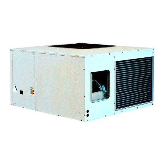
Summary of Contents for Airwell HA 34 RC
- Page 1 FROM EMAILAIR Industrial Range Roof Top Units HEATPUMP R 22 HA 34 RC HA 45 RC HA 52 RC HA 61 RC HA 75 RC HA 89 RC HA 110 RC INSTALLATION INSTRUCTIONS TH 3886 - B 3990132...
-
Page 2: General Recommendations
GENERAL RECOMMENDATIONS Congratulations for having selected an AIRWELL air conditioner. SAFETY DIRECTIONS Follow the safety rules in force when you are working on your appliance. Installation and maintenance of the equipment must only be performed by qualified specialists in accordance with the rules of good workmanship and prevailing stan- dards and instructions. -
Page 3: Declaration Of Conformity
EEC directives listed hereafter and with the nationnal legisl- gislation into wich these directives have been transposed. HA 34 RC / 45RC / 52RC / HA 61RC HA 75 RC / HA 89 RC / HA 110 RC... -
Page 4: Cooling Specifications
Roof Top Units HA / 34 /45 /52 /61 / 75 / 89 / 110 RC Roof Top Unit CONTENTS OF PARCEL 1 HA package units 1 bag with reference material RECEIVING UNIT Upon receipt, the unit should be carefully examined for any damage which may have occurred in transit, and such damage should be noted on the carrier’s delivery documents. -
Page 5: Warning / Caution
Roof Top Units HA / 34 /45 /52 /61 / 75 / 89 / 110 RC Roof Top Unit CONTENTS OF PARCEL R 22 ² R 22 ² R 22 l a t ² WARNING / CAUTION * These values are given for guidance. They must be checked and adjusted according to prevailing standards. -
Page 6: Net Weight
Roof Top Units HA / 34 /45 /52 /61 / 75 / 89 / 110 RC Roof Top Unit HANDLING NET WEIGHT Modell HA 34 HA 45 HA 52 HA 61 HA 75 HA 89 HA110 Heatpump 140 Kg 200 Kg 210 Kg 216 Kg 265 Kg 305 Kg 310 Kg Fork direction on fork lift truck... -
Page 7: Locating The Unit
Roof Top Units HA / 34 /45 /52 /61 / 75 / 89 / 110 RC Roof Top Unit LOCATING THE UNIT This series of packaged air conditioning units is designed for outdoor, rooftop or ground level installation. The unit must be installed on a firm level foundation, of adequate strength to support its full operating weight. Some form of vibration isolation such as rubber waffle pads should be installed between the unit and the supporting structure. - Page 8 Roof Top Units HA / 34 /45 /52 /61 / 75 / 89 / 110 RC Roof Top Unit DIMENSIONS HA 34 25.4 O.D copper drain 25.4 0.D DRAIN 1090 25 duct flanges 1120 mounting centres DIMENSIONS HA 45 - 52 25.4 O.D copper drain 25.4 0.D DRAIN 1320...
- Page 9 Roof Top Units HA / 34 /45 /52 /61 / 75 / 89 / 110 RC Roof Top Unit DIMENSIONS HA 61 - 75 25.4 O.D copper drain 25.4 0.D DRAIN 1320 25 duct flanges 1282 mounting centres DIMENSIONS HA 89 -110 25.4 O.D Copper drain 25.4 0.D DRAIN...
-
Page 10: Condensate Drain Line
Roof Top Units HA / 34 /45 /52 /61 / 75 / 89 / 110 RC Roof Top Unit CONDENSATE DRAIN LINE - Raise the appliance to provide traps on the condensate drain lines - Drain port: dia. 1" CAUTION: Never braze the condensate drain pipe to the appliance outlet fittings. -
Page 11: Installation
Any modifications carried out without the approval of Airwell may void the unit warranty. Mains supply cables must be sized to ensure adequate voltage at the unit terminals when the unit is starting and during full load operation. -
Page 12: Operating Units
Roof Top Units HA / 34 /45 /52 /61 / 75 / 89 / 110 RC Roof Top Unit WARNING WARNINGG BEFORE CARRYING OUT ANY WORK ON THE EQUIPMENT, MAKE SURE THAT THE ELECTRICAL POWER SUPPLY IS DISCONNECTED AND THAT THERE IS NO POSSIBILITY OF THE UNIT BEING STARTED INADVERTENTLY. - Page 13 Roof Top Units HA / 34 /45 /52 /61 / 75 / 89 / 110 RC Roof Top Unit COMMISSIONING (CONTINUED) Fan Drive. Pulley adjustment correct for expected air quantity and static pressure. (ii) Belt tension correct. Check that the Biloc Sheaves on both the fan shaft and the motor are correctly fitted to the bush and rotate without wobble.
-
Page 14: Maintenance
Roof Top Units HA / 34 /45 /52 /61 / 75 / 89 / 110 RC Roof Top Unit COMMISSIONING ( CONTINUED) ELECTRICAL 3.1 Set Points (a) Set point of compressor overload relay. (b) Set point of indoor fan motor overload relay. NOTE: The outdoor fan motor is fitted with an internal automatic reset overload device. - Page 15 Roof Top Units HA / 34 /45 /52 /61 / 75 / 89 / 110 RC Roof Top Unit MAINTENANCE (CONTINUED) MAINTENANCE CHECKLIST 7.1 Enclosure Clean down external panels. Remove panels. Check insulation for damage or deterioration and repair as necessary. 7.2 Drain Pan Check drain ports and piping are clear.
-
Page 16: Power Circuit
Roof Top Units HA / 34 /45 /52 /61 / 75 / 89 / 110 RC Roof Top Unit ‘ PACKAGED ROOFTOPUNITS ‘ PACKAGED AIR CONDITIONERS MODELS HA 34 - 45 - 52 - 61 - 75 - 89 - 110 1 2 3 4 5 6 7 8 9 0 1 2 3 4 5 6 7 8 9 0 1 2 3 N 716 1 2 3 4 5 6 7 8 9 0 1 2 3 4 5 6 7 8 9 0 1 2 3... -
Page 17: Colour Code
Roof Top Units HA / 34 /45 /52 /61 / 75 / 89 / 110 RC Roof Top Unit 2.2) FAN MOTORS & RELATED EQUIPEMENT MO1 : outdoor air fan motor (see table 4) CO1 : capacitor of motor MO1 (see table 4) FO1 : contact of thermal relay of motor MO1 : contactor of indoor air fan motor (for HA 34, this is a relay) : indoor fan motor (see table 5 for HA 34) - Page 18 Roof Top Units HA / 34 /45 /52 /61 / 75 / 89 / 110 RC Roof Top Unit WIRING DIAGRAM : SE 3038A HA 34 C/RC...
- Page 19 Roof Top Units HA / 34 /45 /52 /61 / 75 / 89 / 110 RC Roof Top Unit WIRING DIAGRAM : SE 3039B HA 45 - 52 - 61 - 75 C/RC > > > > T1PRI T1SEC < >...
- Page 20 Roof Top Units HA / 34 /45 /52 /61 / 75 / 89 / 110 RC Roof Top Unit WIRING DIAGRAM : SE 3041B HA 89 - 110 C/RC...
- Page 21 Roof Top Units HA / 34 /45 /52 /61 / 75 / 89 / 110 RC Roof Top Unit WIRING DIAGRAM : 3117A HA 89 - 110 C/RC CONTROL > > > > T1PRI T1SEC < >...
- Page 22 Roof Top Units HA / 34 /45 /52 /61 / 75 / 89 / 110 RC Roof Top Unit CONTROLS CAC CONTROLLER Other voltage free contact control types including BMS single stage units with CAC CONTROLLER THERMOSTAT CAC PCB OR CONTROLLER TERMINAL NUMBERS 24 V C - 24 Volt NEUTRAL...
- Page 23 Roof Top Units HA / 34 /45 /52 /61 / 75 / 89 / 110 RC Roof Top Unit ı U BMS CONTROLLER RS485 12 V CAC PCB TERMINAL NUMBERS 12 V ALARM ON/OFF NOTES 3. An “RT” or “Cont” alarm may appear in initial 1.
- Page 24 Roof Top Units HA / 34 /45 /52 /61 / 75 / 89 / 110 RC Roof Top Unit ı U BMS CONTROLLER RS485 12 V CAC PCB TERMINAL NUMBERS 12 V OPTIONAL FAULT STATUS INDICATION 24 V ALARM FAN AUX CONTACTOR OPTIONAL RUN STATUS INDICATION 24 V XB 01035...
- Page 25 Roof Top Units HA / 34 /45 /52 /61 / 75 / 89 / 110 RC Roof Top Unit ı U BMS CONTROLLER RS485 12 V CAC PCB TERMINAL NUMBERS TO OTHER 12 V UNITS OPTIONAL FAULT STATUS INDICATION 24 V ALARM FAN AUX CONTACTOR OPTIONAL RUN STATUS...
- Page 26 Roof Top Units HA / 34 /45 /52 /61 / 75 / 89 / 110 RC Roof Top Unit U BMS CONTROLLER MASTER RS485 12 V CAC PCB TERMINAL NUMBERS TO OTHER 12 V UNITS Master U BMS CONTROLLER LOCAL RS485 12 V Local...
-
Page 27: Service / Warranty
Newcastle NSW 2300 NEW ZEALAND FAX: (09) 820 0332 TEL: (09) 920 0333 517A Rosebank Road Avondale, Auckland NZ www.airwell.com.au © Copyright 2003 WITH A CONCERN FOR A CONSTANT IMPROVEMENT , OUR PRODUCTS CAN BE MODIFIED WITHOUT NOTICE. PHOTOS NON CONTRACTUAL.
Need help?
Do you have a question about the HA 34 RC and is the answer not in the manual?
Questions and answers