
Related Manuals for Airwell HAF 18


Summary of Contents for Airwell HAF 18
-
Page 1: Service Manual
Service Manual HAF Series Indoor Units Outdoor Units HAF 18 YAF018 HAF 24 GCN 24 REFRIGERANT COOLING ONLY R410A HEAT PUMP FEBRUARY - 2010 SM HAFRPM 2-A.1 GB CONTENTS... - Page 2 LIST OF EFFECTIVE PAGES LIST OF EFFECTIVE PAGES Note: Changes in the pages are indicated by a “Revision#” in the footer of each effected page (when none indicates no changes in the relevant page). All pages in the following list represent effected/ non effected pages divided by chapters.
-
Page 3: Table Of Contents
TABLE OF CONTENTS Table of Contents INTRODUCTION ....................1-1 PRODUCT DATA SHEET ..................2-1 RATING CONDITIONS ..................3-1 OUTLINE DIMENSIONS ..................4-1 PERFORMANCE DATA & PRESSURE CURVES ..........5-1 SOUND LEVEL CHARACTERISTICS ..............6-1 ELECTRICAL DATA ....................7-1 WIRING DIAGRAMS .....................8-1 ELECTRICAL CONNECTIONS ................9-1 10. REFRIGERATION DIAGRAMS ................10-1 11. -
Page 4: Main Features
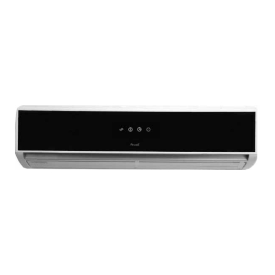
The new HAF series is split wall mounted type indoor unit. It has innovative flat design with background display. The models as below: HAF 18 HAF 24 Main Features The HAF series benefits from the most advanced technological innovations, namely: ●... -
Page 5: Outdoor Unit
For further details please refer to the Installation Manual, Appendix A. Accessories Remote Control Inbox Documentation Each unit is supplied with its own installation and operation manuals. Matching Table INDOOR UNIT OUTDOOR UNITS HAF 18 HAF 24 OUTLINE MODEL REFRIGER. √ YAF018 R410A √... - Page 6 PRODUCT DATA SHEET PRODUCT DATA SHEET HAF 18 | YAF018 HAF 18 Model Indoor Unit YAF018 Model Outdoor Unit Installation Method of Pipe Flared Characteristics Units Cooling Only Cooling Heating Btu/hr 17880 17880 18080 Capacity 5.24 5.24 5.30 1.63 1.63 1.46...
- Page 7 PRODUCT DATA SHEET HAF 24 | GCN 24 HAF 24 Model Indoor Unit GCN 24 Model Outdoor Unit Installation Method of Pipe Flared Characteristics Units Cooling Only Cooling Heating Btu/hr 23100 23100 22840 Capacity 6.77 6.77 6.70 2.12 2.12 2.09 Power input 3.20 3.20...
-
Page 8: Rating Conditions
RATING CONDITIONS RATING CONDITIONS Standard conditions in accordance with ISO 5151, ISO 13253 (for ducted units) and EN 14511. Cooling: Indoor: C DB 19 C WB Outdoor: 35 C DB Heating: Indoor: C DB Outdoor: 7 C DB 6 C WB Operating Limits 3.1.1 R410A Indoor... -
Page 9: Outline Dimensions
OUTLINE DIMENSIONS OUTLINE DIMENSIONS Indoor Unit: HAF 18, HAF 24 Outdoor Unit: YAF018 SM HAFRPM 2-A.1 GB CONTENTS... -
Page 10: Outline Dimensions
OUTLINE DIMENSIONS Outdoor Unit: GCN 24 SM HAFRPM 2-A.1 GB CONTENTS... -
Page 11: Operating Limits
PERFORMANCE DATA & PRESSURE CURVES PERFORMANCE DATA & PRESSURE CURVES HAF 18 / YAF018 5.1.1 Cooling Mode at 7.5m Tubing Connection. 230V : Indoor Fan at High Speed. ENTERING AIR WB/DB ID Coil( ENTERING AIR Data DB OD Coil( 15/21... - Page 12 PERFORMANCE DATA & PRESSURE CURVES 5.1.2 Heating ENTERING AIR DB ID COIL( ENTERING WB OD COIL( 2.78 1.17 2.68 1.24 2.57 1.31 2.99 1.20 2.89 1.26 2.78 1.33 3.18 1.21 3.07 1.28 2.97 1.36 3.87 1.27 3.71 1.35 3.55 1.43 5.30 1.46 5.46...
- Page 13 PERFORMANCE DATA & PRESSURE CURVES Model: HAF 18 / YAF018 5.2.1 Cooling SM HAFRPM 2-A.1 GB CONTENTS...
- Page 14 PERFORMANCE DATA & PRESSURE CURVES 5.2.2 Heating SM HAFRPM 2-A.1 GB CONTENTS...
- Page 15 PERFORMANCE DATA & PRESSURE CURVES PRESSURE CURVES 5.3.1 Model: HAF 18 / YAF018 =>Cooling Discharge Pressure VS.Outdoor Temp 40.0 30.0 20.0 10.0 Outdoor Temp.( C DB) Suction Pressure VS.Outdoor Temp 11.0 Outdoor Temp.( C DB) SM HAFRPM 2-A.1 GB CONTENTS...
- Page 16 PERFORMANCE DATA & PRESSURE CURVES 5.3.2 Model: HAF 18 / YAF018 =>Heating Discharge Pressure VS.Outdoor Temp 40.0 30.0 20.0 10.0 Outdoor Temp.( C WB) Suction Pressure VS.Outdoor Temp 10.0 Outdoor Temp.( C WB) SM HAFRPM 2-A.1 GB CONTENTS...
- Page 17 PERFORMANCE DATA & PRESSURE CURVES HAF 24 / GCN 24 5.4.1 Cooling Mode at 7.5m Tubing Connection. 230V : Indoor Fan at High Speed. ENTERING AIR WB/DB ID Coil( ENTERING AIR Data DB OD Coil( 15/21 17/24 19/27 21/29 23/32 7.14 7.39 7.57...
- Page 18 PERFORMANCE DATA & PRESSURE CURVES 5.4.2 Heating ENTERING AIR DB ID COIL( ENTERING WB OD COIL( 3.52 1.67 3.38 1.78 3.25 1.87 3.79 1.71 3.65 1.81 3.52 1.91 4.02 1.73 3.89 1.84 3.75 1.94 4.69 1.93 4.89 1.82 4.49 2.05 6.90 1.95 6.70...
- Page 19 PERFORMANCE DATA & PRESSURE CURVES Model: HAF 24 / GCN 24 5.5.1 Cooling SM HAFRPM 2-A.1 GB CONTENTS...
- Page 20 PERFORMANCE DATA & PRESSURE CURVES 5.5.2 Heating 5-10 SM HAFRPM 2-A.1 GB CONTENTS...
- Page 21 PERFORMANCE DATA & PRESSURE CURVES PRESSURE CURVES 5.6.1 Model: HAF 24 / GCN 24 =>Cooling Discharge Pressure VS.Outdoor Temp 40.0 30.0 20.0 10.0 Outdoor Temp.( C DB) Suction Pressure VS.Outdoor Temp 11.0 Outdoor Temp.( C DB) SM HAFRPM 2-A.1 GB 5-11 CONTENTS...
- Page 22 PERFORMANCE DATA & PRESSURE CURVES 5.6.2 Model: HAF 24 / GCN 24 =>Heating Discharge Pressure VS.Outdoor Temp 40.0 30.0 20.0 10.0 Outdoor Temp.( C WB) Suction Pressure VS.Outdoor Temp 10.0 Outdoor Temp.( C WB) 5-12 SM HAFRPM 2-A.1 GB CONTENTS...
-
Page 23: Sound Level Characteristics
SOUND LEVEL CHARACTERISTICS Sound Pressure Level Unit Wall 0.8m Mic. Figure 1 Soud Pressure Level Spectrum ( Measured as Figure 1 HAF 18 HAF 24 Noise spectrum & NC Curves Noise spectrum & NC Curves NC65 NC65 NC60 NC60 NC55... -
Page 24: Outdoor Units
SOUND LEVEL CHARACTERISTICS Outdoor units Unit Mic. Ground Figure 2 Sound Pressure Level Spectrum ( Measured as Figure 2 YAF 018 Cooling YAF 018 Heating GCN 24 Cooling GCN 24 Heating SM HAFRPM 2-A.1 GB CONTENTS... -
Page 25: Electrical Data
ELECTRICAL DATA ELECTRICAL DATA Single Phase Units MODEL HAF 18 HAF 24 from indoor from outdoor from indoor from outdoor Power Supply 1PH-230V-50Hz 1PH-230V-50Hz Max Current, A Circuit Breaker,A Power Supply Wiring No. X 3x1.5 mm 3x2.5 mm Cross Section mm 5x1.5 mm... -
Page 26: Wiring Diagrams
WIRING DIAGRAMS WIRING DIAGRAMS Indoor Unit: HAF 18, HAF 24 Outdoor Unit: YAF 018 SM HAFRPM 2-A.1 GB CONTENTS... - Page 27 WIRING DIAGRAMS Outdoor Unit: GCN 24 HEAT ATTENTION ! FOR INDOOR UNIT ELECTRICAL WIRING CAT N°: 433782 REV. 04 REFER TO INDOOR UNIT DIAGRAM SM HAFRPM 2-A.1 GB CONTENTS...
-
Page 28: Electrical Connections
ELECTRICAL CONNECTIONS ELECTRICAL CONNECTIONS HAF 18, HAF 24 SM HAFRPM 2-A.1 GB CONTENTS... -
Page 29: Refrigeration Diagrams
REFRIGERATION DIAGRAMS REFRIGERATION DIAGRAMS 10.1 Heat Pump Models 10.1.1 HAF 18, HAF 24 OUTDOOR UNIT INDOOR UNIT Service port Sensor Sensor Flared Valves connection Reverse valve Capillary tube Capillary Indoor coil tube Strainer Check Outdoor coil valve COOLING MODE OUTDOOR UNIT... - Page 30 REFRIGERATION DIAGRAMS 10.2 Cooling Only Models 10.2.1 HAF 18, HAF 24 OUTDOOR UNIT INDOOR UNIT Service port Sensor Flared Valves connection Capillary Indoor coil tube Strainer Outdoor coil 10-2 Service Manual - ALPHA CONTENTS...
-
Page 31: Tubing Connections
TUBING CONNECTIONS TUBING CONNECTIONS TUBE (Inch) ¼” ⅜” ½” ⅝” ¾” TORQUE (Nm) Flare Nuts 11-13 40-45 60-65 70-75 80-85 Valve Cap 13-20 13-20 18-25 18-25 40-50 Service Port Cap 11-13 11-13 11-13 11-13 11-13 Valve Protection Cap-end Refrigerant Valve Port (use Allen wrench to open/close) Valve Protection Cap Refrigerant Valve Service Port Cap... -
Page 32: Introduction
CONTROL SYSTEM CONTROL SYSTEM 12.1 Electronic Control 12.1.1 Introduction The electronic control information is designed for service application, and is common to the following groups of air-conditioners: ST/RC Group -Cooling only/ cooling and heating by heat pump SH Group -Cooling and heating by heat pump and supplementary heater. RH Group -Cooling, heating by heaters only. - Page 33 CONTROL SYSTEM 12.2 LEGEND 12.2.1 Abbreviations -Alternate Current - Air-Conditioner - ON or OFF status CLOCK - ON/OFF Operation Input, (dry contact) COMP - Compressor - Central Processing Unit ELUM - Extended Louver Upward Movement (Software Jumper) E²PROM, EEP - Erase Enable Programmable Read Only Memory - Heating Element - High Pressure Control - Hardware...
- Page 34 CONTROL SYSTEM - Software TEMP - Temperature - Without -The difference between SPT and RT. In Heat Mode: T=SPT-RT In Cool/Dry/Fan Mode: T= RT –SPT 12.2.2 List of A/C Groups The following table defines the different A/C groups, and the applicable operation modes for each group.
- Page 35 CONTROL SYSTEM 12.3 GENERAL FUNCTIONS FOR ALL MODELS 12.3.1 COMP operation For each Mode including POWER OFF & SB, a Min time delay of 3 min before COMP restarting, excluding DEICING Mode The Min operation time of COMP under different operating conditions is Min operation time of Operation Mode COMP...
- Page 36 CONTROL SYSTEM 12.3.3 OFAN operation Min time interval between OFAN ON/OFF state change is 30 sec. In general, OFAN starts together with COMP. 12.3.4 HE operation Minimum Heaters ON or OFF time is 30 sec. Heaters can be activated only if IFAN is on. In RH group, HE-1 and HE-2 will be activated only when COMP is operating, except in Dry Mode.
- Page 37 CONTROL SYSTEM (ii) The ICT and OCT no-change error can be disabled together by connecting a 4.7 k or 3.9 k ohm resistor (5%) to the OCT connector. These resistors are equivalent to a thermistor at 43+/-1 c and 48+/-1 c respectively.
-
Page 38: Cooling Mode
CONTROL SYSTEM Recover from the thermistor faults ICT/OCT/RAT is disconnected or shorted – The fault status will be cleared automatically when the connection is back to normal. ICT/OCT reading doesn’t change - The ICT no-change error is cleared automatically if a 3 c change in ICT is detected afterward. - Page 39 CONTROL SYSTEM 12.4.2 Cooling Mode: Cool, Auto (at Cooling) Temp: Selected desired temperature. Fan: HIGH, MED, LOW Timer: Any I Feel: On or Off Control function Maintains room temp at desired level by comparing RT and SPT. (RT - SPT) [ COMP OFAN USER FAN SPEED...
- Page 40 CONTROL SYSTEM 12.4.3 Cooling with Autofan Mode: Cool, Auto (at cooling) Temp: Selected desired temperature Fan: Auto Timer: Any I Feel: On or Off Control function Maintains room temp at desired level and controls the IFAN speed for opt comfort. (RT - SPT) [ COMP OFAN...
-
Page 41: Heating Mode
CONTROL SYSTEM 12.5 HEATING MODE 12.5.1 Heating Mode – General In heating Mode, temp. compensation schedule will be activated for wall mounted, ducted models, and ceiling mounted (i.e. NKN, CN, and NFC) according to the following table: Add to SPT SPT [ I-FEEL ON I-FEEL OFF... - Page 42 CONTROL SYSTEM In other models IFAN will operate in low speed for 30 sec and then stop. If COMP is OFF for more than 3 minutes and IFEEL Mode is inactive, IFAN will operate in low speed according to the following graph: IFAN (Low Speed) In RH group, IFAN starts when HE starts.
- Page 43 CONTROL SYSTEM 12.5.2 Heating, RC or SH Group Mode: Heat, Auto (at heating) Temp: Selected desired temperature Fan: HIGH, MED, LOW Timer: Any I Feel: On or Off Control function Maintains room temp. at desired level by comparing RAT or RCT to SPT. (RT - SPT) [ COMP (WVL)
- Page 44 CONTROL SYSTEM 12.5.3 Heating, RC or SH Group with Autofan Mode: Heat, Auto (at heating) Temp: Selected desired temperature Fan: Auto Timer: Any I Feel: On or Off Control function Maintains room temp at desired level by controlling COMP, IFAN and OFAN. (RT - SPT) [ COMP IFAN...
- Page 45 CONTROL SYSTEM Note: OFAN operation is controlled by the graph below when 1. (RAT SPT – 2 c), AND 2. (ICT c), AND 3. (COMP is ON) Otherwise, OFAN runs together with COMP. OCT [ OFAN 12-14 SM HAFRPM 2-A.1 GB CONTENTS...
- Page 46 CONTROL SYSTEM 12.6 AUTOMATIC COOLING OR HEATING 12.6.1 Automatic Cooling or Heating - General Switching-temperature between Cooling and Heating is SPT Autofan in Automatic Cooling and Heating Mode will activate “Cooling with Autofan Mode” and“Heating with Autofan Mode” respectively. When the Auto Mode is started with SPT +/-0 c, the unit will not select Auto Heat or Auto Cool mode immediately.
-
Page 47: Control System
CONTROL SYSTEM 12.6.2 Auto Cooling or Heating, RC or SH Groups Mode: Auto Temp: Selected desired temperature Fan: Timer: Any I Feel: On or Off Control function Maintains room temp at desired level by selecting between cooling and heating modes. (RT - SPT) [ Auto Heat Mode Auto Cool Mode... -
Page 48: Dry Mode
CONTROL SYSTEM 12.7 Dry Mode 12.7.1 Dry, ST or RC group Mode: Dry Temp: Selected desired temp Fan: Low (automatically selected by software) Timer: Any I FEEL: Any Control function Reduce room humidity with minimum temp. fluctuations by operating in Cool Mode with low speed IFAN. - Page 49 CONTROL SYSTEM 3. When Dry is changed from ON to OFF or vice versa, the limits mentioned in (1) & (2) are ignored. The COMP operation is only controlled by the 3 min Min OFF time and 1 min Min ON time. 4.
- Page 50 CONTROL SYSTEM 12.7.2 Dry, SH Mode: Dry Temp: Selected desired temp. Fan: Low (automatically selected by software) Timer: Any I FEEL: Any Control function Reduce room humidity with minimum Temp. fluctuations by operating in Cool Mode with low speed IFAN and HE. (RT - SPT) [ Time [min] IFAN...
- Page 51 CONTROL SYSTEM 12.8 Protection 12.8.1 Cooling Mode Protections Indoor Coil Defrost Mode: Cooling, Dry, Auto Temp: Selected desired temp. Fan: Timer: Any I Feel: On or Off Control Function Protect the indoor coil from ice formation at low ambient temperature. ICT [ OFAN COMP...
- Page 52 CONTROL SYSTEM High Pressure Protection Mode: (Auto) Cooling or Dry Temp: Selected desired temp. Fan: Any Timer: I Feel: On or Off Control Function To protect the COMP from the high pressure built-up in the outdoor coil during normal cooling operation, by switching OFF the IFAN and COMP. O C T [ H P C 4 H P C 3...
- Page 53 CONTROL SYSTEM 12.8.2 Heating Mode Protections Outdoor coil Deicing (excluding RH Group) Mode: Heating, Auto (at heating) Temp: Selected desired Temp Fan: Timer: Any I FEEL: Any Control function Protects the Outdoor coil from ice formation by controlling COMP & RV operation. Scope This new deicer is designed to operate at extreme temp conditions.
- Page 54 CONTROL SYSTEM Deicing procedure OCT [ WSHP 15 Others 12 (DDT) 3 min 3 min max 12 min. COMP DI (note 1) DI (note 2) OFAN IFAN is forced to Low Speed IFAN HEs are forced ON IFAN Note 3 HEs are forced OFF OPER BLINK...
- Page 55 CONTROL SYSTEM 12.8.3 High pressure protection (excluding RH Group) Mode: (Auto) Heating Fan: Timer: Any I Feel: On or Off Control Function Protect the Compressor from high pressure by switching OFF the OFAN and COMP. ICT [ COMP COMP is forced OFF OFAN is force OFAN OPER...
- Page 56 CONTROL SYSTEM 12.9 Timer Mode: Any Temp. Selected desired temp Fan: Timer: Timer On, Timer Off I Feel: On or Off Control function 1. Starts or stops the unit operation after pre-set time. If RC-1 is used, the timer setting will be (0.5 - 24 Hr) from the moment the timer is set. The minimum resolution is 30 minutes.
- Page 57 CONTROL SYSTEM 12.10 I Feel Mode Mode: Any Temp: Selected desired Temp. Fan: Timer: On or Off I Feel: On Control function: Maintains room temp by comparing RAT to RCT sensor at the R/C. Depending on the version of the R/C (RC1, 2, 3 or 4), a R/C in IFEEL mode will automatically send out its RCT (in I-FEEL data) with a time interval from 0 to 6 minutes continuously.
- Page 58 CONTROL SYSTEM 12.11 ORCED OPERATION Forced operation allows units to start, stop and operate in Cooling or Heating in pre-set temperature according to the following table: Forced operation mode Pre-set Temp for : WMF,WMN,WNG models Cooling 22 C Heating 28 C Note: While under the forced operation, the temperature compensation schedule is disabled.
- Page 59 CONTROL SYSTEM 12.13 SPT adjustment in Sleep Mode 1. In cool, auto cool or dry modes, the SPT adjustment is positive (from 0 to +3 2. In heat or auto heat modes, the SPT adjustment is negative (from 0 to -3 3.
- Page 60 CONTROL SYSTEM 12.14 Time adjustment in Sleep Mode In 10V6, the user can make use of the Off-Timer to extend the Sleep Time from 7 hours to 12 hour (max). The operation of the new “Extended Sleep Mode” is illustrated by the graphs below.
- Page 61 CONTROL SYSTEM 12.16 ON UNIT INDICATORS AND CONTROLS Lights up during STBY mode. STAND BY Turns off during operaiton mode. INDICATOR In case of Shorted/Disconnected thermistor failure, the STBY LED will be blinking until the fault condition is corrected. In case of “Temp No change”...
-
Page 62: Troubleshooting
TROUBLESHOOTING TROUBLESHOOTING SYMPTOM PROBABLE CAUSE CORRECTIVE ACTION Power supply indicator (Red No power supply. Check power supply. If power LED) does not light up. supply is OK, check display and display wiring, if OK, replace PCB. Unit does not respond to Remote control command did Check remote control batteries. - Page 63 TROUBLESHOOTING SYMPTOM PROBABLE CAUSE CORRECTIVE ACTION One of the protections is Perform diagnostics to detect activated and compressor Control problem or active protection, and take action is stopped with no apparent refrigeration system problem. accordingly. reason. Compressor motor is noisy Wrong phase order to Check compressor phase order.
-
Page 64: Exploded Views And Spare Parts Lists
EXPLODED VIEWS AND SPARE PARTS LISTS EXPLODED VIEWS AND SPARE PARTS LISTS 14.1 Indoor Unit: HAF 18, HAF 24 SM HAFRPM 2-A.1 GB 14-1 CONTENTS... - Page 65 EXPLODED VIEWS AND SPARE PARTS LISTS 14.2 Indoor Unit: HAF 18 Part NO. Description Quantity 465720378 Front panel Assy./Black flat panel ,Airwell 465720379 Front panel Assy./Black flat panel,electra 465720380 Front panel Assy./Black flat panel,electra Inverter 465720381 Front panel Assy./Black flat panel,Johnson 465720382 Front panel Assy./Silver-white flat panel,Airwell...
- Page 66 EXPLODED VIEWS AND SPARE PARTS LISTS 14.3 Indoor Unit: HAF 24 Part NO. Description Quantity 465720378 Front panel Assy./Black flat panel ,Airwell 465720379 Front panel Assy./Black flat panel,electra 465720380 Front panel Assy./Black flat panel,electra Inverter 465720381 Front panel Assy./Black flat panel,Johnson 465720382 Front panel Assy./Silver-white flat panel,Airwell...
- Page 67 EXPLODED VIEWS AND SPARE PARTS LISTS 14.4 Outdoor Unit: YAF 018 14-4 SM HAFRPM 2-A.1 GB CONTENTS...
-
Page 68: R410A
EXPLODED VIEWS AND SPARE PARTS LISTS 14.5 Outdoor Unit YAF 018 Part NO. Description Quantity 433218 Front Panel A 433221 Air Inlet Ring 464600001 Base Plate Painting Assy. 455000108 Double patch Capacitor for fan motor 2uF 433217 Partition Plate 4519300 Nut M5 L 455000506 Compressor Capacitor With Screw 45uF... - Page 69 EXPLODED VIEWS AND SPARE PARTS LISTS 14.6 Outdoor Unit: GCN 24 *Optional 14-6 SM HAFRPM 2-A.1 GB CONTENTS...
- Page 70 EXPLODED VIEWS AND SPARE PARTS LISTS 14.7 Outdoor Unit: GCN 24 Part NO. Description Quantity 437045 LARGE UPPER COVER CUE 433280 SIDE PANEL OU7-24 R410A 436357 SMALL ELECTRICAL COVER CUE 439329 COVERAIR COLLECTOR 437091 OU SQUARE FAN GUARD 433722 BASE ASSY. OU7-24C EXPORT R410A 433285 COIL OU7-24 HDR 4529604...
-
Page 71: Appendix A
APPENDIX A APPENDIX A INSTALLATION AND OPERATION MANUAL ► INSTALLATION AND OPERATION MANUAL HAF 18, HAF 24 15-1 SM HAFRPM 2-A.1 GB CONTENTS...
Need help?
Do you have a question about the HAF 18 and is the answer not in the manual?
Questions and answers