Sign In
Upload
Manuals
Brands
Woodward Manuals
Controller
505
Woodward 505 Steam Turbine Control Manuals
Manuals and User Guides for Woodward 505 Steam Turbine Control. We have
6
Woodward 505 Steam Turbine Control manuals available for free PDF download: Installation And Operation Manual, Product Manual, Installation Procedure Supplement
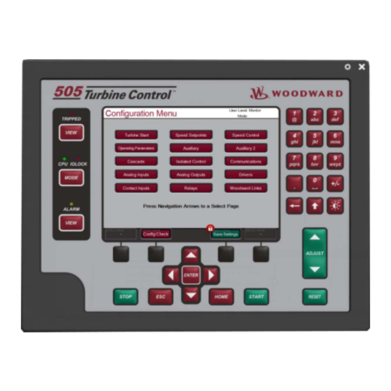
Woodward 505 Installation And Operation Manual (207 pages)
Digital Control for Steam Turbines
Brand:
Woodward
| Category:
Controller
| Size: 7.72 MB
Table of Contents
Table of Contents
3
Warnings and Notices
8
Electrostatic Discharge Awareness
10
Regulatory Compliance
11
Chapter 1. General Information
16
Introduction
16
Controller Overview
16
Figure 1-1. Typical Single or Dual Inlet Steam Turbine
17
Functional Block Diagrams
19
Figure 1-2. Explanation of Symbols
19
505 Inputs and Outputs
20
Figure 1-3. Single or Split-Range Turbine Configurations
20
Keypad and Display
25
Figure 1-4. 505 Keypad and Display
25
Watchdog Timer/Cpu Fault Control
26
Chapter 2. Hardware Specifications
27
Flex505 Description and Features
27
Figure 2-1. Functional Block Diagram (505D Control)
27
Environmental Specifications
28
Maintenance Info and Recommendations
28
Electromagnetic Compatibility (EMC)
29
Outline Drawing for Installation
29
Figure 2-2. 505D Outline Drawing
30
Input Power Specification
31
Visual Indicators (Led's) & CPU Configuration
32
Communications (Ethernet)
32
Communications (CAN)
33
Communications (RS-232/RS-485)
35
Communications (Service Ports)
36
Figure 2-3. COM1 Example RS-485 Wiring
36
Figure 2-4. CPU Service Port (3 Pin, 2 MM)
36
Hardware - Terminal Blocks & Wiring
37
Figure 2-5. 505 Back Cover Label
37
Terminal Block Connectors
38
Figure 2-6. Terminal Block Connectors
38
Hardware - Speed Sensor Inputs
39
Hardware - Analog Inputs (4-20 Ma)
40
Figure 2-7. Speed Sensor Block Diagram
40
Hardware - Analog Outputs (4-20 Ma)
41
Figure 2-8. Analog Input - Self-Powered Block Diagram
41
Figure 2-9. Analog Input - Loop-Powered Block Diagram
41
Hardware - Actuator Outputs
42
Figure 2-10. Analog Output Block Diagram
42
Hardware - Discrete Inputs
43
Figure 2-11. Actuator Output Block Diagram
43
Figure 2-12. Discrete Input Block Diagram
43
Hardware - Relay Outputs
44
Figure 2-13. Relay Output Block Diagram
44
Troubleshooting Fault Codes
45
Troubleshooting & Commissioning Checks
45
Chapter 3. 505 Control Description
49
Introduction
49
Turbine Start Modes
49
Start Permissive
49
Open Wire Detection on MPU Speed Signals
49
Zero Speed Signal Override
50
Manual Speed Override
50
Automatic Speed Override
50
Figure 3-1. Open Wire Detection Test
50
Acceleration Limiter
51
Turbine Start Mode Procedures
51
Figure 3-2. Manual Start Mode Example
52
Figure 3-3. Semiautomatic Start Mode Example
52
Figure 3-4. Automatic Start Mode Example
53
Figure 3-5. Idle/Rated Start
55
Figure 3-6. Automatic Start Sequence
56
Speed Control Overview
60
Speed PID Operational Modes
61
Figure 3-7. Speed Control Functional Diagram
61
Figure 3-8. Speed PID Control Modes
63
Figure 3-9. Frequency and Unit Load Relationship
64
Figure 3-10. Speed Relationships
66
Figure 3-11. Load Sharing Logic
72
Manual Demand
73
Load Rejection
73
Feed-Forward Input
74
Figure 3-12. Typical Anti-Surge Valve and Speed Feed-Forward Logic Trend
75
Cascade Control
76
Figure 3-13. Cascade Functional Diagram
76
Auxiliary Control
80
Figure 3-14. Aux Control Overview
81
Remote Auxiliary Set Point
84
Auxiliary 2 Control
85
Valve Limiter
86
Figure 3-15. Aux 2 Control Overview
86
Inlet Steam Pressure Compensation
87
Isolated PID Control
87
Emergency Shutdown
88
Controlled Shutdown
89
Overspeed Test Function
90
Local/Remote Function
90
Relays
91
Chapter 4. Configuration Procedures
94
Program Architecture
94
Display Modes and User Levels
94
Configuring the 505
95
Figure 4-1. Initial HOME Screen (Unit Not Configured)
95
Figure 4-2. Configuration Menu - Configuration Mode (Edit)
97
Exiting the Configure Mode
121
Valve/Actuator Calibration & Test
128
Calibration/Stroking Procedure
129
Chapter 5. 505 Operation
130
Software Architecture
130
Power-Up Screen
130
Figure 5-1. Software Architecture
130
Figure 5-2. 505 Splash Screen
131
Figure 5-3. Boot-Up to HOME Screen
131
Control Mode Architecture
132
Figure 5-4. Control Mode Architecture
132
User Login Levels
133
Figure 5-5. Mode Screen
133
Navigation
134
Page Organization
134
Figure 5-6. Navigation Cross
134
Figure 5-7. Service Menu Showing "Speed Control" IN-Focus
134
Figure 5-8. Configuration Menu - Operation Mode (View Only)
135
Figure 5-9. Configuration Menu - Configuration Mode (Edit)
135
Overview Screen
136
Figure 5-10. Overview Screen
136
Speed Control Screen
137
Valve Demand Screen
137
Figure 5-11. Speed Control Screen
137
Figure 5-12. Valve Demand Screen
137
Controllers Screen
138
Figure 5-13. Controllers Screen
138
Cascade Control Screen
139
Auxiliary Control Screen
139
Figure 5-14. Cascade Control Screen
139
Figure 5-15. Auxiliary Control Screen
139
Analog Input Summary Screen
140
Figure 5-16. Analog Input Summary Screen
140
Contact Input Summary Screen
141
Analog Output Summary Screen
141
Figure 5-17. Contact Input Summary Screen
141
Figure 5-18. Analog Output Summary Screen
141
Relay Output Summary Screen
142
Actuator Driver Summary Screen
142
Figure 5-19. Relay Output Summary Screen
142
Figure 5-20. Actuator Driver Summary Screen
142
Starting Procedures (Start Curve Screen)
143
Figure 5-21. HOME Menu Showing "Startup Curve" IN-Focus
143
Overspeed Test Function (Speed Control Screen)
144
Figure 5-22. Overspeed Test Permissives
144
Figure 5-23. Internal (505) Overspeed Test
145
Figure 5-24. External Overspeed Test
145
Stop Key
146
Alarm Summary
146
Figure 5-25. ALARM Screen
147
Shutdown Summary
151
Figure 5-26. Shutdown Summary Screen
151
Speed, Cascade, and Auxiliary Dynamics Adjustments
153
Figure 5-27. Speed Dynamics Adjustment Screen
153
Figure 5-28. Typical Response to Load Change
156
Figure 5-29. Overview of the Automated PID Optimizer Routine
157
Figure 5-30. Optimization Routine Overview Trend
158
Figure 5-31. Configuration Parameters 'Configure' Pop-Up
159
Chapter 6. Communications
166
Modbus Communications
166
Figure 6-1. ASCII/RTU Representation of Three
167
Table 6-2. Modbus Frame Definition
168
Port Adjustments
169
505 Control Modbus Addresses
169
Table 6-7. Boolean Write Addresses
170
Table 6-8. Boolean Read Addresses
172
Table 6-9. Analog Reads
176
Table 6-10. Analog Write Addresses
182
Table 6-12. Analog Input Configuration
183
Table 6-14. Relay Configured as Level Switch
184
Specific Address Information
185
Chapter 7. Product Support and Service Options
187
Product Support Options
187
Product Service Options
187
Returning Equipment for Repair
188
Replacement Parts
189
Engineering Services
189
Contacting Woodward's Support Organization
189
Technical Assistance
190
A Mode Worksheets
191
Declarations
205
Advertisement
Woodward 505 Installation And Operation Manual (176 pages)
Digital Governor for Steam Turbines with Single or Split-Range Actuators
Brand:
Woodward
| Category:
Control Unit
| Size: 1.75 MB
Table of Contents
Table of Contents
3
Electrostatic Discharge Awareness
7
Chapter 1. General Information
9
Introduction
9
General Description
11
Figure 1-1. Typical Single or Dual Inlet Steam Turbine
12
Figure 1-2. Split Range or Admission Type of Turbine Configuration
12
505 Inputs and Outputs
13
Control Overview
14
Figure 1-3A. Overview of 505 Functionality
15
Figure 1-3B. Overview of 505 Functionality
16
Speed Control
17
Auxiliary Control
17
Load Sharing Input
18
Cascade Control
18
Valve Limiter
18
Starting Features
19
Critical Speed Avoidance
19
Block Diagrams
20
Figure 1-4. Overview of 505 Functionality Notes
20
Figure 1-5. Single or Split-Range Turbine Configurations
21
Figure 1-6. Single or Split-Range Turbine Configurations
21
Keypad and Display
22
Figure 1-7. Single or Split-Range Turbine Configurations
22
Figure 1-8. 505 Key Pad and Display
22
Watchdog Timer/Cpu Fault Control
24
Chapter 2. Installation Procedures
25
Introduction
25
Mechanical Data and Hardware Installation
25
Figure 2-1. 505 Control Layout (Standard Enclosure)
27
Figure 2-2. 505 Bulkhead-Mounted Enclosure
28
Figure 2-3. Jumper Options
29
Figure 2-4. Jumper Locations
29
Figure 2-5. Cageclamp Terminal Blocks
31
Figure 2-6. Control Wiring Diagram
32
Figure 2-7. Representative 505 I/O Schematic
33
Figure 2-8. Fuse Location
34
Figure 2-9. Shielded Wire Connections
35
Figure 2-10. Typical RS-232 Communications
40
Figure 2-11. Typical RS-422 Communications
40
Communications Grounding and Shielding
41
Figure 2-12. Typical RS-485 Communications
41
Figure 2-13. Preferred Multipoint Wiring with a Separate Signal Ground Wire
41
Figure 2-14. Alternate Multipoint Wiring Without a Separate Signal Ground
42
Chapter 3. 505 Control Description
43
Introduction
43
Turbine Start
43
Figure 3-1. Basic Control Overview
43
Turbine Start Modes
45
Figure 3-2. Manual Start Mode Example
46
Figure 3-3. Semiautomatic Start Mode Example
47
Critical Speed Avoidance
48
Figure 3-4. Automatic Start Mode Example
48
Idle/Rated
49
Automatic Start Sequence
50
Figure 3-6. Automatic Start Sequence
51
No Idle Programmed
53
Speed Control Overview
53
Speed PID Operational Modes
54
Figure 3-7. Speed Control Functional Diagram
54
Figure 3-8. Speed PID Control Modes
55
Figure 3-9. Frequency and Unit Load Relationship
57
Figure 3-10. Speed Relationships
59
Figure 3-11. Loadsharing Logic
65
Cascade Control
66
Figure 3-12. Cascade Functional Diagram
67
Auxiliary Control
72
Figure 3-13. aux Control Overview
72
Remote Auxiliary Setpoint
76
Valve Limiter
78
Emergency Shutdown
78
Controlled Shutdown
79
Overspeed Test Function
80
Local/Remote Function
81
Function Keys
82
Relays
82
Chapter 4. Configuration Procedures
85
Program Architecture
85
Figure 4-1. Basic Program Architecture
85
Programming the 505
86
Figure 4-2. Initial 505 Program Mode Entry
86
Figure 4-3A. Program Mode Blocks
89
Figure 4-3B. Program Mode Blocks
90
Figure 4-3C. Program Mode Blocks
91
Figure 4-3D. Program Mode Blocks
92
Exiting the Program Mode
109
Figure 4-4. Exiting the Program Mode
109
Valve/Actuator Calibration & Test
113
Calibration/Stroking Procedure
114
Calibration/Stroking Procedure
116
Figure 4-5. Stroke Actuator
118
Figure 4-6. Stroking Dual Actuators
119
Chapter 5. 505 Operation
120
Run Mode Architecture
120
Figure 5-1. Basic Program Architecture
120
Figure 5-2A. Overview of Run Mode
121
Figure 5-2B. Overview of Run Mode
122
Figure 3-5. Idle/Rated Start
123
Keypad and Display
124
Run Mode Front Panel Keys
124
Figure 5-3. 505 Keypad and Display
124
Starting Procedures
125
Speed Key Screens
126
Figure 5-4. SPEED Key Screens
126
Figure 5-5. Direct Setpoint Entry
129
Overspeed Test Function
130
Figure 5-6. Overspeed Test Enable Key Screens
130
F3 and F4 Keys
131
Limiter (LMTR) Key Screens
131
Actuator (ACTR) Key Screens
132
Figure 5-7. LMTR Key Screens
132
Control (CONT) Key Screens
133
Dynamics (DYN) Key Screens
135
Stop Key Screens
136
Auxiliary (Aux) Key Screens
136
Remote/Speed Bias (RMT) Key Screens
139
Unit Load (KW) Key Screens
142
Cascade (CAS) Key Screens
143
Alarms
145
Trips
146
Speed, Cascade, and Auxiliary Dynamics Adjustments
147
Chapter 6. Communications
151
Modbus Communications
151
Port Adjustments
154
505 Control Modbus Addresses
154
Specific Address Information
165
Chapter 7. Service Options
167
Product Service Options
167
Woodward Factory Servicing Options
168
Returning Equipment for Repair
169
Replacement Parts
169
Engineering Services
170
How to Contact Woodward
170
Technical Assistance
171
Appendix . 505 Program Mode Worksheets
172
Declarations
175
Woodward 505 Product Manual (138 pages)
Digital Control for Steam Turbines
Brand:
Woodward
| Category:
Controller
| Size: 5.58 MB
Table of Contents
Table of Contents
3
Warnings and Notices
7
Electrostatic Discharge Awareness
8
Introduction
9
Chapter 8. Service Tools
10
Overview
10
Control Assistant (CA)
10
Servlink-To-OPC-Server (SOS)
10
Appmanager (Appman)
10
Chapter 9. Peripheral Devices
11
Overview
11
DSLC-2 (Generator Synchronizer and Load Control)
11
Figure 9-1. DSLC-2
11
Figure 9-2. Configuration/Woodward Links/Dslc-2
12
Figure 9-3. Service Screen - DSLC-2 Power Parameters
12
Varistroke II (Electro-Hydraulic Actuator)
13
Figure 9-4. Service Screen - DSLC-2 Status Parameters
13
Figure 9-5. VS-II
13
Figure 9-6. Configuration/Woodward Links/Vs-II
14
Figure 9-7. Service/Varistroke II
14
MFR300 (Multi-Function Relay)
15
Protection/Breaker Control Relay)
15
Servo Position Controller (SPC)
15
Figure 9-8. Multi-Function Relay
15
Figure 9-9. LS-5
15
Real Power Sensor
16
Figure 9-10. Servo Position Controller
16
Figure 9-11. Interface to Servo Position Controller
16
Engine Generator Control Package/Load Sharing (EGCP-3 LS)
17
Figure 9-12. Real Power Sensor
17
Figure 9-13. EGCP-3 Control
18
Figure 9-14. EGCP-3 LS Functional Diagram
19
Figure 9-15. EGCP-3 LS Interface Wiring
20
Applying the 505 with Redundant I/H or I/P Converters
21
Figure 9-16. Typical Redundant I/H System with a Transfer Valve
21
Figure 9-17. Typical Redundant I/P System with a Pressure Selecting Relay Valve
21
Chapter 10. Application Notes
23
Overview
23
Example Applications
24
Figure 10-1. Pump or Compressor Discharge Pressure Control with Turbine Inlet Pressure Limiting
26
Figure 10-2. Inlet Pressure Control with Automaticsynchronizing & Generator Power Limiting
29
Figure 10-3. Exhaust Pressure Control with Generator Power Limiting and Plant Import/Export Limiting
33
Figure 10-4. Plant Import/Export Control with DRFD Servo Interface
37
Figure 10-5. Inlet Pressure Control with Isochronous Loadsharing Control in Island Mode
41
Figure 10-6. Import/Export Control or Exhaust Pressure Control with Isoch Load Sharing in Island Mode
44
Chapter 11. Operator Interface
48
Introduction
48
Graphical Display and Key Inputs
48
Figure 11-1 505 Keypad and Display
48
Service Panel Modes and User Levels
49
Chapter 12. Service Menu Procedures
51
Overview
51
Using the Service Menus
51
Figure 12-1. User Login for Service
51
Figure 12-2. Authorized and Unauthorized Components
52
Figure 12-3 Service Menu
52
Figure 12-4 Service Menu
53
Service Mode Parameters
55
Chapter 13. Understanding Pid Settings
75
Overview
75
Proportional Response
76
Figure 13-1. Proportional Gain Setting Effects
76
Proportional + Integral (Closed Loop)
77
Figure 13-2. Open Loop Proportional and Integral Response
77
Figure 13-3. Closed Loop Proportional and Integral Response
78
Derivative Response
79
Figure 13-4. Integral Gain (Reset) Setting Responses
79
Proportional + Derivative (Closed Loop)
80
Figure 13-5. Closed Loop Proportional and Derivative Action
80
Proportional + Integral + Derivative (Closed Loop)
81
Figure 13-6. Derivative Setting Effects
81
Figure 13-7. Closed Loop Proportional, Integral and Derivative Action
82
Controller Field Tuning General
83
Figure 13-8. Typical Response to Load Change
83
Chapter 14. Hardware/Operating System Faults
85
General
85
Wiring Problems
85
Control Adjustments
85
Other Operating Problems
86
505 Design Specifications
87
Hardware Specifications
87
Software Specifications
87
505 Service Mode Worksheet
89
Appendix D. Password Information
99
General
99
Monitor User Level
99
Operator" User Level Password
99
Service" User Level Password
99
Configure" User Level Password
99
Serviceuser" User Level Password
99
Appendix E. Servlink-To OPC Server (SOS) Tool
100
SOS Communication Link
100
Installing SOS
100
Figure E-1. SOS
100
Connecting a Pc/Laptop to the Control
101
Figure E-2. SOS Install Window
101
Figure E-3. SOS Server Status Dialog Box
101
Figure E-4. SOS - New Session Box
102
Figure E-5. SOS - Enter 505 TCP/IP Address
102
Figure E-6. SOS - Active Links Dialog Box
102
Appendix F. Control Assistant-Software Interface Tool
104
Features of Control Assistant
104
Installing Control Assistant
104
Figure F-1. Control Assistant License Agreement
104
Figure F-2. Control Assistant Install Window
105
Figure F-3. Control Assistant Folder Selection
105
Figure F-4. Control Assistant Install Complete
105
Using Control Assistant
106
Figure F-5. Install Restart Window
106
Figure F-6. Control Assistant Window
106
Figure F-7. Dialog for Servlink OPC Connection
107
Figure F-8. Winpanel Session
107
Figure F-9. Control Assistant - Retrieve Tunable Dialog Box
108
Figure F-10. Control Assistant - Send Tunable Dialog Box
109
Figure F-11. Control Assistant - Speed Control Trend Script
110
Figure F-12. Control Assistant - Create Trend Script File
110
Appendix G. Appmanger Service Tool
111
File Management with App. Manager
111
Installing App Manager
111
Figure G-1. App Manager Install Window
111
Figure G-2. App Manager License Agreement Window
112
Figure G-3. App Manager Installation
112
Figure G-4. App Manager Install Complete
113
Figure G-5. Appmanager Window
113
Figure G-6. Dialog for App Manager Connection
114
Figure G-7. App Manager Connected to a Control
114
Figure G-8. Appmanager Control Info Window
115
Figure G-9. Appmanager Control (GAP) Application Panel
115
Figure G-10. Appmanager GUI Application Panel
116
Figure G-11. Retrieving Files
116
Appendix H. Configuring Network Tcp/Ip Addresses
118
Figure H-1. Configuration/Communications Screen
118
Figure H-2. Ethernet Port Layout (Ports on Side)
118
Appendix I. Remoteview Tool
120
Figure I-1. Window Shown When the Time Limit Is Exceeded
120
Figure I-2. Installation Welcome Window
120
Figure I-3. Installation Folder Window
121
Figure I-4. Installation License Agreement Window
121
Figure I-5. Installation Start Menu Shortcuts Window
122
Figure I-6. Installation Ready to Install Window
122
Figure I-7. Installation Complete Window
123
Figure I-8. Entering an IP Address to be Added to the Control List
123
Figure I-9. Control Selected in the Control List
124
Figure I-10. Login Window with Fields for User Name and Password
124
Figure I-11. an Application Selected in the Application List
125
Figure I-12. Default View of the Tool
126
Figure I-13. Simple View of the Tool
126
Figure I-14. Full View of the Tool
127
Figure I-15. Entering a Name for the Current Settings
127
Figure I-16. a New Settings File Entered in the Predefined Settings List
128
Figure I-17. Remote View Tool (Default Setting) after Opening from the Configuration Window
129
Appendix J. Using 505 Internal Simulation Mode
130
Figure J-1. HW Simulation Mode Access
130
Appendix K. Custom Tag Name Procedure
131
Appendixl Datalogs
132
Figure K-1. the Datalog Service Menu Page
133
Figure K-2. Datalog Graph Properties
134
Figure K-3. Datalog Plot
135
Figure K-4. Automated File Collection Configuration
136
Figure K-5. Automated File Collection Active
137
Advertisement
Woodward 505 Product Manual (138 pages)
Digital Control for Steam Turbines
Brand:
Woodward
| Category:
Controller
| Size: 4.4 MB
Table of Contents
Table of Contents
3
Warnings and Notices
7
Electrostatic Discharge Awareness
8
Introduction
9
Volume
9
Chapter 1. Service Tools
10
Overview
10
Control Assistant (CA)
10
Servlink-To-OPC-Server (SOS)
10
Appmanager (Appman)
10
Chapter 2. Peripheral Devices
11
Overview
11
DSLC-2 (Generator Synchronizer and Load Control)
11
Figure 2-1. DSLC-2
11
Figure 2-2. Configuration/Woodward Links/Dslc-2
12
Figure 2-3. Service Screen - DSLC-2 Power Parameters
12
Varistroke II (Electro-Hydraulic Actuator)
13
Figure 2-4. Service Screen - DSLC-2 Status Parameters
13
Figure 2-5. VS-II
13
Figure 2-6. Configuration/Woodward Links/Vs-II
14
Figure 2-7. Service/Varistroke II
14
MFR300 (Multi-Function Relay)
15
Protection/Breaker Control Relay)
15
Servo Position Controller (SPC)
15
Figure 2-8. Multi-Function Relay
15
Figure 2-9. LS-5
15
Figure 2-10. Servo Position Controller
16
Figure 2-11. Interface to Servo Position Controller
16
Real Power Sensor
17
Figure 2-12. Real Power Sensor
17
Engine Generator Control Package/Load Sharing (EGCP-3 LS)
18
Figure 2-13. EGCP-3 Control
19
Figure 2-14. EGCP-3 LS Functional Diagram
19
Figure 2-15. EGCP-3 LS Interface Wiring
20
Applying the 505 with Redundant I/H or I/P Converters
21
Figure 2-16. Typical Redundant I/H System with a Transfer Valve
21
Figure 2-17. Typical Redundant I/P System with a Pressure Selecting Relay Valve
22
Chapter 3. Application Notes
23
Overview
23
Example Applications
24
Figure 3-1. Pump or Compressor Discharge Pressure Control with Turbine Inlet Pressure Limiting
26
Figure 3-2. Inlet Pressure Control with Automatic Synchronizing & Generator Power Limiting
29
Figure 3-3. Exhaust Pressure Control with Generator Power Limiting and Plant Import/Export Limiting
33
Figure 3-4. Plant Import/Export Control with DRFD Servo Interface
38
Figure 3-5. Inlet Pressure Control with Isochronous Loadsharing Control in Island Mode
42
Figure 3-6. Import/Export Control or Exhaust Pressure Control with Isoch Load Sharing in Island Mode
45
Chapter 4. Operator Interface
50
Introduction
50
Graphical Display and Key Inputs
50
Figure 4-1 505 Keypad and Display
50
Service Panel Modes and User Levels
51
Chapter 5. Service Menu Procedures
53
Overview
53
Using the Service Menus
53
Figure 5-1. User Login for Service
53
Figure 5-2. Authorized and Unauthorized Components
54
Figure 5-3 Service Menu
55
Figure 5-4 Service Menu
55
Service Mode Parameters
58
Chapter 6. Understanding Pid Settings
80
Overview
80
Proportional Response
81
Figure 6-1. Proportional Gain Setting Effects
81
Figure 6-2. Open Loop Proportional and Integral Response
82
Proportional + Integral (Closed Loop)
83
Figure 6-3. Closed Loop Proportional and Integral Response
83
Derivative Response
84
Figure 6-4. Integral Gain (Reset) Setting Responses
84
Proportional + Derivative (Closed Loop)
85
Figure 6-5. Closed Loop Proportional and Derivative Action
86
Figure 6-6. Derivative Setting Effects
86
Proportional + Integral + Derivative (Closed Loop)
87
Figure 6-7. Closed Loop Proportional, Integral and Derivative Action
87
Controller Field Tuning General
88
Figure 6-8. Typical Response to Load Change
89
Chapter 7. Hardware/Operating System Faults
91
General
91
Wiring Problems
91
Control Adjustments
92
Other Operating Problems
92
505 Design Specifications
93
A Ppendix A. 505 D Esign S Pecifications
93
505 Service Mode Worksheet
94
Hardware Specifications
93
Software Specifications
93
Appendix C. Password Information
104
General
104
Monitor User Level
104
Operator User Level Password
104
Service User Level Password
104
Configure User Level Password
104
Serviceuser Mode Password
104
Appendix D. Servlink-To OPC Server (SOS) Tool
105
Figure D-1. SOS
105
Installing SOS
105
SOS Communication Link
105
Connecting a Pc/Laptop to the Control
106
Figure D-2. SOS Install Window
106
Figure D-3. SOS Server Status Dialog Box
106
Figure D-4. SOS - New Session Box
107
Figure D-5. SOS - Enter 505 TCP/IP Address
107
Figure D-6. SOS - Active Links Dialog Box
107
Appendix E. Control Assistant-Software Interface Tool
108
Features of Control Assistant
108
Figure E-1. Control Assistant License Agreement
108
Installing Control Assistant
108
Figure E-2. Control Assistant Install Window
109
Figure E-3. Control Assistant Folder Selection
109
Figure E-4. Control Assistant Install Complete
109
Figure E-5. Install Restart Window
110
Figure E-6. Control Assistant Window
110
Using Control Assistant
110
Figure E-7. Dialog for Servlink OPC Connection
111
Figure E-8. Winpanel Session
111
Figure E-9. Control Assistant - Retrieve Tunable Dialog Box
112
Figure E-10. Control Assistant - Send Tunable Dialog Box
113
Figure E-11. Control Assistant - Speed Control Trend Script
114
Figure E-12. Control Assistant - Create Trend Script File
115
Appendix F. Appmanger Service Tool
116
Figure F-1. App Manager Install Window
116
File Management with App. Manager
116
Installing App Manager
116
Figure F-2. App Manager License Agreement Window
117
Figure F-3. App Manager Installation
117
Figure F-4. App Manager Install Complete
117
Figure F-5. Appmanager Window
118
Figure F-6. Dialog for App Manager Connection
118
Figure F-7. App Manager Connected to a Control
119
Figure F-8. Appmanager Control Info Window
119
Figure F-10. Appmanager GUI Application Panel
120
Figure F-9. Appmanager Control (GAP) Application Panel
120
Figure F-11. Retrieving Files
121
Appendix G. Configuring Network Tcp/Ip Addresses
123
Figure G-1. Configuration/Communications Screen
123
Figure G-2. Ethernet Port Layout (Ports on Side)
123
Appendix H. Remoteview Tool
125
Figure H-1. Window Shown When the Time Limit Is Exceeded
125
Figure H-2. Installation Welcome Window
125
Figure H-3. Installation Folder Window
126
Figure H-4. Installation License Agreement Window
126
Figure H-5. Installation Start Menu Shortcuts Window
127
Figure H-6. Installation Ready to Install Window
127
Figure H-7. Installation Complete Window
128
Figure H-8. Entering an IP Address to be Added to the Control List
129
Figure H-9. Control Selected in the Control List
129
Figure H-10. Login Window with Fields for User Name and Password
130
Figure H-11. an Application Selected in the Application List
131
Figure H-12. Default View of the Tool
132
Figure H-13. Simple View of the Tool
132
Figure H-14. Full View of the Tool
133
Figure H-15. Entering a Name for the Current Settings
133
Figure H-16. a New Settings File Entered in the Predefined Settings List
134
Figure H-17. Remote View Tool (Default Setting) after Opening from the Configuration Window
135
Appendix I. Using 505 Internal Simulation Mode
136
Figure I-1. HW Simulation Mode Access
136
Appendix J. Custom Tag Name Procedure
137
Required Tools
137
Creating Custom Tags
137
Woodward 505 Installation And Operation Manual (124 pages)
Digital Governor for Steam Turbines with Single or Split-Range Actuators
Brand:
Woodward
| Category:
Controller
| Size: 1.91 MB
Table of Contents
Table of Contents
3
Electrostatic Discharge Awareness
5
Introduction
7
Chapter 1. Peripheral Devices
8
Overview
8
505 HMI Software
8
Figure 1-1. 505 HMI Software
9
Figure 1-2. Digital Remote Final Driver
10
Figure 1-3. Real Power Sensor
11
Figure 1-4A. Digital Synchronizer and Load Control
13
Figure 1-4B. Digital Synchronizer and Load Control Functional Diagram
14
Figure 1-5. DSLC Interface Wiring
15
Figure 1-6A. Master Synchronizer and Load Control
16
Figure 1-6B. Master Synchronizer and Load Control Functional Diagram
17
Chapter 2. Application Notes
18
Overview
18
Example Applications
19
Figure 2-1. Pump or Compressor Discharge Pressure Control with Turbine Inlet Pressure Limiting
21
Figure 2-2. Inlet Pressure Control with Automatic Synchronizing & Generator Power Limiting
24
Figure 2-3. Exhaust Pressure Control with Generator Power Limiting and Plant Import/Export Limiting
28
Figure 2-4. Plant Import/Export Control with DRFD Servo Interface
33
Figure 2-5. Inlet Pressure Control with Isochronous Loadsharing Control in Island Mode
37
Figure 2-6. Import/Export Control or Exhaust Pressure Control with Isoch Load Sharing in Island Mode
40
Chapter 3. Operator Interface
45
Introduction
45
Keypad and Display
45
Figure 3-1. 505 Keypad and Display
45
Service Panel Modes
46
Using the Service Mode
46
Figure 3-2. Software Structure Overview
47
Figure 3-3. the Select Mode Level
48
Figure 3-4. Header Level
48
Figure 3-5. Block Level
49
Figure 3-6. Debug Information Arrangement
55
Figure 3-7. OS_FAULTS Mode Information Arrangement
56
Figure 3-8. SYS_INFO Mode Information Arrangement
61
Chapter 4. Service Mode Procedures
66
Overview
66
Figure 4-1. Service Mode Entry
66
The 505 Service Mode
67
Figure 4-2A. Service Mode Blocks
67
Figure 4-2B. Service Mode Blocks
68
Figure 4-2C. Service Mode Blocks
69
Figure 4-2D. Service Mode Blocks
70
Figure 4-2E. Service Mode Blocks
71
Figure 4-2F. Service Mode Blocks
72
Figure 4-2G. Service Mode Blocks
73
Figure 4-2H. Service Mode Blocks
74
Figure 4-2I. Service Mode Blocks
75
Service Mode Blocks
76
Service Mode Worksheet Parameters
78
Chapter 5. Understanding Pid Settings
98
Overview
98
Proportional Response
99
Figure 5-1. Proportional Gain Setting Effects
99
Figure 5-2. Open Loop Proportional and Integral Response
100
Proportional + Integral (Closed Loop)
101
Figure 5-3. Closed Loop Proportional and Integral Response
101
Derivative Response
102
Figure 5-4. Integral Gain (Reset) Setting Responses
102
Proportional + Derivative (Closed Loop)
103
Figure 5-5. Closed Loop Proportional and Derivative Action
104
Figure 5-6. Derivative Setting Effects
104
Proportional + Integral + Derivative (Closed Loop)
105
Figure 5-7. Closed Loop Proportional, Integral and Derivative Action
105
Controller Field Tuning General
106
Figure 5-8. Typical Response to Load Change
107
Chapter 6. Hardware/Operating System Faults
109
General
109
505 Design Specifications
113
Hardware Specifications
113
Software Specifications
116
505 Service Mode Worksheet
117
Appendix C. Password Information
120
General
120
Service Mode Password
120
Debug Mode Password
120
Configure Mode Password
121
OS_FAULTS Mode Password
121
Download Configuration Function Password
121
Woodward 505 Installation Procedure Supplement (5 pages)
Enhanced Digital Control for Steam Turbines
Brand:
Woodward
| Category:
Controller
| Size: 0.3 MB
Advertisement
Related Products
Woodward TecJet 52
Woodward PGA-EG 500
Woodward 505D
Woodward 505E
Woodward TecJet 50
Woodward 505XT
Woodward 505HT
Woodward TecJet 50 Plus
Woodward 5448-882
Woodward 5448-880
Woodward Categories
Controller
Control Unit
Relays
Control Systems
Industrial Equipment
More Woodward Manuals
Login
Sign In
OR
Sign in with Facebook
Sign in with Google
Upload manual
Upload from disk
Upload from URL