Woodward 505E Manual
Digital governors for extraction steam turbines
Hide thumbs
Also See for 505E:
- Installation and operational manual (218 pages) ,
- Product manual (20 pages)

Related Manuals for Woodward 505E


Summary of Contents for Woodward 505E
- Page 1 85018V2A 505E DIGITAL GOVERNORS FOR EXTRACTION STEAM TURBINES VOLUME 2 Manual 85018V2A...
- Page 2 CHANGED AREAS ARE INDICATED BY A BLACK LINE IN THE MARGIN. Woodward Governor Company reserves the right to update any portion of this publication at any time. Information provided by Woodward Governor Company is believed to be correct and reliable. However, no responsibility is assumed by Woodward Governor Company unless otherwise expressly undertaken.
-
Page 3: Table Of Contents
EXAMPLE 1 PUMP OR COMPRESSOR DISCHARGE PRESSURE CONTROL WITH TURBINE INLET PRESSURE LIMITING..........................19 505E Configuration Notes for Example 1: ................... 21 Starting & Run Mode Notes for Example 1:..................23 EXAMPLE 2 NLET PRESSURE CONTROL WITH AUTOMATIC SYNCHRONIZING & GENERATOR POWER LIMITING ............................. - Page 4 Change Password Header ......................94 Download Configuration Header ....................95 CHAPTER 4. SERVICE MODE PROCEDURES..................97 OVERVIEW..............................97 THE 505E SERVICE MODE ........................98 Using Service Menus........................... 98 SERVICE MODE BLOCKS ........................107 Optional Service Blocks........................107 SERVICE MODE WORKSHEET PARAMETERS..................109 Speed Control Settings........................
- Page 5 APPENDIX A. 505E DESIGN SPECIFICATIONS.................. 151 HARDWARE SPECIFICATIONS ......................153 GENERAL I/O SPECIFICATIONS ......................155 SOFTWARE SPECIFICATIONS......................157 APPENDIX B. 505E SERVICE MODE WORKSHEET................159 APPENDIX C. PASSWORD INFORMATION..................165 GENERAL ..............................167 SERVICE MODE PASSWORD........................ 167 DEBUG MODE PASSWORD........................167 CONFIGURE MODE PASSWORD......................
- Page 6 505E Digital Governor Manual 85018V2 Woodward...
- Page 7 2-8. Admission Steam Turbine Control with Bootstrap Startup ............66 2-9. Plant Load and Steam Pressure Control Application ..............71 3-1. 505E Keypad and Display......................75 3-2. Software Structure Overview ......................76 3-3. The Select Mode Level ......................... 78 3-4.
- Page 8 505E Digital Governor Manual 85018V2 Woodward...
- Page 9 Manual 85018V2 505E Digital Governor LIST OF TABLES 2-1. Example Summary........................18 Woodward...
- Page 10 505E Digital Governor Manual 85018V2 viii Woodward...
-
Page 11: Introduction
Manual 85018V2 Volume #2 is a dual purpose manual. This manual includes application specific notes and 505E specific Service mode information. The first part of this manual is written to give users an idea of the 505E Digital Control’s capabilities, and how to apply them to a system. Typical applications are schematically shown and their functionality explained. - Page 12 505E Digital Governor Manual 85018V2 Woodward...
-
Page 13: Chapter 1. Peripheral Devices
OVERVIEW This chapter provides a brief explanation of peripheral devices, that can be used with the 505E. By understanding the functionality of a peripheral device, a better understanding of the overall control configuration can be achieved. All the devices covered in this section are manufactured or supported by the Woodward Governor Company. -
Page 14: Hmi Software
By connecting the OpView or 505View to either 505E Modbus® port, it automatically configures its screens to match the 505E’s programmed application. If the 505E is not configured to accept Modbus commands, the HMI functions as a system monitor only. If the 505E is configured to accept Modbus commands, all 505E Run Mode operations can be monitored and performed through it (start, stop, mode enable/disable, setpoint raise/lower). -
Page 15: Digital Remote Final Driver
Integrating type DRFDs sense actual valve position (through, LVDTs, RVDTs, MLDTs, or DC position feedback devices), compare this signal to the input position demand signal from the 505E, and output a drive signal to position a servo assembly accordingly. See Figure 1-2. -
Page 16: Real Power Sensor
4-20mA output proportional to real power. Figure 1-3. Real Power Sensor Woodward manufactures two types of Real Power Sensors. The first type of RPS is designed to sense power flow in one direction only (0 to +5Amp CT current only), and output a proportional 4-20mA signal. -
Page 17: Digital Synchronizer And Load Control (Dslc)
VAR/PF control, and a process control, integrated into one package. The 505E can be programmed to use the DSLC as a synchronizer only, or as a synchronizer and load control. The DSLC provides either phase match or slip frequency synchronizing, and ties into the unit automatic voltage regulator to match voltages before paralleling. - Page 18 DSLC’s Process control mode allows any process directly related to generator load to be controlled. When using the DSLC as both a synchronizer and load control, the 505E control must be programmed to receive the DSLC Speed Bias signal through an analog input and have this input enabled through a contact input or function key.
- Page 19 Manual 85018V2 505E Digital Governor Figure 1-4a. Digital Synchronizer and Load Control Woodward...
- Page 20 Hand-held Programmer (9905-292) is required and used by the DSLC to configure and calibrate it to the site specific application. The DSLC requires a power source of +24Vdc @ 1Amp. The 505E power supplies can not supply this much power, thus an external power supply may be required.
-
Page 21: Master Synchronizer And Load Control (Mslc)
Manual 85018V2 505E Digital Governor Figure 1-5. DSLC Interface Wiring Master The Woodward MSLC is a microprocessor based plant load control designed for Synchronizer and use in three-phase electric power generation sites equipped with Woodward Load Control DSLCs which operate in parallel with the utility. The MSLC is a tie-line... - Page 22 505E Digital Governor Manual 85018V2 The MSLC’s baseload mode of operation allows an operator to set the plant to a specified load. A proportional or integrating control action can be used with this mode of operation. The integrating mode of operation can be used with systems tying to an unstable grid to allow the plant to control at a constant load and not vary based on grid frequency.
- Page 23 Because the MSLC/DSLC network only allows one master controller at a time, only one MSLC at a time can be utilized to control plant load. For more information on Woodward’s Master Synchronizer & Load Control and how to apply it, please refer to Woodward manual 02022.
- Page 24 Hand-held Programmer (9905-292) is required and used by the MSLC to configure and calibrate it to the site specific application. The MSLC requires a power source of +24Vdc @ 1Amp. The 505E power supplies can not supply this much power, thus an external power supply may be required.
-
Page 25: Chapter 2. Application Notes
A combination of the Speed PID and its setpoint limits allow this PID to limit unit load. When used as a unit load limiter, it is recommended that the 505E be configured to sense and control only true generator load. If applying the 505E system to a soft grid, where the utility frequency varies greatly, it is recommended that unit load limiting be performed by the Auxiliary PID - not the Speed PID. -
Page 26: Auxiliary Pid
Modbus communications. With this configuration when the Aux PID is enabled the Speed PID is disabled and tracks the Auxiliary PID’s output. To control or limit any of the listed parameters, the 505E must be programmed to accept an Auxiliary analog input signal representing that parameter’s level. The... -
Page 27: Example Applications
Any process parameter related to unit load, inlet pressure, or exhaust pressure (depending on the configuration) The 505E’s Cascade PID can be used to control any of the listed parameters. This PID must be enabled and disabled by commands given through the 505E’s front panel, contact input, or Modbus communications. - Page 28 505E Digital Governor Manual 85018V2 The features and functionality shown in each example are summarized in table 2-1. Table 2-1. Example Summary Woodward...
-
Page 29: Pressure Limiting
Pressure Limiting This is an example of a typical pump or compressor application. With this application the 505E is configured to normally control pump/compressor discharge pressure, extraction pressure, and limit governor valve position based on low turbine inlet steam pressure. Both the Auxiliary and Cascade modes were used for this example application. - Page 30 In all cases the 505E starts up with the Extr/Adm PID disabled and the LP valve at its maximum open position. This allows a turbine to warm-up in a uniform manner. With this application the Extr/Adm setpoint is only varied through the 505E’s front panel.
-
Page 31: Configuration Notes For Example 1
Since a two wire, loop powered transducer was used to sense extraction pressure, the 505E back cover was removed, JPR11 was removed, and JPR10 was installed. Because of where the extraction transducer was placed with respect to the LP valve (refer to Figure 2-1) no input inversion was required. - Page 32 505E back cover was removed, JPR9 was removed, and JPR8 as installed. The 505E was configured to accept a contact from a panel mounted switch to externally enable and disable discharge pressure control. (Contact Input 1 Function: Casc Control Enable) Pump/compressor discharge pressure is directly proportional to turbine inlet valve position, thus input inversion is not required.
-
Page 33: Starting & Run Mode Notes For Example 1
#3 Energizes on - Shutdown Condtion) Relay #4 was programmed to indicate a 505E initated trip as follows: (Relays: Use Relay #4 - Yes ; Relay #4 is a Level Switch? - No ; Relay #4 Energizes on - Trip... - Page 34 Manual 85018V2 The enabling routine, which automatically lowers the LP valve limiter, may be issued from the 505E’s service panel, contact input, or through Modbus communications. This routine automatically ramps the LP valve to its minimum position and may be stopped at any time by momentarily issuing a LP valve limiter raise or lower command.
-
Page 35: Power Limiting
Manual 85018V2 505E Digital Governor EXAMPLE 2 NLET (Extraction Turbine, Decoupled Inlet mode) PRESSURE CONTROL WITH AUTOMATIC SYNCHRONIZING & GENERATOR POWER LIMITING Figure 2-2. Inlet Pressure Control with Automatic Synchronizing & Generator Power Limiting Woodward... - Page 36 In all cases the 505E starts up with the Extr/Adm PID disabled and the LP valve at its maximum open position. This allows a turbine to warm-up in a uniform manner. With this application the Extr/Adm setpoint is only varied through the 505E’s front panel.
-
Page 37: Configuration Notes For Example 2
Without this actual unit load input, a calculated load percentage is displayed. The RPS and associated load input are not required by the 505E for control, this input is only used for monitor and display purposes. The 505E was configured to receive a generator load signal from a Real Power Sensor through Analog Input #2. - Page 38 505E back cover was removed, JPR9 was removed, and JPR8 was installed. The 505E was configured to accept a contact from a panel mounted switch to externally enable and disable inlet header pressure control. (Contact Input #3 Function: Casc Control Enable)
- Page 39 This is considered an indirect action and requires the input to be inverted. (Invert Cascade Input? - Yes) With this application, Setpoint Tracking is used to allow the 505E to track inlet header pressure before being enabled, thus allowing a bumpless transfer to inlet header pressure control.
-
Page 40: Starting & Run Mode Notes For Example 2
When the plant-to-utility tie-line breaker is closed and the unit generator breaker closes, the 505E steps the speed/load setpoint up to a minimum load level to reduce the chance of reverse powering or motoring the generator. This minimum load level is based on the speed/load setpoint and is defaulted to “3%”. - Page 41 505E Digital Governor If an operator chooses to use the automatic enabling routine to lower the LP valve limiter, he may issue an Extraction enable command from the 505E’s service panel, contact input, or through Modbus communications. This routine automatically ramps the LP valve to its minimum position and may be stopped at any time by momentarily issuing a LP valve limiter raise or lower command.
-
Page 42: Example 3 Exhaust Pressure Control With Plant Import/Export Limiting
505E Digital Governor Manual 85018V2 EXAMPLE 3 (Extraction Turbine, Decoupled Exhaust) EXHAUST PRESSURE CONTROL WITH PLANT IMPORT/ EXPORT LIMITING Figure 2-3. Exhaust Pressure Control with Generator Power Limiting and Plant Import/Export Limiting Woodward... - Page 43 Because the Auxiliary PID is the only 505E controller that has this limiting capability, it was used to sense tie line power and limit turbine/generator output, based on a zero export limit setting.
-
Page 44: Configuration Notes For Example 3
505E Digital Governor Manual 85018V2 The following list of notes are provided as a reference for application programmers to follow when programming the 505E to achieve the control and limiting actions shown in Figure 2-3. 505E OPERATING PARAMETERS: Configuration This is a Generator application. (Generator Application? - Yes) - Page 45 Since a two wire, loop powered transducer was used to sense the pressure level, the 505E back cover was removed, JPR9 was removed, and JPR8 was installed. The Function Key F3 was programmed to allow an operator to easily enable...
-
Page 46: Starting & Run Mode Notes For Example 3
+5A CT current (Input #3 20mA Value = +XXXX) Because the RPS’s KW readout is self powered, the 505E back cover was removed, JPR14 was removed, and JPR15 was installed. The utility-tie Real Power Sensor’s CT inputs were wired to allow the RPS’s 4mA value to represent full import power and the RPS’s 20mA value to... - Page 47 When the plant to utility tie line/breaker is closed, and the unit generator breaker closes, the 505E steps the speed/load setpoint up to a minimum load level to reduce the chance of reverse powering or motoring the generator. This minimum load level is based on the speed/load setpoint and is defaulted to a “3%”...
- Page 48 When paralleled to the utility this 505E and RPS combination allows the plant to import power from the utility, but not export power. If the utility-to-plant tie line power reaches a zero import/export level, the Auxiliary PID will begin limiting generator output until plant conditions require power to be imported again.
-
Page 49: Example 4 Plant Import/Export Control With Drfd Servo Interface
Manual 85018V2 505E Digital Governor EXAMPLE 4 (Adm or Extr/Adm Turbine, Coupled HP & LP mode) PLANT IMPORT/ EXPORT CONTROL WITH DRFD SERVO INTERFACE Figure 2-4. Plant Import/Export Control with DRFD Servo Interface Woodward... - Page 50 When programmed for this type of control action, the Speed PID is disabled when the Auxiliary PID is enabled and can only limit the 505E’s valve output signal if unit load reaches 100%. Also, the Auxiliary setpoint automatically tracks the Auxiliary PID’s input value when not in-control.
-
Page 51: Configuration Notes For Example 4
Modbus command, or the 505E service panel. As shown in Figure 2-4, a panel mounted (DPST) switch is used with this application to select automatic synchronization in both the DSLC and the 505E. - Page 52 This application’s turbine has the capability for controlled extraction or admission steam. (Extraction & Admission? - Yes) With this application, Setpoint Tracking is used to allow the 505E to track header pressure before being enabled, thus allowing a bumpless transfer into header pressure control.
- Page 53 4-20mA valve demand signal. ( Act #1 (HP) is 4- 20ma? - Yes ), ( Act #2 (LP) is 4-20ma? - Yes ) Dither is a low frequency AC current modulated on to the 505E’s DC actuator-drive current to reduce stiction in linear type actuators. Because the 505E’s actuator output is connected to the DRFD, dither was not required or...
-
Page 54: Starting & Run Mode Notes For Example 4
DSLCs to perform safe dead bus closing. When the plant-to-utility tie line/breaker is closed and the unit generator breaker closes, the 505E steps the speed/load setpoint up to a minimum load level to reduce the chance of reverse powering or motoring the generator. This minimum load level is based on the speed/load setpoint and is defaulted to a “3% or xxx... - Page 55 Adm Trip-&-Throttle valve should be matched. The 505E has a manual demand signal to allow operators to manually vary the pressure on the turbine side of the Adm T&T valve. Once these pressures are matched the operator can open the T&T valve, and then issue an Extr/Adm...
-
Page 56: Island Mode
505E Digital Governor Manual 85018V2 EXAMPLE 5 (Extraction Turbine, Decoupled Inlet mode, Coupled HP & LP mode) INLET PRESSURE CONTROL WITH ISOCHRONOUS LOADSHARING CONTROL IN ISLAND MODE Figure 2-5. Inlet Pressure Control with Isochronous Loadsharing Control in Island Mode Woodward... - Page 57 In all cases the 505E starts up with the Extr/Adm PID disabled and the LP valve at its maximum open position. This allows a turbine to warm-up in a uniform manner. With this application the Extr/Adm setpoint is only varied through the 505E’s front panel.
-
Page 58: Programming Notes For Example 5
DSLC. This synchronizing function/input can be enabled through a contact input, function key, Modbus command, or the 505E service panel. As shown in Figure 2-5 a panel mounted (DPST) switch is used with this application to select automatic synchronization in both the DSLC and 505E. - Page 59 Input) he input’s 4mA and 20mA values were programmed based on what the pressure transducer was ranged/calibrated for. Because a two wire, loop powered transducer is used to sense the pressure level, the 505E back cover was removed, JPR9 was removed, and JPR8 was installed. Woodward...
- Page 60 505E Digital Governor Manual 85018V2 The 505E was configured to accept a contact from a panel mounted switch to externally enable and disable inlet header pressure control. (Contact Input #3 Function: Casc Control Enable) The Cascade Input was inverted to allow the correct control action. To increase turbine inlet header pressure, the governor valve position must decrease.
-
Page 61: Starting & Run Mode Notes For Example 5
After synchronization, generator load is determined by the mode of operation selected, (the position of the utility tie breaker contact input). If the utility tie breaker contact is closed, generator load is determined by the 505E’s internal load setpoint or, when enabled, inlet header pressure control (Cascade control). If the utility tie breaker contact is open, generator load is determined by the DSLC. -
Page 62: Sharing In Island Mode
505E Digital Governor Manual 85018V2 EXAMPLE 6 (Extraction Turbine, Decoupled Exhaust mode, Coupled HP & LP mode) IMPORT/EXPORT CONTROL OR EXHAUST PRESSURE CONTROL WITH ISOCH LOAD SHARING IN ISLAND MODE Figure 2-6. Import/Export Control or Exhaust Pressure Control with Isoch Load... - Page 63 Process Steam control (turbine exhaust pressure), and Loadsharing (used for plant import/export control or unit loadsharing). When a unit is switched to a Manual load control mode, its 505E’s internal load setpoint determines unit load. This allows an operator to manually load or unload a unit to a set level if desired.
-
Page 64: Configuration Notes For Example 6
505E Digital Governor Manual 85018V2 A DSLC interfaces to a 505E through an analog input signal. The 505E’s Analog Input #6 is the only analog input directly compatible with the DSLC, thus this input is programmed to receive the DSLC’s Speed Bias signal. When a Sync/Ld Share analog input is programmed, the input is automatically enabled if the generator breaker input is closed and the utility tie breaker input is open. - Page 65 Cascade Input) he 4mA and 20mA values were programmed based on what the pressure transducer was ranged/calibrated for. Since a two wire, loop powered transducer was used to sense the pressure level, the 505E back cover was removed, JPR9 was removed, and JPR8 was installed. Woodward...
-
Page 66: Starting & Run Mode Notes For Example 6
505E’s internal Speed/load setpoint, or the Cascade PID if enabled. Upon the generator breaker closing, the 505E steps the speed/load setpoint up to a minimum load level to reduce the chance of reverse powering or motoring the generator. This minimum load level is based on the speed/load setpoint and is defaulted to a speed setpoint RPM value equal to “3%”... - Page 67 Extraction Control, the operator may choose to automatically or manually enable Extraction control. To manually enable Extraction control the operator must issue a LP valve limiter lower command from the 505E service panel, a contact input, or through Modbus communications. The LP valve limiter must be taken to its minimum position to fully enable Extraction control.
- Page 68 This will stop the two controllers (505E Cascade PID and system letdown station) from fighting for control of one parameter and causing system instability.
-
Page 69: Power Limiting
Manual 85018V2 505E Digital Governor EXAMPLE 7 (Extraction Only Turbine, Decoupled HP & LP mode) INLET PRESSURE CONTROL & EXHAUST PRESSURE CONTROL WITH GENERATOR POWER LIMITING Figure 2-7. Inlet Pressure Control, Exhaust Pressure Control with Generator Power Limiting Woodward... - Page 70 In all cases the 505E starts up with the Extr/Adm PID disabled and the LP valve at its maximum open position. This allows a turbine to warm-up in a uniform manner.
-
Page 71: Configuration Notes For Example 7
Function: Generator Breaker), (Contact Input #2 Function: Utility Tie Breaker) Because the 505E is configured to control both turbine inlet and exhaust pressures during normal operation, the ratio limiter is programmed to use the Decoupled HP & LP mode of action. KW droop, however, acts as a form of valve coupling (both valves affect load) and will negate the decoupling action of the ratio limiter if used. - Page 72 505E back cover was removed, JPR9 was removed, and JPR8 was installed. The 505E was configured to accept a contact from a panel mounted switch to externally enable and disable inlet header pressure control. (Contact Input #3 Function: Casc Control Enable) The Cascade Input was inverted to allow the correct control action.
-
Page 73: Starting & Run Mode Notes For Example 7
(4mA=zero, 20mA=unit power level at 5Amps CT current). Because the Real Power Sensor is self powered (provides it’s own loop power), the 505E back cover was removed, JPR14 was removed, and JPR15 was installed. Unit load is directly proportional to turbine inlet valve position, thus no input inversion is required. - Page 74 Manual 85018V2 When the plant-to-utility tie-line breaker is closed and the unit generator breaker closes, the 505E steps the speed/load setpoint up to a minimum load level to reduce the chance of reverse powering or motoring the generator. This minimum load level is based on the speed/load setpoint and is defaulted to a “3%”...
- Page 75 Manual 85018V2 505E Digital Governor With this application the Auxiliary control is programmed to be used as a limiter and to be automatically enabled when both the Utility Tie and Generator breakers are closed. When paralleled to the utility, if inlet header pressure demand and/or...
-
Page 76: Example 8 Admission Steam Turbine Control With Bootstrap Startup
505E Digital Governor Manual 85018V2 EXAMPLE 8 (Admission Turbine, Coupled HP & LP mode) ADMISSION STEAM TURBINE CONTROL WITH BOOTSTRAP STARTUP Figure 2-8. Admission Steam Turbine Control with Bootstrap Startup Woodward... -
Page 77: Configuration Notes For Example 8
This application uses a DSLC for synchronization only. Because the DSLC interfaces to the 505E through an analog signal, a 505E analog input must be programmed. The 505E’s Analog Input #6 is the only analog input directly compatible with the DSLC, thus this input is programmed to receive the DSLC’s Speed Bias signal. - Page 78 For good response and load adjustment resolution, Droop was set to 5% of rated speed. (Droop = 5 %) The 505E was configured to receive a generator load signal from a Real Power Sensor, through Analog Input #2. (Analog Input #2 Function: KW / Unit Load Input) The input’s 4mA and 20mA values were programmed...
-
Page 79: Starting & Run Mode Notes For Example 8
This application’s turbine has the capability for controlled admission steam only. (Admission Only? - Yes) With this application, Setpoint Tracking is used to allow the 505E to track header pressure before being enabled, thus allowing a bumpless transfer into header pressure control. (Use Setpoint Tracking? Yes) - Page 80 Manual 85018V2 When the plant-to-utility tie line/breaker is closed, and the unit generator breaker closes, the 505E steps the speed/load setpoint up to a minimum load level to reduce the chance of reverse powering or motoring the generator. This minimum load level is based on the speed/load setpoint and is defaulted to a “3%”...
-
Page 81: Example 9 Typical Plant Load And Steam Pressure Control Application
Manual 85018V2 505E Digital Governor EXAMPLE 9 TYPICAL PLANT LOAD AND STEAM PRESSURE CONTROL APPLICATION Figure 2-9. Plant Load and Steam Pressure Control Application Woodward... - Page 82 Figure 2-9 and described below. With this application, each 505E is paired with a Digital Synchronizer and Load Control (DSLC). When enabled each DSLC interfaces with its respective 505E to determine the unit’s load.
- Page 83 Manual 85018V2 505E Digital Governor The MSLC senses plant import/export power and uses a “PI” controller to command any or all units on the LON to control plant import/export power. The MSLC can also accept and (with a “PI” controller) control any process signal which is directly related to each unit’s load and which the units enabled all have in...
-
Page 84: Example 10 Induction Generator Applications
Manual 85018V2 EXAMPLE 10 When the 505E is configured for induction generator applications, typically there INDUCTION are only two differences in the programming of the 505E verses programming for GENERATOR synchronous generator applications. APPLICATIONS The induction generator’s slip frequency must be taken into account. This is achieved by compensating for the slip frequency with the 505E’s maximum Speed... -
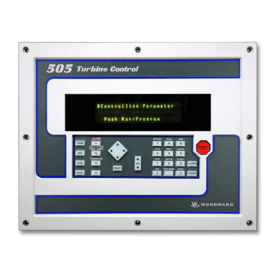
Page 85: Chapter 3. Operator Interface
An overview of the software and information arrangement scheme for the Service Panel is shown in Figure 3-2. SERVICE PANEL The 505E Service Panel operates in several access modes, each of which has a MODES different purpose. These modes are: SERVICE, CONFIGURE, DEBUG, OS_FAULTS, and SYS_INFO. -
Page 86: Software Structure Overview
505E Digital Governor Manual 85018V2 Figure 3-2. Software Structure Overview Woodward... -
Page 87: Using The Service Mode
The DEBUG mode is used to troubleshoot a system during development and is not intended for general use. It should be used only by properly trained Woodward personnel or when expressly authorized by Woodward Governor Company. Entry into the DEBUG mode requires a password. -
Page 88: Header Level
505E Digital Governor Manual 85018V2 Figure 3-3. The Select Mode Level NOTE When entering the mode level, the SERVICE mode will always be the one displayed first in the mode-level message. Header Level The second level is the header level. This level contains the programmable service header blocks as shown in Figure 3-4. -
Page 89: Service Mode
Manual 85018V2 505E Digital Governor Figure 3-5. Block Level Service Mode The SERVICE mode can be used while the engine/turbine is running or shut down. The SERVICE mode permits displaying the value of any SERVICE mode block, and changing the value of any of those blocks that are tuneable. Entry into the SERVICE mode requires a password. -
Page 90: Entering The Service Mode
505E Digital Governor Manual 85018V2 To make direct numeric entries, first bring the displayed value to within 1% of the value to be entered. Press the ENTER key. Press the numerical keys to input the value and press ENTER again. - Page 91 Manual 85018V2 505E Digital Governor NOTE The headers and blocks are assigned their names by the application programmer; this is only an example. 5. The @ indicates which half of the split screen display that key entry will affect. Use the SELECT key to select either the top or bottom of the split screen display.
-
Page 92: Exiting Modes
505E Digital Governor Manual 85018V2 • From header level, to go to a block under a different header, scroll to the new header by using the scroll right (>) or scroll left (<) key, then scroll to the new block by using the scroll down (∨) or scroll up (∧) key. - Page 93 Manual 85018V2 505E Digital Governor CAUTION Entry into the CONFIGURE mode will cause an automatic shutdown of all control outputs. The control will prompt “SHUTDOWN CONTROL? Y/N”. Entering YES will cause all milliamps outputs will go to zero and all relays will de-energize. Entering NO will abort the shutdown.
- Page 94 505E Digital Governor Manual 85018V2 SHUTDOWN CONTROL? Y/N If the NO key is pressed, the system will return to the mode level. If the YES key is pressed, the system will enter the CONFIGURE mode; all control outputs will shut off. The display will show a CONFIGURE mode header. An example is shown below.
-
Page 95: Debug Mode
The DEBUG mode is used to troubleshoot a system during development and is not intended for general use. It should be used only by properly trained Woodward personnel or when expressly authorized by Woodward Governor Company. Entry into the DEBUGmode requires a password. -
Page 96: Os_Faults Mode
505E Digital Governor Manual 85018V2 Figure 3-6. Debug Information Arrangement Pressing the ‘.’ key while in the DEBUG mode will switch the display to the SERVICE mode; pressing the ‘.’ key again will switch the display back to the DEBUG mode. -
Page 97: Os_Faults Mode Information Arrangement
Manual 85018V2 505E Digital Governor Figure 3-7. OS_FAULTS Mode Information Arrangement To Enter the OS_FAULTS mode: 1. The following message will be displayed when the system is at the select mode level. Push < or > for new mode Press ENTER for MMMMMMMM... - Page 98 505E Digital Governor Manual 85018V2 Password OS_FAULTS NOTE For password information see Appendix C at the back of this manual. If the password information is not in this manual, see the supervisor or equipment engineer. 4. Enter the password on the numeric keys and press the ENTER key. The header shown below will be displayed.
-
Page 99: Faults Detected Header
If the display is not going to be used for a while, it is a good idea to return to the Top Level/Root display and permit the system to blank the display to save power and prolong its life. The meanings of the fault messages generated by the 505E System are shown in Chapter 7. Woodward... -
Page 100: Alarms Detected Header
If the display is not going to be used for a while, it is a good idea to return to the Top Level/Root display and permit the system to blank the display to save power and prolong its life. The meanings of the alarm messages generated by the 505E System are shown in Chapter 7. Woodward... -
Page 101: Clear Alarms Detected Header
Manual 85018V2 505E Digital Governor Clear Alarms Detected Header. 1. To clear the alarm list, while the Clear Alarms Detected header is displaying, press the scroll down (∨) key. The following message will be displayed. Clear All Alarms? Y/N 2. To clear the alarm list, press Y (for Yes). The alarm list will be cleared. The following message will appear for one second. -
Page 102: Sys_Info Mode
505E Digital Governor Manual 85018V2 SYS_INFO Mode The SYS_INFO mode displays information about the system. It also permits changing passwords for the different modes and loading a configuration file from a personal computer. The SYS_INFO mode headers are: • System Information — Displays software version and information about the application program. - Page 103 Manual 85018V2 505E Digital Governor To enter the SYS_INFO mode: 1. The following message will be displayed when the system is at the select mode level. Push < or > for new mode Press ENTER for MMMMMMMM (MMMMMMMM = name of mode: SERVICE, CONFIGURE, DEBUG, OS_FAULTS or SYS_INFO) 2.
-
Page 104: System Information Header
505E Digital Governor Manual 85018V2 System Information Header. 1. While the System Information header is displaying, use the scroll down (∨) key to display the system information under it. A message will display as shown below. Clear Alarms Detected This is information about the version being used. -
Page 105: Download Configuration Header
Download Configuration Header. The Download function is to be used only by Woodward certified technicians. 1. While the Download Configuration header is displaying, use the scroll down (∨) key to enter this func tion. A message will display as shown below. - Page 106 505E Digital Governor Manual 85018V2 NOTE For password information, see Appendix D at the back of this manual. If the password information is not in this manual, see the supervisor or equipment engineer. 2. Enter the password on the numeric keys, then press the ENTER key. The system will display the following message.
-
Page 107: Chapter 4 Service Mode Procedures
SERVICE MODE PROCEDURES OVERVIEW The service mode of the 505E control has the same easy to follow format as the program mode. The service mode can be used to customize the control to be more application specific. The parameters that are tuned in the service mode may affect system performance, caution is advised. -
Page 108: The 505E Service Mode
* before it can be adjusted. A work sheet is provided at the end of this manual, to document any changes for future reference. Figure 4-2 illustrates the 505E service menus and the questions/options available under each block. The arrow keys (STEP LEFT, STEP RIGHT) allow you to move right or left across the tops of the function the Service mode columns. - Page 109 Manual 85018V2 505E Digital Governor Figure 4-2. Service Mode Blocks (continued) Woodward...
- Page 110 505E Digital Governor Manual 85018V2 Figure 4-2. Service Mode Blocks (continued) Woodward...
- Page 111 Manual 85018V2 505E Digital Governor Figure 4-2. Service Mode Blocks (continued) Woodward...
- Page 112 505E Digital Governor Manual 85018V2 Figure 4-2. Service Mode Blocks (continued) Woodward...
- Page 113 Manual 85018V2 505E Digital Governor Figure 4-2. Service Mode Blocks (continued) Woodward...
- Page 114 505E Digital Governor Manual 85018V2 Figure 4-2. Service Mode Blocks (continued) Woodward...
- Page 115 Manual 85018V2 505E Digital Governor Figure 4-2. Service Mode Blocks (continued) Woodward...
- Page 116 505E Digital Governor Manual 85018V2 Figure 4-2. Service Mode Blocks (continued) Woodward...
-
Page 117: Service Mode Blocks
Manual 85018V2 505E Digital Governor SERVICE MODE Figure 4-2 shows the 31 service columns/blocks. The actual blocks that appear BLOCKS will vary with the program configuration. To enter the Service Mode, use the procedure described above. To use the Service mode, simply step through the blocks as described above and change the control features for your application. - Page 118 505E Digital Governor Manual 85018V2 Idle/Rated Ramp Settings — change the program or default settings of; idle rated rate; use ramp to idle; idle priority; Sync / Load Share Settings — monitor or change the synchronizing, loadsharing, or sync/load share default settings;...
-
Page 119: Service Mode Worksheet Parameters
Manual 85018V2 505E Digital Governor The service blocks contain information detailing each question and/or 505E program service option. Each question/option shows the default (dflt) value and the adjustable range of that parameter (shown in parentheses). In addition, any additional constraints on the configuration are shown in italics following the description. -
Page 120: Alarm Settings
Set to YES to permanently Hold the changes made to the Setpoint Fast Rate, the Entered Rate, and Underspeed settings. To permanently save these changes into the 505E, set to YES and select the ‘CLEAR’ key twice. Alarm Settings When this header appears in the display, press the down arrow key to view or change this block or press the left or right arrow key to select another block to change. -
Page 121: Speed Control Droop Settings (Only If A Generator Unit)
When set to NO the generator load units are ‘KW’. When YES the units are set to ‘MW’ under the KW/9 key of the 505E front panel. This allows the 505E to display load units in terms of MW as opposed to KW. -
Page 122: Idle / Rated Ramp (Only Displayed If Configured)
HOLD BIAS CHANGES ? dflt= NO (Yes/No) Set to YES to permanently Hold the changes made to the Load Share Gain (%). To permanently save these changes into the 505E, set to YES and select the ‘CLEAR’ key twice. Remote Speed... -
Page 123: Extraction Control Settings
Set to YES to permanently Hold the changes made to the Remote Not Matched Rate and the Maximum and Minimum Speed Settings. To permanently save these changes into the 505E, set to YES and select the ‘CLEAR’ key twice. Extraction SLOW RATE (UNITS/SEC) dflt= xxx (0.01, 1000) -
Page 124: Remote Extr Settings (Only Displayed If Configured)
Set to YES to permanently Hold the changes made to the Setpoint Fast Rate, Entered Rate, Rated Extr Setpoint, and Initial Demand Setting. To permanently save these changes into the 505E, set to YES and select the ‘CLEAR’ key twice. Remote Extr REMOTE NOT MATCHED RATE dflt= xxx (0.01, 1000) -
Page 125: Cascade Control (Only Displayed If Configured)
Set to YES to permanently Hold the changes made to the Remote Not Matched Rate and the Maximum and Minimum Extr Settings. To permanently save these changes into the 505E, set to YES and select the ‘CLEAR’ key twice. Cascade Control... - Page 126 505E Digital Governor Manual 85018V2 RATED CASC SETPT dflt= xxx (--20000, 20000) This setting is only used to determine the cascade control droop. This setpoint is defaulted to the cascade maximum setpoint limit. This value can be changed to a new value, however, the HOLD CHANGES prompt must be set to YES to retain the change.
-
Page 127: Remote Casc Settings (Only Displayed If Configured)
Set to YES to permanently Hold the changes made to the Fast Rate, Entered Rate, Rated Setpt, Casc Not Matched Rate, Maximum Speed Setting and Minimum Speed Setting. To permanently save these changes into the 505E, set to YES and select the ‘CLEAR’ key twice. -
Page 128: Aux Control Settings (Only Displayed If Configured)
Set to YES to permanently Hold the changes made to the Remote Not Matched Rate and the Maximum and Minimum Casc Settings. To permanently save these changes into the 505E, set to YES and select the ‘CLEAR’ key twice. Aux Control... -
Page 129: Remote Aux Settings (Only Displayed If Configured)
NO (Yes/No) Set to YES to permanently Hold the changes made to the Setpoint Fast Rate, Entered Rate, and Rated Aux Setpoint. To permanently save these changes into the 505E, set to YES and select the ‘CLEAR’ key twice. -
Page 130: Breaker Logic (Only Displayed If A Generator)
505E Digital Governor Manual 85018V2 Breaker Logic When this header appears in the display, press the down arrow key to view or (Only Displayed If change this block or press the left or right arrow key to select another block to A Generator) change. -
Page 131: Valve Limiter Settings
NO (Yes/No) Set to YES to permanently Hold the changes made to the Gen Breaker Open Setpoint and Min Load Bias. To permanently save these changes into the 505E, set to YES and select the ‘CLEAR’ key twice. Valve Limiter HP LMTR RATE (%/SEC) dflt= xxx (0.1, 25) -
Page 132: Local / Remote Functions (Only Displayed If Configured)
505E Digital Governor Manual 85018V2 Local / Remote When this header appears in the display, press the down arrow key to view or Functions (Only change this block or press the left or right arrow key to select another block to Displayed If change. -
Page 133: Monitor Relay Outputs
Manual 85018V2 505E Digital Governor CONT IN #3 CLOSED ? (status indication only) CONT IN #4 CLOSED ? (status indication only) CONT IN #5 CLOSED ? (status indication only) CONT IN #6 CLOSED ? (status indication only) CONT IN #7 CLOSED ? -
Page 134: Monitor Speed Inputs
505E Digital Governor Manual 85018V2 TURN ON LEDs ? dflt= NO (Yes/No) When set to YES, turns on all front-panel LEDs to test them. LED ON STATUS ? (status indication only) Monitor Speed When this header appears in the display, press the down arrow key to view or... -
Page 135: Monitor Analog Outputs
Manual 85018V2 505E Digital Governor Monitor Analog When this header appears in the display, press the down arrow key to view or Outputs change this block or press the left or right arrow key to select another block to change. - Page 136 505E Digital Governor Manual 85018V2 X-3 VALUE dflt= 20.0 (-5, 110) Input point #3 of the actuator linearization curve, in percentage. (Must be between the ‘X-2 Value’ and the ‘X-4 Value’ settings) Y-3 VALUE dflt= 20.0 (-5, 110) Output point #3 of the actuator linearization curve, in percentage.
-
Page 137: Act2 Linearization
Manual 85018V2 505E Digital Governor Y-11 VALUE dflt= 100.0 (-5, 110) Output point #11 of the actuator linearization curve, in percentage. ACT1 DEMAND (%) = (status indication only) Displays the actuator demand (%) before the linearization curve. ACT1 OUTPUT (%) = (status indication only) Displays the actuator demand (%) after the linearization curve. -
Page 138: Steam Map Test (Only Displayed If Shut Down)
ENABLE MAP TEST? dflt= NO (Yes/No) (Only Displayed If Set to YES to allow testing of the 505E’s internal steam map constants and limiters. Shut Down) Only active when the ‘Map Test Enabled’ value on the next screen is true. To be active, the unit must be shut down and the turbine speed less than 1000 rpm. -
Page 139: Steam Map Constants
Manual 85018V2 505E Digital Governor LP MAX PRS PRIORITY? dflt= NO (Yes/No) Set to YES to test the steam map using pressure priority for the LP Maximum Limiter. Set to NO for speed priority on this limiter. This setting is only used during this test, the control will use the priority programmed and only when the permissives are met for that priority. -
Page 140: Port 1 Settings (Only Displayed If Configured)
HOLD MAP CHANGES? dflt= NO (Yes/No) Set to YES to Hold the changes made to the K1-K6 Steam Map Constants. To permanently save these changes into the 505E, set to YES and select the ‘CLEAR’ key twice. Port 1 Settings... -
Page 141: Comm Analog Scaling (If Communications Is Used)
Manual 85018V2 505E Digital Governor ERROR CODE (status indication only) Displays the error code related to the communication problem. 0 = No Errors 1 = Illegal Function 2 = Illegal Data Address 3 = Illegal Data Value 9 = Checksum Error 10= Garbled Message Press RESET to clear the port error. -
Page 142: Port Configurations
505E Digital Governor Manual 85018V2 EXTRACTION SCALING FACTOR dflt= 1.0 (1.0, 100) Multiplier constant for all Extraction analog values sent over both Modbus links. When set to a value other than one (1.0), allows the Modbus device to scale inputs that are too small or to allow decimal places to be displayed. - Page 143 Manual 85018V2 505E Digital Governor TIME-OUT DELAY (SEC) dflt= 10.0 (0, 100) Sets the delay for no communication on the Modbus link before the link is considered failed and issues an alarm. PC PORT SETTINGS STATUS (status indication only) Indicates a hardware communications problem.
- Page 144 505E Digital Governor Manual 85018V2 Woodward...
-
Page 145: Chapter 5 Understanding Pid Settings
They correspond to the P (proportional), I (integral), and D (derivative) terms, and are displayed by the 505E as follows: P = Proportional gain (%) -
Page 146: Proportional Response
From The Error. If There Is No Error, Then There Is No Proportional Effect. Integral Integral Gain as stated in the Woodward controls is repeats per minute (or Reset Response Rate). Therefore, a high amount of Integral gain (high number) would result in a large amount of Reset action. -
Page 147: Open Loop Proportional And Integral Response
Manual 85018V2 505E Digital Governor Figure 5-2. Open Loop Proportional and Integral Response Integral response is provided to eliminate the offset that resulted from straight Proportional control. Figure 5-2 shows how the controller action is Proportional to the measurement change, but as we saw earlier, this results in offset. The Integral (or Reset) action is a function of both time and magnitude of the deviation. -
Page 148: Proportional + Integral (Closed Loop)
505E Digital Governor Manual 85018V2 PROPORTIONAL Figure 5-3 shows the closed loop effects of integral action. The bottom curve + INTEGRAL displays the load change. The next curve up shows the setpoint and the measured (CLOSED LOOP) variable, temperature. With the load change the temperature droops or deviates from the setpoint. -
Page 149: Derivative Response
Proportional action to reduce stabilization time in returning the process to the setpoint after an upset. Derivative will not remove offset. Woodward Derivative is split into two working domains, Input dominant and Feedback dominant. The allowed values for DR range from 0.01 to 100. The most common derivative is Feedback dominant, it is automatically selected with an Derivative Ratio (DR) from 1 to 100. -
Page 150: Proportional + Derivative (Closed Loop)
505E Digital Governor Manual 85018V2 Feedback dominant applies the derivative action to the integrator feedback term of the PID equation and is more stable than input dominant derivative. This will not take corrective action as early and it will be less noise sensitive. When tuning the derivative, the DR will be established in the 1 to 100 range because it is easier to tune and more forgiving of excessive values. -
Page 151: Derivative (Effects Of Settings)
Manual 85018V2 505E Digital Governor Figure 5-5 shows how Derivative acts to oppose a change in process in either direction. The dashed line shows the Derivative action going through zero to oppose the process deviation traveling toward zero. Notice offset still exists between the desired setpoint and the drooped control point that resulted from the load change. -
Page 152: Proportional + Integral + Derivative (Closed Loop)
505E Digital Governor Manual 85018V2 PROPORTIONAL Figure 5-7 shows the relationship of valve position to the interaction of the PID + INTEGRAL + modes of control whenever a load change takes place in closed loop. As the DERIVATIVE temperature drops due to the load change, the proportional action moves the (CLOSED LOOP) control valve proportionately to the measurement (temperature) change. -
Page 153: Adding Derivative
The value of the Derivative Ratio (DR) term can range from 0.01 to 100. In order to simplify adjustment of the dynamics of the 505E, adjusting the integral gain value sets both the I and D terms of the PID controller. The DR term establishes the degree of effect the integral gain value has on the “D”... -
Page 154: Tuning Example
1 second reduce the Integral gain term (proportional gain may need to be increased also). On an initial startup with the 505E, all PID dynamic gain terms will require adjustment to match the respective PID’s response to that of its control loop. - Page 155 Manual 85018V2 505E Digital Governor The following method can be used to achieve PID gain values that are close to optimum: 1. Increase Derivative Ratio (DR) to 100 (Service Mode adjustment) 2. Reduce integral gain to 0.01 (Run Mode adjustment) 3.
- Page 156 505E Digital Governor Manual 85018V2 Woodward...
-
Page 157: Chapter 6. Hardware/Operating System Faults
GENERAL Most 505E problems which will be encountered are covered in the manual. Use the table of contents to locate the sections of the manual that may describe a specific problem. Refer to the CONTROLLING PARAM DISPLAYS and ALARM DISPLAYS sections of this manual for display descriptions and corrective actions. -
Page 158: On-Line Diagnostics
505E Digital Governor Manual 85018V2 “Reset caused by” “HALT MONITOR” “Reset caused by” “LOSS OF CLOCK” “Reset caused by” “SOFTWARE RESET” “Reset caused by” “TEST SUBMODULE RESET” All the above errors indicate a problem with the CPU module except the “Display Test Failed”... -
Page 159: Operation Errors And Faults
GND terminal (11) with input wiring disconnected, replace the 505E. The operation of a contact input to the 505E can be checked by verifying that the voltage from the contact input’s (+) terminal measures 24 Vdc with respect to the contact input GND, terminal (11), when the external contact is closed. -
Page 160: Control Adjustments
If an actuator hunts, or appears sticky, it may need dither (especially TM type). If the 505E control is not able to fully close or open the governor valves, check to make sure that the actuators are calibrated correctly, and valve linkage is correctly set. -
Page 161: Appendix A 505E Design Specifications
Manual 85018V2 505E Digital Governor APPENDIX A 505E DESIGN SPECIFICATIONS Woodward... - Page 162 505E Digital Governor Manual 85018V2 Woodward...
-
Page 163: Hardware Specifications
Manual 85018V2 505E Digital Governor HARDWARE AREA CLASSIFICATION SPECIFICATIONS Hazardous environments: Per NEC article 500 Class 1 Division 2 groups A,B,C,D Temperature Code T4 (TBD) PACKAGE Flush mount package Approximate physical size of 11” x 14” x 4” Environmental Category: Lloyd’s Type ENV2... - Page 164 505E Digital Governor Manual 85018V2 OPERATING TEMPERATURE Without Enclosure (8923-439) = -25°C to +65°C, still air, no external heat loads. Passes Lloyd’s type ENV3 Dry Heat test With Enclosure (8923-439) -20°C to +60°C, still air, no external heat loads. Passes Lloyd’s type ENV3 Dry Heat...
-
Page 165: General I/O Specifications
Manual 85018V2 505E Digital Governor GENERAL I/O ANALOG INPUTS SPECIFICATIONS 1. Six 4-20 mA inputs a. One isolated input (input #6). b. Five non-isolated differential inputs or may use 24V provided with single common. 2. 16 Bit resolution over 0-25 mA full-scale range. - Page 166 2. Isolated +24V power provided for discrete inputs. 3. 2.5 mA draw on each input when contact is closed. 4. 18 - 26Vdc external contact power may be used instead of the 505E’s internal power supply. 5. Solid state relays may be used to drive any discrete input: a.
-
Page 167: Software Specifications
Manual 85018V2 505E Digital Governor MODBUS COMMUNICATIONS PORTS 1. Two isolated Modbus communications ports. 2. Supports RTU and ASCII protocol. 3. Baud rates to 57600. 4. Supports RS-232, RS-422, and RS-485 hardware. 5. Maximum network cable length is 4000 feet (50 feet with RS-232). - Page 168 505E Digital Governor Manual 85018V2 14. Relays: a. Trip Relay: 10 msec b. Alarm Relay: 20 msec c. Configurable Relays: 120 msec 15. Readouts: 40 msec 16. Contact Inputs: a. External Trip & Configurable Inputs: 10 msec b. Reset: 40 msec c.
-
Page 169: Appendix B 505E Service Mode Worksheet
Manual 85018V2 505E Digital Governor APPENDIX B 505E SERVICE MODE WORKSHEET Woodward... - Page 170 505E Digital Governor Manual 85018V2 Woodward...
- Page 171 Manual 85018V2 505E Digital Governor 505E SERVICE MODE WORKSHEET APPLICATION NUMBER_____________________________________ GOVERNOR SERIAL NUMBER________________________________ DATE_________ SPEED CONTROL SETTINGS REMOTE SPEED SETTINGS (if configured) Rate to Min = ______________________ RPM/SEC Not Mtchd Rate = ___________________ RPM/SEC Slow Rate /sec = ___________________ RPM/SEC...
- Page 172 505E Digital Governor Manual 85018V2 REMOTE CASC SETTINGS (if configured) LOCAL / REMOTE FUNCTIONS (if configured) Rmt N Mtchd Rte = _______________ UNITS/SEC Remote Enabled __________________ (status only) Rmt Casc Max Rte = ______________ UNITS/SEC Enable Contacts ______________ Yes ____ No ____...
- Page 173 Manual 85018V2 505E Digital Governor Y-5 Value = ________________________________ MONITOR ANALOG INPUTS Extr/Adm (%) = ___________________ (status only) X-6 Value = ________________________________ Anlg In #2 (%) = __________________ (status only) Y-6 Value = ________________________________ Anlg In #3 (%) = __________________ (status only)
- Page 174 505E Digital Governor Manual 85018V2 S-Dmd Limted (%) =________________(status only) TIME OUT DELAY (SEC) = _____________ P-Dmd Limted (%) =________________(status only) At Map Limit _____________________(status only) PORT 2 SETTINGS K1 ( dHP/dS ) = _____________________________ STATUS _________________ (status only) K2 ( dHP/dP ) = _____________________________...
-
Page 175: Appendix Cpassword Information
Manual 85018V2 505E Digital Governor APPENDIX C PASSWORD INFORMATION Woodward... - Page 176 505E Digital Governor Manual 85018V2 Woodward...
-
Page 177: General
PASSWORD Password SERVICE The password for your control is: 1 1 1 1 Press the keys on the 505E front panel in this sequence followed by ENTER to gain access to the SERVICE mode. DEBUG MODE When the display reads:... -
Page 178: Os_Faults Mode Password
505E Digital Governor Manual 85018V2 Press the keys on the 505E front panel in this sequence followed by ENTER to gain access to the CONFIGURE mode. OS_FAULTS When the display reads: MODE PASSWORD Password OS_FAULTS The password for your control is: 1 1 1 4 Press the keys on the 505E frontpanel in this sequence to gain access to the OS_FAULTS mode. - Page 179 Manual 85018V2 505E Digital Governor Woodward...
- Page 180 Fort Collins CO 80522-1519, USA Please include the manual number from the front cover of this publication. Industrial Controls Woodward Governor Company, PO Box 1519 (1000 East Drake Road), Fort Collins CO 80522-1519, USA Phone (1)(970) 482-5811 • Fax (1)(970) 498-3058 Global Services Woodward Governor Company, PO Box 3800 (3800 North Wilson Avenue), Loveland CO 80539-3800, USA Phone (1)(970) 663-3900 •...
Need help?
Do you have a question about the 505E and is the answer not in the manual?
Questions and answers