Advertisement
Table of Contents
Advertisement
Table of Contents

Related Manuals for Carrier A07051


Summary of Contents for Carrier A07051
-
Page 1: Installation Instructions
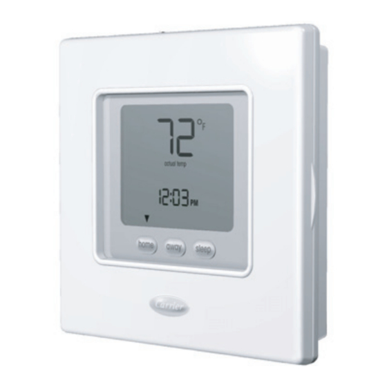
TC---PAC, TC---NAC TC---PHP , TC---NHP Comfortt Series Thermostats Installation Instructions A07051 A07050 Comfort Series Comfort Series Programmable Thermostat Non---Programmable Thermostat NOTE: Read the entire instruction manual before starting the installation. -
Page 3: Table Of Contents
TABLE OF CONTENTS PAGE SAFETY CONSIDERATIONS ........INTRODUCTION . -
Page 4: Introduction
NOTE is used to highlight suggestions which will result in enhanced installation, reliability, or operation. INTRODUCTION Carrier’s Comfortt Series programmable thermostats are wall- -mounted, low- -voltage thermostats which maintain room temperature by controlling the operation of a heating and/or air conditioning system. Both heat pump and air conditioner models are available, each in programmable and non- -programmable versions. -
Page 5: Installation
Power All Comfort Series models are dual powered. They can operate from batteries or 24VAC power. Operation from 24VAC is preferred if available. Battery operation is used when there are not enough wires to support 24VAC operation or when “armchair programming” is desired. For an AC system, 5 wires are needed for 24VAC operation and as few as 2 wires are sufficient for battery operation. -
Page 6: Step 2 - Install Thermostat
In areas with poor air circulation, such as behind a door or in an alcove. Step 2 — Install Thermostat WARNING ELECTRICAL OPERATION HAZARD Failure to follow this warning could result in personal injury or death. Before installing thermostat, turn off all power to equipment. There may be more than 1 power disconnect. - Page 7 CAUTION ENVIRONMENTAL HAZARD Failure to follow this caution may result in environmental damage. Mercury is a hazardous waste. Federal regulations require that Mercury be disposed of properly. 3. Open thermostat (mounting base) to expose mounting holes. The base can be removed to simplify mounting. Press the thumb release at the top of the thermostat and snap apart carefully to separate mounting base from remainder of thermostat.
- Page 8 5. Drill two 3/16- -in. mounting holes in wall where marked. 6. Secure mounting base to wall with 2 anchors and screws provided (additional anchoring holes available for more secure mounting if needed) making sure all wires extend through hole in mounting base. 7.
- Page 9 Rc - 24 VAC, from cooling equipment Rh - 24 VAC, from heating equipment W - Heating C - Common 24 VAC O/B - reversing valve G - Fan Not used Y - Cooling A07159 Fig. 3 - - Terminal Designations CAUTION ELECTRICAL OPERATION HAZARD Failure to follow this caution may result in equipment damage...
-
Page 10: Step 3 - Set Thermostat Configuration
A07157 Fig. 4 - - Attach Comfort Series Programmable Thermostat 11. Close thermostat assembly making sure pins on back of circuit board align with sockets in connector. 12. Turn ON power to unit. When power is applied, all display icons are lit for 2 seconds to test the display. Following this, the equipment type for which the thermostat is configured is displayed for an additional 2 seconds. - Page 11 set by the installer. (Only those marked with an asterisk * below are available to the homeowner.) Following is a list of the options available, an explanation of their function, and their factory default settings. Not all numbers are used in the Comfort Series because not all options are available in this series - - and numbering is consistent across the TB, TC, and TP thermostat lines.
- Page 12 To Enter the Configuration Mode: Press and hold the FAN key for about 10 seconds until the display changes so that only two pairs of digits are showing. The left (programmable version) or the large upper (non- -programmable version) display shows the configuration number right (programmable...
- Page 13 C operates a cool only system: outdoor AC unit with an indoor fan coil; no strip heater support. Note that this option allows a HP thermostat to be converted to control an AC system. Option 03 - - Fahrenheit/Centigrade Selections: F = Fahrenheit —...
- Page 14 Option 10 - - Reversing valve This selection is only available on heat pump systems. “O” terminal can be configured to be energized in either heating mode or in cooling mode, depending on heat pump operation. “O” is used to describe a heat pump system that energizes its reversing valve in cooling.
- Page 15 Option 13 - - Room Air Temperature Offset Selections: - -5 to 5_ F — Default is 0. This option selects the number of degrees F to be added to the displayed temperature to calibrate or deliberately miscalibrate the measured room temperature.
- Page 16 times can reduce the amount of auxiliary heat used. Not available with AC thermostats. Option 18 - - Backlight Configuration Selections: ON, OF — Default is OF. When ON is selected and the thermostat is not battery operated a low level continuous display backlight is always on.
- Page 17 Selecting 2 allows 2 programming periods, P1 and P2, per day. Selecting 4 allows periods P1, P2 , P3, and P4. Not available with non- -programmable thermostats. Option 26 - - Minimum Cooling Setpoint Selections: 52_ to 90_ — Default is 52_F. Sets the lowest cooling setpoint available to the user.
-
Page 18: Step 4 - Check Thermostat Operation
Step 4 — Check Thermostat Operation The Comfort Series thermostats have a built- -in installer test capability. Use it to check thermostat and equipment operation without delays or setpoint adjustments to force heating or cooling. To enter the Installer Test mode, use the same process as is used to enter Installer Configuration, only hold the FAN key longer. -
Page 19: Features And Accessories
Checklist 1. Run equipment through several heating and cooling cycles to ensure proper operation. To operate the thermostat in its normal operating mode, consult the Owner’s Manual. 2. If the equipment is to be left in operation, the setpoints, operating mode, and possibly program schedule must be properly selected. - Page 20 Homeowners Guide for details. If batteries are installed and the thermostat is operated from 24VAC power, battery operation will occur only when 24VAC power is not present. The changeover between 24VAC power and battery power is automatic. Display Lighting The display has two levels of lighting, high level and low level. High level lighting comes on for 10 seconds when the door is opened and/or buttons are being pressed with 24VAC and with batteries.
-
Page 21: Operational And Connection Information
complete itself. If, through some wiring error or failure in the HP, the signal on the O line remains for longer than 15 minutes, the thermostat ignores it and allows Y to be turned off when it is satisfied. If the B function is selected (using Option 10), the thermostat cannot sense when a defrost occurs. -
Page 22: Error Codes
Five- -Minute Compressor Timeguard This timer prevents the compressor from starting unless it has been off for 5 minutes. It can be defeated for one cycle by simultaneously pressing the FAN and UP keys. Minimum On Timer Once the equipment has been turned on, it must remain on for 3 minutes. A change in mode or setpoint will cancel this timer. - Page 23 Table 1 – Outputs EQUIPMENT THERMOSTAT COOL HEAT HEAT CONFIGURATION FACTORY EM HEAT STAGE 1 STAGE 1 STAGE 2 OPTION #1 CONFIGURATION AC, PC AC, HP Y, G --- --- --- --- HP , PH Y, G, O/B Y, G Y, G, W RVS = C HP , PH...
-
Page 24: Wiring Diagrams
WIRING DIAGRAMS A06482 Fig. 5 - - A/C Thermostat Typical Installation A06483 Fig. 6 - - HP Thermostat Typical Installation... -
Page 25: Thermostat Configuration Record
THERMOSTAT CONFIGURATION RECORD Installer Model Number Date _________________________ ______________________________ _________________________ A. Hardware Configuration __________ Seal Hole In Wall B. Mode Settings __________ Mode (Off, Heat, Cool, Auto, Em Heat) __________ Heating Setpoint Value __________ Cooling Setpoint Value __________ Fan (Auto or On) C. - Page 26 E. Configuration Options Option 01 ____ Equipment Type Option 03* ____ Fahrenheit/Centigrade Selection Option 04 ____ Fan (G) on with W/W1 Selection Option 07 ____ Zoning Option 10 ____ Reversing Valve Option 11 ____ Minimum Deadband Between Heating and Cooling Setpoints Option 12 ____ Smart Recovery (programmable models only)
- Page 28 Copyright 2007 Carrier Corp. S 7310 W. Morris St. S Indianapolis, IN 46231 Printed in U.S.A. Edition Date: 02/07 Catalog No: TC ---PAC ---1SI Manufacturer reserves the right to change, at any time, specifications Replaces: NEW and designs without notice and without obligations.
Need help?
Do you have a question about the A07051 and is the answer not in the manual?
Questions and answers