Advertisement
Available languages
Available languages
Quick Links
CITOFONIA • VIDEOCITOFONIA • TVCC • TELEFONIA
MANUALE ISTRUZIONE
CARATTERISTICHE DI FUNZIONAMENTO E INSTALLAZIONE
INSTRUCTIONS MANUAL
OPERATION FEATURES AND INSTALLATION
CITOFONIA • VIDEOCITOFONIA • TVCC • TELEFONIA
BITRON VIDEO s.r.l.
Via Torino 21/B - 10044 PIANEZZA (Torino) Italy
cod. 012175570.10
Tel. +39 011 968.46.11 (r.a.) - Fax +39 011 966.31.49
http://www.bitronvideo.com
e-mail : info@bitronvideo.com
Advertisement

Subscribe to Our Youtube Channel
Related Manuals for Bitron Video GVM3000


Summary of Contents for Bitron Video GVM3000
- Page 1 CARATTERISTICHE DI FUNZIONAMENTO E INSTALLAZIONE INSTRUCTIONS MANUAL OPERATION FEATURES AND INSTALLATION CITOFONIA • VIDEOCITOFONIA • TVCC • TELEFONIA BITRON VIDEO s.r.l. Via Torino 21/B - 10044 PIANEZZA (Torino) Italy cod. 012175570.10 Tel. +39 011 968.46.11 (r.a.) - Fax +39 011 966.31.49 http://www.bitronvideo.com...
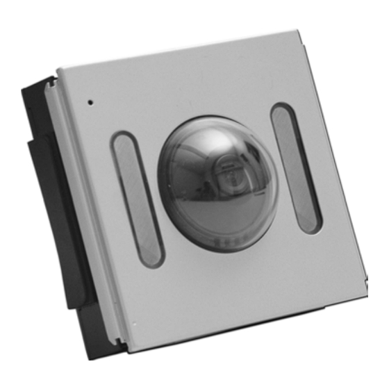
- Page 2 Fig.12 Piastrina di connessione NERA Fig 1 Fig. 13 ( Black ) Connection plate Fig. 11 Modulo Audio Audio Module Piastrina di interruzione grigio/bianco ( grey/white ) Breaker plate Modulo tasti Button module Fig 16 Fig 15 Fig 14 Fig 2 Fig 3 Fig 4 Fig 16a...
- Page 3 - cartongesso…). Tale operazione infatti, sebbene teoricamente possibile, richiederebbe una precisione millimetrica della muratura Sulle basi muro si innestano i moduli funzione (modulo audio GCM3000/0x AV0052/0x, modulo video GVM3000 AV0060, pena l’impossibilità di riuscire a montare moduli e cornici moduli tasti PSM3000/0x ( AV0045/0x ), indicati in fig 1 con la lettera c), inserendoli (dopo aver preventivamente La pulsantiera se correttamente assemblata soddisfa le specifiche IP33 per quanto riguarda l’intrusione di corpi solidi e...
-
Page 4: Caratteristiche Tecniche
1) Generazione del segnale video “bilanciato” trasmettibile senza cavo cassiale. PONTICELLI DI CONFIGURAZIONE 2) illuminazione della scena inquadrata ( infrarossi per GVM3000 AV0060 e luce bianca per GVCM3000 AV0078 ) I dispositivi GVM3000 AV00060 e GVCM3000 AV0078 dispongono di due ponticelli di programmazione che consentono di: 3) Regolazione della posizione della telecamera in fase di installazione per compensare eventuali errori di posizionamento. - Page 5 REGOLAZIONI della pulsantiera stessa. I moduli video GVM3000 e GVCM3000 prevedono le regolazioni sia dell’inclinazione dell’obbiettivo sia del tempo di • Completare l’opera di cablaggio della pulsantiera aggiungendo le piastrine di connessione nere (fornite a corredo dei accensione del monitor.
- Page 6 The “function modules” ( GCM3000/0x AV0052/0x audio module, GVM3000 AV0060 video module, PSM3000/0x negativo alimentazione AV0045/0x buttons modules, indicated with “c” in fig. 1 ) are grafted into the wall support. Upon removing their front covers continua and by turning them slightly as shown in fig.
-
Page 7: Technical Features
Monitors power supply terminal A video module is to be coupled with a GCM3000/2 ( AV00502/2 ) audio module to complete a Bitron Video DOMULAR 3000 This terminal corresponds to the riser wire connecting terminal “3” of monitors. Power supply in not always video doorphone system. - Page 8 • With the jumper in “N” position (default setting), the power supply is timed and present only while the timer is running. In ( “e” in fig. 1) has one only row of pins. As it cannot serve the jumper function that ensures electrical continuity between modules, it is then called “breaker plate”...
-
Page 9: Storage And Handling
WIRES SECTION NOTE For reliable system performance please select you cables in compliance of the following chart: 50 m 100 m 200 m 300 m Dia. Section Dia. Section. Dia. Section Dia. Section Ref. Function Sq. mm Sq. mm Sq. mm Sq. - Page 10 CO LO N N A /RIS ER/CO LO N N E IM PIANTO VID EOC ITO FONIC O (SISTEM A "5FILI") CO N 1 PO STO ESTER NO, 1 CO LONNA CH IAM ATA AL PIANO (R ONZATOR E) "5 w ires" VID EO D O OR PH O NE SYSTEM 12345678 ULTIM A / LA S T / DERN IERE W ITH 1 VISITO R PANEL, 1 R ISER ,...
- Page 11 COLONNA/RISER/COLONNE AN 8419 IMPIANTO VIDEOCITOFONICO (SISTEMA "5FILI") ULTIMA / LAST / DERNIERE ( MV 100 ) CON 2 POSTI ESTERNI, 1 COLONNA AK 7513 ( SD 55 ) segreto auto CHIAMATA AL PIANO (ELETTRONICA) A B 3 1 A B A B A B A B 1234567 8 "5 wires"...
Need help?
Do you have a question about the GVM3000 and is the answer not in the manual?
Questions and answers