Allen-Bradley 1734-IE2C Installation Instructions Manual
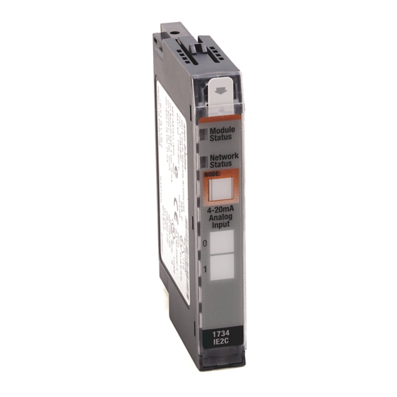
Point i/o 2 current and 2 voltage input
analog modules
Hide thumbs
Also See for 1734-IE2C:
- Installation instructions manual (17 pages) ,
- User manual (221 pages) ,
- Installation instructions manual (24 pages)

Related Manuals for Allen-Bradley 1734-IE2C


Summary of Contents for Allen-Bradley 1734-IE2C
-
Page 1: Table Of Contents
Installation Instructions POINT I/O 2 Current and 2 Voltage Input Analog Modules Catalog numbers 1734-IE2C,1734-IE2V, Series C Table of Contents Topic Page Important User Information Environment and Enclosure Preventing Electrostatic Discharge North American Hazardous Location Approval European Hazardous Location Approval... -
Page 2: Important User Information
2 POINT I/O 2 Current and 2 Voltage Input Analog Modules Important User Information Solid-state equipment has operational characteristics differing from those of electromechanical equipment. Safety Guidelines for the Application, Installation, and Maintenance of Solid-State Controls (Publication SGI-1.1 available from your local Rockwell Automation Sales Office or online at http://www.rockwellautomation.com/literature/) describes some important differences between solid-state equipment and hard-wired electromechanical devices. -
Page 3: Environment And Enclosure
POINT I/O 2 Current and 2 Voltage Input Analog Modules Environment and Enclosure ATTENTION: This equipment is intended for use in a Pollution Degree 2 industrial environment, in overvoltage Category II applications (as defined in IEC publication 60664-1), and at altitudes of up to 2000 m (6562 ft) without derating. This equipment is considered Group 1, Class A industrial equipment according to IEC/CISPR 11. -
Page 4: North American Hazardous Location Approval
4 POINT I/O 2 Current and 2 Voltage Input Analog Modules North American Hazardous Location Approval The following information applies when Informations sur l’utilisation de cet operating this equipment in hazardous équipement en environnements dangereux: locations: Products marked "CL I, DIV 2, GP A, B, C, D" are suitable for Les produits marqués "CL I, DIV 2, GP A, B, C, D"... -
Page 5: European Hazardous Location Approval
POINT I/O 2 Current and 2 Voltage Input Analog Modules European Hazardous Location Approval The following applies when the product bears the Ex Marking This equipment is intended for use in potentially explosive atmospheres as defined by European Union Directive 94/9/EC. DEMKO certifies that this equipment has been found to comply with the Essential Health and Safety Requirements relating to the design and construction of Category 3 equipment intended for use in Zone 2 potentially explosive atmospheres, given in Annex II to this... -
Page 6: Before You Begin
Before You Begin Read this manual for information about how to install the following modules. • 1734-IE2C, Series C, POINT I/O Current Input Analog Module • 1734-IE2V, Series C, POINT I/O Voltage Input Analog Module You can use these Series C POINT I/O™ Input modules with DeviceNet and PROFIBUS adapters. - Page 7 POINT I/O 2 Current and 2 Voltage Input Analog Modules Description Description Module locking mechanism 1734-TB or 1734-TBS mounting base Slide-in writable label Interlocking side pieces Insertable I/O module Mechanical keying (orange) Removable terminal block (RTB) handle DIN rail locking screw (orange) Removable terminal block with screw Module wiring diagram (1734-RTB) or spring clamp (1734-RTBS)
-
Page 8: Install The Mounting Base
8 POINT I/O 2 Current and 2 Voltage Input Analog Modules Install the Mounting Base To install the mounting base on the DIN rail (Allen-Bradley part number 199-DR1; 46277-3; EN50022), proceed as follows: ATTENTION: This product is grounded through the DIN rail to chassis ground. -
Page 9: Install The Module
POINT I/O 2 Current and 2 Voltage Input Analog Modules Install the Module The module can be installed before or after base installation. Make sure that the mounting base is correctly keyed before installing the module into the mounting base. In addition, make sure that the mounting base locking screw is positioned horizontal referenced to the base. -
Page 10: Install The Removable Terminal Block
10 POINT I/O 2 Current and 2 Voltage Input Analog Modules Install the Removable Terminal Block A removable terminal block (RTB) is supplied with your wiring base assembly. To remove, pull up on the RTB handle. This allows the mounting base to be removed and replaced as necessary without removing any of the wirings. - Page 11 POINT I/O 2 Current and 2 Voltage Input Analog Modules WARNING: For 1734-TOPS and 1734-TOP3S, to latch and un-latch the wire, insert a bladed screwdriver (catalog number 1492-N90 – 3 mm diameter) into the opening at approximately 97° (blade surface is parallel with top surface of the opening) and press in (do not push up or down).
-
Page 12: Wire The Module
12 POINT I/O 2 Current and 2 Voltage Input Analog Modules Wire the Module To wire the module, refer to the diagrams and tables. 1734-IE2C 1734-IE2V Module status Module Status Network status Network Status NODE: Analog Voltage Input Status of input 0... - Page 13 POINT I/O 2 Current and 2 Voltage Input Analog Modules POINT I/O 2 Current Input Analog Module Wiring – 1734-IE2C In 0 In 1 Current Current AC or input input device device Chas Chas 4-wire 2-wire In = Input channel,...
-
Page 14: Communicate With The Module
POINT I/O modules send (produce) and receive (consume) I/O data (messages). You map this data into the processor’s memory. The 1734-IE2C and 1734-IE2V modules produce 6 bytes of input data (scanner Rx) and fault status data. The modules do not consume I/O data (scanner Tx). -
Page 15: Interpret Status Indicators
POINT I/O 2 Current and 2 Voltage Input Analog Modules Interpret Status Indicators Refer to the following diagram and table for information on how to interpret the status indicators. 1734-IE2C 1734-IE2V Module status Module Status Network status Network Status NODE:... - Page 16 Channel is being calibrated. Solid red Major channel fault is present. Flashing red Channel is at end of range (0 mA or 21 mA) for 1734-IE2C. Channel is at end of range (over or under) for 1734-IE2V. Publication 1734-IN027C-EN-E - October 2016...
-
Page 17: Specifications
POINT I/O 2 Current and 2 Voltage Input Analog Modules Specifications POINT I/O 2 Current and 2 Voltage Input Analog Modules – 1734-IE2C, 1734-IE2V Attribute 1734-IE2C 1734-IE2V Number of inputs 2 single-ended, non-isolated, 2 single-ended, non-isolated, current voltage Resolution 16 bits – over 0...21 mA 15 bits plus sign 0.32 μA/cnt... - Page 18 18 POINT I/O 2 Current and 2 Voltage Input Analog Modules Includes offset, gain, non-linearity, and repeatability error terms. General Specifications Attribute 1734-IE2C 1734-IE2V Indicators, logic side 1 green/red – module status 1 green/red – network status 2 green/red – input status...
- Page 19 POINT I/O 2 Current and 2 Voltage Input Analog Modules Environmental Specifications Attribute Value Temperature, operating IEC 60068-2-1 (Test Ad, Operating Cold), IEC 60068-2-2 (Test Bd, Operating Dry Heat), IEC 60068-2-14 (Test Nb, Operating Thermal Shock): -20…55 °C (-4…131 °F) Temperature, storage IEC 60068-2-1 (Test Ab, Unpackaged Nonoperating Cold), IEC 60068-2-2 (Test Bb, Unpackaged Nonoperating Dry Heat),...
- Page 20 20 POINT I/O 2 Current and 2 Voltage Input Analog Modules Certifications Certification (when Value product is marked) c-UL-us UL Listed Industrial Control Equipment, certified for US and Canada. See UL File E65584. UL Listed for Class I, Division 2 Group A,B,C,D Hazardous Locations, certified for U.S.
- Page 21 POINT I/O 2 Current and 2 Voltage Input Analog Modules Notes: Publication 1734-IN027C-EN-E - October 2016...
- Page 22 RA-DU002, available at http://www.rockwellautomation.com/literature/. Allen-Bradley, Rockwell Automation, POINT I/O, and TechConnect are trademarks of Rockwell Automation, Inc. Trademarks not belonging to Rockwell Automation are property of their respective companies. Rockwell Automation maintains current product environmental information on its website at http://www.rockwellautomation.com/rockwellautomation/about-us/sustainability-ethics/product-environmental-compliance.page.
Need help?
Do you have a question about the 1734-IE2C and is the answer not in the manual?
Questions and answers