Table of Contents
Advertisement
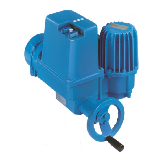
DREHMO
C-matic
Electrical actuator with integral controls
Complementary operating manual for drives with
PROFIBUS DPV0/DPV1 interface
Operating manual
INFORMATION
This operating manual has to be used in conjunction
with the operating manual for actuators (from version 1.15)!
This manual must be kept for future use.
T.-Nr.
186619
Version 1.6
th
Date:
June, 23
2014
Advertisement
Table of Contents

Related Manuals for Drehmo c-matic


Summary of Contents for Drehmo c-matic
- Page 1 DREHMO C-matic Electrical actuator with integral controls Complementary operating manual for drives with PROFIBUS DPV0/DPV1 interface Operating manual T.-Nr. 186619 Version 1.6 Date: June, 23 2014 INFORMATION This operating manual has to be used in conjunction with the operating manual for actuators (from version 1.15)!
- Page 2 Titel DPV1 replaced by DPV0/DPV1 (T-Ste) 2013-10-30 Description of the additional conventional I/O interface (parallel interface) (EE-ScMa) 2014-06-23 Intermediate position 1 and 2 in PPO1 and PPO2, TR11, DIM-10.4 (EE ScMa) Contact Service DREHMO GmbH Tel.: +49 2762 9850-206 Fax: +49 2762 9850-205 E-Mail: drehmo@drehmo.com...
-
Page 3: Table Of Contents
PPO2: (Matic C compatible) .................. 21 Acyclic data ........................22 6 System functions ..............23 Diagnostics........................23 Firmware download ......................23 6.2.1 Required items ......................23 6.2.2 Step by step description ..................23 DREHMO - MaticC Profibus DPV0/DPV1 Page 3 of 28 Complementary operating manual... -
Page 4: Warnings And Notes
1 Warnings and notes 1.1 Standards / directives DREHMO products are designed and manufactured in compliance with recognised standards and directives. This is certified in a declaration of incorporation and a declaration of conformity. The end user or the contractor must ensure that all requirements with respect to assembly, electrical connection, and commissioning at the place of installation are met. - Page 5 The PCB must not be placed on bare metal surfaces or potentially charged surfaces. In case of doubt use a capable ESD pad. Transportation of single PCBs has to be done with ESD suitable packaging to avoid ESD damages. DREHMO - MaticC Profibus DPV0/DPV1 Page 5 of 28 Complementary operating manual...
-
Page 6: Structure Of The Profibus Interface Board
Single ASIC Interface with 1-channel physical media access: Single ASIC Interface with 2-channel physical media access and voter logic: Dual ASIC Interface with 2-channel master/slave redundant physical media access and voter logic: DREHMO - MaticC Profibus DPV0/DPV1 Page 6 of 28 Complementary operating manual... -
Page 7: Electrical Connection
BUS 2 Optional 24V DC A/D inputs input Additionally to the electrical connection enabling/disabling the Profibus termination and the grounding of the shield is done on the connection board. DREHMO - MaticC Profibus DPV0/DPV1 Page 7 of 28 Complementary operating manual... -
Page 8: Bus Cable
0.08 to 0.5 mm²; AWG 28 to 20 Cross section (multi-conductor): 0.08 to 0.5 mm²; AWG 28 to 20 Cross section (multi-conductor): up to 0.25 mm², AWG 28 to 23 (ferrule without plastic shroud allowed) DREHMO - MaticC Profibus DPV0/DPV1 Page 8 of 28 Complementary operating manual... - Page 9 (if a ferrule without plastic shroud is used, due to the commonly ferrule length of approx. 7mm, the conductor isolation doesn’t immerge totally inside the terminal inlet). Picture: PROFIBUS terminals DREHMO - MaticC Profibus DPV0/DPV1 Page 9 of 28 Complementary operating manual...
-
Page 10: Shield Connection
Active conditioning of the fieldbus signals in case of activated termination is only given, if the actuator electronic is powered via the mains power connection or the optional existing external 24V DC supply. DREHMO - MaticC Profibus DPV0/DPV1 Page 10 of 28 Complementary operating manual... -
Page 11: Additional Conventional I/O Interface (Parallel Interface)
The PROFIBUS signals are wired from the actuator housing side towards the compact plug cover side through the intermediate housing via an additional D-Sub connector cable. DREHMO - MaticC Profibus DPV0/DPV1 Page 11 of 28 Complementary operating manual... -
Page 12: Switches / Led's Of The Interface Board
This enables the external watchdog logic. If the jumper is left open the external watchdog logic will be disabled. For normal operation this jumper must be closed. DREHMO - MaticC Profibus DPV0/DPV1 Page 12 of 28 Complementary operating manual... -
Page 13: Dil-Switches
2 to 61 make sense in this case. For the second channel the bit 2 is forced resulting in an address range from 66 to 125 for this channel. Possible address settings: NA) This combination is not permitted. DREHMO - MaticC Profibus DPV0/DPV1 Page 13 of 28 Complementary operating manual... -
Page 14: Dil Switch S4
System redundancy acc. PNO No redundancy; 1 ASIC on channel 1 Spec. 2212 GSD-File: DREM0C27 GSD-File: DREM0C26 ABB redundancy No redundancy; 1 ASIC on channel 1 GSD-File: DREM0C26 GSD-File: DREM0C27 DREHMO - MaticC Profibus DPV0/DPV1 Page 14 of 28 Complementary operating manual... -
Page 15: Diagnosis Led's
If more than one failure is recognized always the failure with the lowest group / code will be signalled. Flash code Fast flash Start of sequence First slow sequence Failure group Second slow sequence Failure code Start Failure group Failure code DREHMO - MaticC Profibus DPV0/DPV1 Page 15 of 28 Complementary operating manual... -
Page 16: Led H13/H23 (Yellow)
Profibus ASIC is in state Reset 2 Pulses Profibus ASIC is in state Passive Idle 3 Pulses Profibus ASIC is in state baud rate detection Profibus ASIC has detected a valid baud rate DREHMO - MaticC Profibus DPV0/DPV1 Page 16 of 28 Complementary operating manual... -
Page 17: Led H15/H25 Profibus Protocol State (Green)
Profibus ASIC is in state Data Exchange. 4.4.7 TEST connector The TEST connector offers extended diagnostic and update possibilities in combination with the DREHMO USB adapter and the PC-Tool Matic C Operator. 5 Profibus Interface 5.1 GSD-Files For device integration into engineering tools different GSD-files are available. The selection of the right GSD file depends on the equipment of the interface board (1 or 2 ASIC’s) and the selected... -
Page 18: Set Parameter Telegram
3 DPV1 bytes. 00 .. 00 34 bytes acc. AUMA GSD The parameter telegram can be extended with a block of 8 bytes for the parameterization by the RedCom layer. DREHMO - MaticC Profibus DPV0/DPV1 Page 18 of 28 Complementary operating manual... -
Page 19: Process Images
Setpoint <0 or > 1000; Multiple commands *) Mode not REMOTE Actuator cannot be controlled by external commands Thermal protection Thermal motor protection tripped Torque OPEN Torque monitoring tripped OPEN DREHMO - MaticC Profibus DPV0/DPV1 Page 19 of 28 Complementary operating manual... - Page 20 (Position controlling according setpoint / actual value comparison) Command STOP Stops the actuator. (Signal has higher priority than (V003) CLOSE and OPEN) Fault acknowledge Reset mechanism for specific tripped faults. (e.g. Torque tripping) *) DREHMO - MaticC Profibus DPV0/DPV1 Page 20 of 28 Complementary operating manual...
-
Page 21: Ppo2: (Matic C Compatible)
Command CLOSE, if AUTO = 0 Command OPEN Command OPEN, if AUTO = 0 4..7 Reserved 0..7 Setpoint position setpoint for position controller (CLOSE = 46 Dez / OPEN = 230 Dez) DREHMO - MaticC Profibus DPV0/DPV1 Page 21 of 28 Complementary operating manual... -
Page 22: Acyclic Data
PLC or DCS system is either done via a DDL (Device Description Language) or a DTM (Device Type Manager). DDL or DTM can be downloaded from the DREHMO homepage or can be ordered free of charge via the DREHMO service. -
Page 23: System Functions
The controller located on the interface board offers the possibility to update the firmware for system treatment or for the implementation of new functionality. 6.2.1 Required items Drehmo USB-Adapter-Kit Test plug SER01 with reset switch (included in Drehmo USB-Adapter-Kit) PC equipped with Windows operating system Programming software Matic C Operator HEX-File with new Firmware 6.2.2 Step by step description... - Page 24 6.) The firmware download wizard will be displayed. The wizard tries to identify the type of the attached target. If the detection fails manually select DMC14 for the device ID. Proceed by clicking OK. DREHMO - MaticC Profibus DPV0/DPV1 Page 24 of 28 Complementary operating manual...
- Page 25 7.) Choose the Hex File containing the binary data for download. A file open dialog can be opened by clicking the button “...”. 8.) By clicking the button Start! the download will be started. DREHMO - MaticC Profibus DPV0/DPV1 Page 25 of 28 Complementary operating manual...
- Page 26 When the download is finished this will be displayed. 12.) Power off the actuator and remove the connection to the PC. 13.) Remove jumper J9 and place it to J8. DREHMO - MaticC Profibus DPV0/DPV1 Page 26 of 28 Complementary operating manual...
- Page 27 Redundancy mode Protocol / Media access 3 Pulses Profibus ASIC is in state WaitCfg. No CheckCfg telegram was Dual ASIC Single ASIC reveived. DREHMO redundancy No redundancy 1 ASIC 4 Pulses Profibus ASIC is in state WaitCfg. A CheckCfg telegram with GSD: DREM0C26 GSD: DREM0C27 invalid configuration was received.
-
Page 28: Drehmo - Maticc Profibus Dpv0/Dpv1
DREHMO GmbH Zum Eichstruck 10 57482 Wenden/Germany Tel.: +49 2762 9850-0 Internet: www.drehmo.com eMail: drehmo@drehmo.com...
Need help?
Do you have a question about the c-matic and is the answer not in the manual?
Questions and answers