Table of Contents
Advertisement
Quick Links
Advertisement
Table of Contents

Related Manuals for Asus X99-E-10G WS


Summary of Contents for Asus X99-E-10G WS
- Page 1 X99-E-10G...
- Page 2 Product warranty or service will not be extended if: (1) the product is repaired, modified or altered, unless such repair, modification of alteration is authorized in writing by ASUS; or (2) the serial number of the product is defaced or missing.
-
Page 3: Table Of Contents
Contents Safety information ..................... vii About this guide ....................... viii Conventions used in this guide ...............ix Typography .....................ix X99-E-10G WS specifications summary..............x Package contents ...................... xv Installation tools and components ................. xvi Chapter 1: Product Introduction Special features..................1-1 1.1.1... - Page 4 Monitor menu ................... 3-52 Boot menu ....................3-59 Tool menu ....................3-64 3.9.1 GPU Post .................. 3-64 3.9.2 ASUS EZ Flash 3 Utility ............3-64 3.9.3 Secure Erase ................3-64 3.9.4 ASUS Overclocking Profile ............3-66 3.9.5 ASUS SPD Information ............. 3-67 3.10...
- Page 5 Chapter 4: Software Support Installing an operating system ..............4-1 Support DVD information ................4-1 4.2.1 Running the support DVD ............4-1 4.2.2 Obtaining the software manuals..........4-2 Software information ................. 4-3 AI Suite 3 ..................... 4-3 4.4.1 Dual Intelligent Processors 5 ............4-7 4.4.2 TPU (Turbo Processing Unit) ............
- Page 6 Installing three SLI-ready graphics cards ........6-8 6.2.4 Installing four SLI-ready graphics cards ........6-9 6.2.5 Installing the device drivers ............6-10 6.2.6 Enabling the NVIDIA technology ........6-10 ® ® Appendix X99-E-10G WS block diagram ................A-1 Notices ........................A-2 ASUS contact information ..................A-7...
-
Page 7: Safety Information
Safety information Electrical safety • To prevent electrical shock hazard, disconnect the power cable from the electrical outlet before relocating the system. • When adding or removing devices to or from the system, ensure that the power cables for the devices are unplugged before the signal cables are connected. If possible, disconnect all power cables from the existing system before you add a device. -
Page 8: About This Guide
Refer to the following sources for additional information and for product and software updates. ASUS website The ASUS website (www.asus.com) provides updated information on ASUS hardware and software products. Optional documentation Your product package may include optional documentation, such as warranty flyers, that may have been added by your dealer. -
Page 9: Conventions Used In This Guide
Conventions used in this guide To make sure that you perform certain tasks properly, take note of the following symbols used throughout this manual. DANGER/WARNING: Information to prevent injury to yourself when trying to complete a task. CAUTION: Information to prevent damage to the components when trying to complete a task. -
Page 10: X99-E-10G Ws Specifications Summary
Extreme Memory Profile (XMP) ® * Hyper DIMM support is subject to the physical characteristics of individual CPUs. Refer to www.asus.com for the memory QVL (Qualified Vendors Lists). 7 x PCI Express 3.0/2.0 x16 Slots (Single at x16, Dual at x16 / x16,... - Page 11 X99-E-10G WS specifications summary Realtek ALC1150 8-channel high definition audio CODEC featuring ® Crystal Sound 3 - Separate layer for left and right track, ensuring both sound deliver equal quality - Top notch audio sensation delivers according to the audio...
- Page 12 X99-E-10G WS specifications summary UEFI BIOS - Most Advanced Options with Fast Response Time M.2 and U.2 Onboard - The Latest Transfer Technology with up to 32Gb/s Data-transfer Speeds for M.2 and U.2 Special Memory O.C. Design - Superb Memory O.C. Capability under Full Load by Minimizing...
- Page 13 - 7 PCIe x 16 Slots - ProCool Power Connector Workstation Exclusive - ASUS PIKE SAS upgrade kit (Optional) 2 x USB 3.0/2.0 Connectors Support Additional 4 USB Ports (19- pin) 2 x USB 2.0/1.1 Connectors Support Additional 4 USB Ports 1 x M.2 Socket 3 (for M Key, Type 2260/2280 Devices)
- Page 14 X99-E-10G WS specifications summary 4 x USB 3.0/2.0 Ports (blue) 2 x USB 3.1 Ports (Type A and Type C) 1 x Optical S/PDIF Out Port Rear Panel I/O Ports 1 x COM port header 2 x Intel 10G LAN (BASE-T) Ports...
-
Page 15: Package Contents
Check your motherboard package for the following items 10 x Serial ATA 6 Gb/s cables ASUS X99-E-10G WS motherboard 1 x 3-WAY SLI bridge connector 1 x 2-in-1 ASUS Q-Connector kit 1 x ASUS Q-Shield ® 1 x ASUS SLI... -
Page 16: Installation Tools And Components
Installation tools and components Intel LGA2011-v3 CPU ® Intel LGA2011-v3 compatible CPU Fan ® Phillips (cross) screwdriver SATA hard disk drive PC chassis DIMM 1 bag of screws Power supply unit SATA optical disc drive (optional) Graphics card The tools and components in the table above are not included in the motherboard package. -
Page 17: Chapter 1: Product Introduction
PCI Express 3.0 x4 slot to speed up data transfer up to 32 Gb/s. This helps enhance the performance of your SSD (Solid State Drive) that is dedicated only to the operating system. * Supports PCIe mode only. ASUS X99-E-10G WS... -
Page 18: Other Special Features
The Type-A USB 3.1 port is completely backward compatible with your existing USB devices, and you'll be all set for USB 3.1's breakneck speeds. The Type-C USB 3.1 port is the all new reversible socket for any-way-up convenience. And ASUS-exclusive USB 3.1 Boost technology automatically accelerates USB 3.1 performance even further! 1.1.2... -
Page 19: Motherboard Overview
Before you install or remove any component, ensure that the ATX power supply is switched off or the power cord is detached from the power supply. Failure to do so may cause severe damage to the motherboard, peripherals, or components. ASUS X99-E-10G WS... -
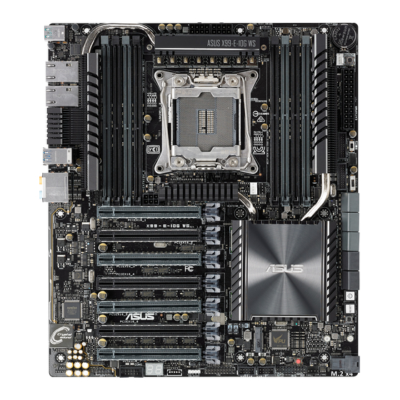
Page 20: Motherboard Layout
1.2.2 Motherboard layout Refer to 1.2.9 Internal connectors and 2.3.1 Rear I/O connection for more information about rear panel connectors and internal connectors. Chapter 1: Product Introduction... -
Page 21: Layout Contents
23. CPU Over Voltage jumper (3-pin CPU_OV) 1-16 24 Q-Code LEDs 1-20 25. Serial port connector (10-1 pin COM) 1-33 26. Digital audio connector (4-1 pin SPDIF_OUT) 1-25 27. Front panel audio connector (10-1 pin AAFP) 1-25 ASUS X99-E-10G WS... -
Page 22: Central Processing Unit (Cpu)
Contact your retailer immediately if the PnP cap is missing, or if you see any damage to the PnP cap/socket contacts/motherboard components. ASUS will shoulder the cost of repair only if the damage is shipment/ transit-related. -
Page 23: System Memory
The motherboard comes with eight (8) DDR 4 (Double Data Rate 4) Quad Inline Memory Modules (DIMM) slots. A DDR4 module is notched differently from a DDR, DDR2, or DDR3 module. DO NOT install a DDR, DDR2, or DDR3 memory module to the DDR4 slot. Recommended memory configurations ASUS X99-E-10G WS... -
Page 24: Memory Configurations
• Hyper DIMM support is subject to the physical characteristics of individual CPUs. Load the X.M.P. or D.O.C.P. settings in the BIOS for the hyper DIMM support. • Visit the ASUS website for the latest QVL. Chapter 1: Product Introduction... -
Page 25: Expansion Slots
Slot No. Slot Description PCIe 3.0/2.0 x16_1 slot PCIe 3.0/2.0 x16_2 slot PCIe 3.0/2.0 x16_3 slot PCIe 3.0/2.0 x16_4 slot PCIe 3.0/2.0 x16_5 slot PCIe 3.0/2.0 x16_6 slot PCIe 3.0/2.0 x16_7 slot ASUS X99-E-10G WS... - Page 26 PCI Express 3.0 operating mode PCIe PCIe PCIe PCIe PCIe PCIe PCIe 3.0/2.0 3.0/2.0 3.0/2.0 3.0/2.0 3.0/2.0 3.0/2.0 3.0/2.0 configuration x16_1 x16_2 x16_3 x16_4 x16_5 x16_6 x16_7 x16 (single Single VGA/ PCIe card recommended) Dual VGA/PCIe cards Triple VGA/ PCIe cards Quad VGA/ PCIe cards Septuple VGA/...
- Page 27 ® Intel EHCI 1 shared – – – – – – – ® Intel EHCI 2 – – – – – shared – – ® HD Audio – – – – – – shared – ASUS X99-E-10G WS 1-11...
-
Page 28: Onboard Buttons And Switches
1.2.6 Onboard buttons and switches Onboard buttons and switches allow you to fine-tune performance when working on a bare or open-case system. This is ideal for overclockers and gamers who continually change settings to enhance system performance. Power-on button (PWR_SW) The motherboard comes with a power-on button that allows you to power up or wake up the system. - Page 29 If the installed DIMMs still fail to boot after the whole tuning process, the DRAM_LED lights continuously. Replace the DIMMs with ones recommended in the Memory QVL (Qualified Vendors Lists) at www.asus.com. • If you turn off the computer and replace DIMMs during the tuning process, the system continues memory tuning after turning on the computer.
- Page 30 Clear CMOS button (CLR_CMOS) Press this button to clear the BIOS setup information only when the systems hangs due to overclocking. EZ XMP switch (EZ_XMP) Enable this switch to overclock the installed DIMMs, allowing you to enhance the DIMM’s speed and performance. The EZ XMP LED (XLED1) lights up when you enable the EZ XMP switch.
- Page 31 CFX switch is enabled. Refer to section 1.2.8 Onboard LEDs for the exact location of the SLI/CFX and PCIE LEDs. • After adjusting PCIE bandwidth in the BIOS, shut down the system for the PCIE LEDs to update the lighting effect. ASUS X99-E-10G WS 1-15...
-
Page 32: Jumpers
1.2.7 Jumpers CPU Over Voltage jumper (3-pin CPU_OV) The CPU Over Voltage jumper allows you to set a higher CPU voltage for a flexible overclocking system, depending on the type of the installed CPU. To gain more CPU voltage setting, insert the jumper to pins 2-3. To go back to its default CPU voltage setting, insert the jumper to pins 1-2. -
Page 33: Onboard Leds
On-Self Test): CPU, VGA card, and hard disk drives. If an error is found, the critical component’s LED stays lit up until the problem is solved. EZ XMP LED (XLED1) This LED lights up when you enable the EZ XMP switch. ASUS X99-E-10G WS 1-17... - Page 34 DRAM LED (DRAM_LED) The DRAM LED checks DRAM during motherboard booting process. If an error is found, the LED flashes until the problem is solved. USB BIOS Flashback LED (FLBK_LED) The BIOS Flashback LED flashes when you press the BIOS Flashback button for BIOS update.
- Page 35 PCIE LEDs The PCIE LEDs light up to indicate which PCIE slots to use when SLI/CFX switch is enabled. SLI/CFX LEDs The SLI/CFX LEDs light up when SLI/CFX switch is enabled. ASUS X99-E-10G WS 1-19...
- Page 36 Q-Code LEDs The Q-Code LED design provides you with a 2-digit error code that displays the system status. Refer to the Q-Code table on the next page for details. Chapter 1: Product Introduction 1-20...
- Page 37 Recovery process started Recovery firmware image is found Recovery firmware image is loaded Reserved for future AMI progress codes F5 – F7 Recovery PPI is not available Recovery capsule is not found (continued on the next page) ASUS X99-E-10G WS 1-21...
- Page 38 Code Description Invalid recovery capsule Reserved for future AMI error codes FB – FF DXE Core is started NVRAM initialization Installation of the PCH Runtime Services CPU DXE initialization is started 63 – 67 PCI host bridge initialization System Agent DXE initialization is started System Agent DXE SMM initialization is started System Agent DXE initialization (System Agent module specific) 6B –...
- Page 39 System is waking up from the S3 sleep state System is waking up from the S4 sleep state System has transitioned into ACPI mode. Interrupt controller is in PIC mode. System has transitioned into ACPI mode. Interrupt controller is in APIC mode. ASUS X99-E-10G WS 1-23...
-
Page 40: Internal Connectors
1.2.9 Internal connectors Intel X99 Serial ATA 6 Gb/s connectors (7-pin SATA6G_12, SATA6G_34, ® SATA6G_56, SATA6G_78, SATA6G_910) These connectors connect to Serial ATA 6 Gb/s hard disk drives via Serial ATA 6 Gb/s signal cables. If you installed Serial ATA hard disk drives, you can create a RAID 0, 1, 5, and 10 configuration with the Intel Rapid Storage Technology through the onboard Intel ®... - Page 41 • If you want to connect a high-definition or an AC’97 front panel audio module to this connector, set the Front Panel Type item in the BIOS setup to [HD] or [AC97]. ASUS X99-E-10G WS 1-25...
- Page 42 USB 3.0 connectors (20-1 pin USB3_E78, USB3_E910) These connectors allow you to connect a USB 3.0 module for additional USB 3.0 front or rear panel ports. With an installed USB 3.0 module, you can enjoy all the benefits of USB 3.0 including faster data transfer speeds of up to 5 Gb/s, faster charging time for USB-chargeable devices, optimized power efficiency, and backward compatibility with USB 2.0.
- Page 43 DO NOT connect a 1394 cable to the USB connectors. Doing so will damage the motherboard! You can connect the front panel USB cable to the ASUS Q-Connector (USB) first, and then install the Q-Connector (USB) to the USB connector onboard if your chassis supports front panel USB ports.
- Page 44 • The CPU_FAN connector supports the CPU fan of maximum 1A (12 W) fan power. • The CPU_FAN and CHA_FAN connectors support the ASUS FAN Xpert 4 feature on X99 platform. • The CPU fan connector detects the type of CPU fan installed and automatically switches the control modes.
- Page 45 • If you want to use two or more high-end PCI Express x16 cards, use a PSU with 1000W power or above to ensure the system stability. ASUS X99-E-10G WS 1-29...
-
Page 46: System Panel Connector
System panel connector (20-8 pin PANEL) This connector supports several chassis-mounted functions. • System power LED (2-pin PLED) This 2-pin connector is for the system power LED. Connect the chassis power LED cable to this connector. The system power LED lights up when you turn on the system power, and blinks when the system is in sleep mode. - Page 47 Connect the button cable that supports DirectKey, from the chassis to this connector on the motherboard. Ensure that your chassis comes with the extra button cable that supports the DirectKey feature. Refer to the technical documentation that came with the chassis for details. ASUS X99-E-10G WS 1-31...
- Page 48 M.2 (Socket 3) This socket allows you to install an M.2 (NGFF) SSD module. • This socket supports PCIe 3.0 x4 M Key design and type 2260/2280 PCIe storage devices. • This socket supports PCIe mode only. • When M.2 is in use, U.2 will be disabled, and when U.2 is in use, M.2 will be disabled. •...
- Page 49 Serial port connector (10-1 pin COM) This connector is for the serial (COM) port. Connect the serial port module cable to one of these connectors, then install the module to a slot opening at the back of the system chassis. ASUS X99-E-10G WS 1-33...
- Page 50 RGB header (4-pin RGB_HEADER) This connector is for RGB LED strips. The RGB header supports 5050 RGB multi-color LED strips (12V/G/R/B), with a maximum power rating of 2A (12V), and no longer than 2 meters. Before you install or remove any component, ensure that the ATX power supply is switched off or the power cord is detached from the power supply.
- Page 51 T_Sensor connector (2-pin T_SENSOR1) This connector is for the thermistor cable that allows you to monitor the temperature of your motherboard’s critical components and connected devices. The thermistor cable is purchased separately. ASUS X99-E-10G WS 1-35...
- Page 52 Chapter 1: Product Introduction 1-36...
-
Page 53: Chapter 2: Basic Installation
2.1.1 Motherboard installation Install the ASUS Q-Shield to the chassis rear I/O panel. Place the motherboard into the chassis, ensuring that its rear I/O ports are aligned to the chassis’ rear I/O panel. - Page 54 Place nine (9) screws into the holes indicated by circles to secure the motherboard to the chassis. DO NOT overtighten the screws! Doing so can damage the motherboard. Chapter 2: Basic Installation...
-
Page 55: Cpu Installation
Please note the order in opening/ closing the double latch. Follow the instructions printed on the metal sealing hatch or the illustrations shown below in this manual. The plastic cap will pop up automatically once the CPU is in place and the hatch properly sealed down. ASUS X99-E-10G WS... - Page 56 Triangle mark Triangle mark Chapter 2: Basic Installation...
-
Page 57: Cpu Heatsink And Fan Assembly Installation
2.1.3 CPU heatsink and fan assembly installation Apply the Thermal Interface Material to the CPU heatsink and CPU before you install the heatsink and fan, if necessary. To install the CPU heatsink and fan assembly ASUS X99-E-10G WS... -
Page 58: Dimm Installation
2.1.4 DIMM installation To remove a DIMM Chapter 2: Basic Installation... -
Page 59: Atx Power Connection
2.1.5 ATX Power connection ASUS X99-E-10G WS... -
Page 60: Sata Device Connection
2.1.6 SATA device connection Chapter 2: Basic Installation... -
Page 61: Front I/O Connector
2.1.7 Front I/O Connector To install ASUS Q-Connector To install USB 2.0 connector To install front panel audio connector AAFP USB 2.0 To install USB 3.0 connector USB 3.0 ASUS X99-E-10G WS... -
Page 62: Expansion Card Installation
2.1.8 Expansion Card installation To install PCIe x16 cards Chapter 2: Basic Installation 2-10... -
Page 63: Bios Update Utility
On your motherboard, press the BIOS Flashback button for three seconds until the Flashback LED blinks three times, indicating that the BIOS Flashback function is enabled. Refer to section 1.2.8 Onboard LEDs for more information of the Flashback LED. If the system fails to boot after flashing the BIOS, unplug the power core and restart the system. ASUS X99-E-10G WS 2-11... - Page 64 BIOS Flashback is not operating properly. This may be caused by improper installation of the USB storage device and filename/file format error. If this scenario happens, please restart the system to turn off the light. • Updating BIOS may have risks. If the BIOS program is damaged during the process and results to the system’s failure to boot up, please contact your local ASUS Service Center. Chapter 2: Basic Installation 2-12...
-
Page 65: Motherboard Rear And Audio Connections
* and **: Refer to the tables on the next page for the LAN port LEDs and audio port definitions. • The plugged USB 3.0 device may run on xHCI mode or EHCI mode, depending on the operating system’s setting. • USB 3.0 devices can only be used as data storage only. • We strongly recommend that you connect USB 3.0 devices to USB 3.0 ports for faster and better performance for your USB 3.0 devices. • Due to the design of the Intel ® X99 series chipset, all USB devices connected to the USB 2.0 and USB 3.0 ports are controlled by the xHCI controller. Some legacy USB devices must update their firmware for better compatibility. ASUS X99-E-10G WS 2-13... - Page 66 * 10G LAN ports LED indications Activity Link LED Speed LED Status Description Status Description ACT/LINK SPEED No link 100 Mbps connection Green Linked Orange 1 Gbps connection Green (Blinking) Data activity Green 10 Gbps connection LAN port You can disable the LAN controllers in BIOS. Due to hardware design, the 10G LAN1 port’s LEDs may continue to blink even when disabled.
-
Page 67: Audio I/O Connections
2.3.2 Audio I/O connections Audio I/O ports Connect to Headphone and Mic Connect to Stereo Speakers ASUS X99-E-10G WS 2-15... - Page 68 Connect to 2.1 channel Speakers Connect to 4.1 channel Speakers Connect to 5.1 channel Speakers Chapter 2: Basic Installation 2-16...
-
Page 69: Starting Up For The First Time
If you do not see anything within 30 seconds from the time you turned on the power, the system may have failed a power-on test. Check the jumper settings and connections or call your retailer for assistance. ASUS X99-E-10G WS 2-17... -
Page 70: Turning Off The Computer
BIOS Beep Description One short beep VGA detected Quick boot set to disabled No keyboard detected One continuous beep followed by two No memory detected short beeps then a pause (repeated) One continuous beep followed by three No VGA detected short beeps One continuous beep followed by four Hardware component failure... -
Page 71: Chapter 3: Bios Setup
BIOS Setup Knowing BIOS The new ASUS UEFI BIOS is a Unified Extensible Interface that complies with UEFI architecture, offering a user-friendly interface that goes beyond the traditional keyboard- only BIOS controls to enable a more flexible and convenient mouse input. You can easily navigate the new UEFI BIOS with the same smoothness as your operating system. -
Page 72: Bios Setup Program
BIOS setup program Use the BIOS Setup to update the BIOS or configure its parameters. The BIOS screen include navigation keys and brief onscreen help to guide you in using the BIOS Setup program. Entering BIOS at startup To enter BIOS Setup at startup, press <Delete> during the Power-On Self Test (POST). If you do not press <Delete>, POST continues with its routines. -
Page 73: Ez Mode
Search on the FAQ Loads optimized Click to display boot devices default settings Selects the boot device priority The boot device options vary depending on the devices you installed to the system. ASUS X99-E-10G WS... -
Page 74: Advanced Mode
3.2.2 Advanced Mode The Advanced Mode provides advanced options for experienced end-users to configure the BIOS settings. The figure below shows an example of the Advanced Mode. Refer to the following sections for the detailed configurations. To switch from EZ Mode to Advanced Mode, click Advanced Mode or press F7 hotkey. Configuration fields Quick Note (F9) Pop-up Menu... -
Page 75: Menu Bar
This button above the menu bar allows you to view and tweak the overclocking settings of your system. It also allows you to change the motherboard’s SATA mode from AHCI to RAID mode. Refer to section 3.2.4 EZ Tuning Wizard for more information. ASUS X99-E-10G WS... -
Page 76: Hot Keys
Move your mouse over this button to show a QR code, scan this QR code on your mobile device to connect to the BIOS FAQ web page of the ASUS support website. You can also scan the following QR code:... -
Page 77: Qfan Control
Click to activate DC Mode configured PWM Mode Select a profile to apply to Click to apply the fan setting your fans Click to undo the Click to go back to main menu changes Select to manually configure your fans ASUS X99-E-10G WS... - Page 78 Configuring fans manually Select Manual from the list of profiles to manually configure your fans’ operating speed. Speed points Select to manually configure your fans To configure your fans: Select the fan that you want to configure and to view its current status. Click and drag the speed points to adjust the fans’...
-
Page 79: Ez Tuning Wizard
To start OC Tuning: Press <F11> on your keyboard or click from the BIOS screen to open EZ Tuning Wizard screen. Click OC then click Next. Select a PC scenario Daily Computing or Gaming/Media Editing, then click Next. ASUS X99-E-10G WS... -
Page 80: Creating Raid
Select a Main Cooling System BOX cooler, Tower cooler, Water cooler, or I’m not sure, then click Next. After selecting the Main Cooling System, click Next then click Yes to start the OC Tuning. Creating RAID To create RAID: Press <F11> on your keyboard or click from the BIOS screen to open EZ Tuning Wizard screen. - Page 81 Speed (RAID 5). After selecting the type of RAID, click Next then click Yes to continue the RAID setup. After the RAID setup is done, click Yes to exit the setup then click OK to reset your system. ASUS X99-E-10G WS 3-11...
-
Page 82: My Favorites
My Favorites My Favorites is your personal space where you can easily save and access your favorite BIOS items. My Favorites comes with several performance, power saving, and fast boot related items by default. You can personalize this screen by adding or removing items. Chapter 3: BIOS Setup 3-12... - Page 83 • Configuration items such as Memory SPD Information, system time and date. Click Exit (ESC) or press <Esc> key to close Setup Tree Map screen. Go to My Favorites menu to view the saved BIOS items. ASUS X99-E-10G WS 3-13...
-
Page 84: Main Menu
Main menu The Main menu screen appears when you enter the Advanced Mode of the BIOS Setup program. The Main menu provides you an overview of the basic system information, and allows you to set the system date, time, language, and security settings. Security The Security menu items allow you to change the system security settings. -
Page 85: Administrator Password
To clear the user password, follow the same steps as in changing a user password, but press <Enter> when prompted to create/confirm the password. After you clear the password, the User Password item on top of the screen shows Not Installed. ASUS X99-E-10G WS 3-15... -
Page 86: Ai Tweaker Menu
Ai Tweaker menu The Ai Tweaker menu items allow you to configure overclocking-related items. Be cautious when changing the settings of the Ai Tweaker menu items. Incorrect field values can cause the system to malfunction. The configuration options for this section vary depending on the CPU and DIMM model you installed on the motherboard. - Page 87 ASUS MultiCore Enhancement [Auto] [Auto] This item allows you to maximize the oveclocking performance optimized by ASUS core ratio settings. [Disabled] This item allows you to set to default core ratio settings. ASUS X99-E-10G WS 3-17...
- Page 88 CPU Core Ratio [By Specific Core] This item allows you to set the CPU core ratio limit per core or synchronize automatically to all cores. Configuration options: [Auto] [Sync All Cores] [By Core Usage] [By Specific Core] When the CPU Core Ratio is set to [Sync All Cores], the following item appears: 1-Core Ratio Limit [Auto] Select [Auto] to apply the CPU default Turbo Ratio setting or manually assign a 1-Core Limit value that must be higher than or equal to the 2-Core...
- Page 89 Configuration options: [Auto] [8] - [33] Max. CPU Cache Ratio [Auto] This item allows you to set the maximum possible CPU cache ratio. Use the <+> and <-> keys to adjust the value. Configuration options: [Auto] [8] - [33] ASUS X99-E-10G WS 3-19...
-
Page 90: Dram Timing Control
Ensure to use water cooling device before selecting [TPU II]. EPU Power Saving Mode [Disabled] The ASUS EPU (Energy Processing Unit) sets the CPU in its minimum power consumption settings. Enable this item to set lower CPU core/cache voltage and achieve the best energy saving condition. - Page 91 DRAM Write Latency [Auto] Configuration options: [Auto] [1] – [31] Third Timings tRRDR [Auto] Configuration options: [Auto] [1] - [7] tRRDD [Auto] Configuration options: [Auto] [1] - [7] tWWDR [Auto] Configuration options: [Auto] [1] - [7] ASUS X99-E-10G WS 3-21...
- Page 92 tWWDD [Auto] Configuration options: [Auto] [1] - [7] tRWDR [Auto] Configuration options: [Auto] [1] - [7] tWRDR [Auto] Configuration options: [Auto] [1] - [7] tWRDD [Auto] Configuration options: [Auto] [1] - [7] tRWSR [Auto] Configuration options: [Auto] [1] - [7] tCCD [Auto] Configuration options: [Auto] [1] - [7] tUWRDR [Auto]...
- Page 93 DRAM IO-L (CHC D0 R1) [Auto] Configuration options: [Auto] [1] - [255] DRAM IO-L (CHC D1 R0) [Auto] Configuration options: [Auto] [1] - [255] DRAM IO-L (CHC D1 R1) [Auto] Configuration options: [Auto] [1] - [255] ASUS X99-E-10G WS 3-23...
- Page 94 DRAM IO-L (CHD D0 R0) [Auto] Configuration options: [Auto] [1] - [255] DRAM IO-L (CHD D0 R1) [Auto] Configuration options: [Auto] [1] - [255] DRAM IO-L (CHD D1 R0) [Auto] Configuration options: [Auto] [1] - [255] DRAM IO-L (CHD D1 R1) [Auto] Configuration options: [Auto] [1] - [255] IO control MC Vref(CHA) [Auto]...
- Page 95 This item allows you to set a DRAM clock period. Configuration options: [Auto] [1] – [19] Memory optimize Control [Auto] This item allows you to optimize the memory control. Configuration options: [Auto] [Disabled] [Enabled] Enhanced Training(CHA/CHB/CHC/CHD) [Auto] Configuration options: [Auto] [Enabled] [Disabled] ASUS X99-E-10G WS 3-25...
- Page 96 DRAM Training MemTest [Auto] This item allows you to enable or disable the memory testing. Configuration options: [Auto] [Disabled] [Enabled] Attempt Fast Boot [Auto] This item allows the portion of the memory reference code to be skipped when possible to increase boot speed. Configuration options: [Auto] [Disabled] [Enabled] Attempt Fast Cold Boot [Auto] This item allows the portion of the memory reference code to be skipped when possible...
- Page 97 DIGI + VRM Duty Control adjusts the current of every VRM phase and the thermal conditions of every phase component. [T. Probe] Select to maintain the VRM thermal balance. [Extreme] Select to maintain the current VRM balance. DO NOT remove the thermal module. The thermal conditions should be monitored. ASUS X99-E-10G WS 3-27...
- Page 98 CPU Current Capability [Auto] This item provides a total power range for CPU overclocking. A higher value setting provides higher power consumption delivery and extends the overclocking frequency range simultaneously. Configuration options: [Auto] [100%] [110%] [120%] [130%] [140%] Configure higher values when overclocking or under a high CPU loading for extra power support.
- Page 99 CPU Integrated VR Efficiency Management [Auto] [Auto] Set to default mode [High Performance] Allow the FIVR (fully integrated voltage regulator) to work at high performance at all times. [Balanced] Improve power saving when the CPU is in a low power state. ASUS X99-E-10G WS 3-29...
- Page 100 Configuration options: [Auto] [0.800] - [2.700]] Fully Manual Mode [Disabled] Enable this item to configure the CPU related voltages. The ASUS-exclusive fully manual mode provides the best voltage adjusting ability. The CPU core, cache, and the system agent voltages can be adjusted separately without the restriction from the CPU.
- Page 101 Additional Turbo Mode CPU Core Voltage [Auto] This item allows you to configure the CPU core voltage offset value. Use the <+> or <-> to adjust the value. The values have an interval of 0.001V. Configuration options: [Auto] [0.001] - [1.920] ASUS X99-E-10G WS 3-31...
- Page 102 CPU Cache Voltage [Auto] Configures the mode of voltage fed to the uncores of the processor. Configuration options: [Auto] [Manual Mode] [Offset Mode] [Adaptive Mode] The following items appear only when you set the CPU Cache Voltage to [Manual Mode]. CPU Cache Voltage Override [Auto] Allows you to configure the CPU cache voltage.
- Page 103 PLL Termination Voltage [Auto] This item allows you to configure the PLL termination voltage. Use the <+> or <-> to adjust the value. The values have an interval of 0.006602V. Configuration options: [Auto] [0.200000] - [1.797684] ASUS X99-E-10G WS 3-33...
- Page 104 PLL Reference Offset Mode Sign [+] Offset the PLL reference value by a positive value. [–] Offset the PLL reference value by a negative value. PLL Reference Offset Value [Auto] This item allows you to configure the amount of voltage fed to the system agent of the CPU including the PCI-E controller and the PCU(power control unit).
-
Page 105: Advanced Menu
The Advanced menu items allow you to change the settings for the CPU and other system devices. Be cautious when changing the settings of the Advanced menu items. Incorrect field values can cause the system to malfunction. ASUS X99-E-10G WS 3-35... -
Page 106: Cpu Configuration
3.6.1 CPU Configuration The items in this menu show the CPU-related information that the BIOS automatically detects. The items in this menu may vary based on the CPU installed. Scroll up or down to display other BIOS items. Hyper-Threading [ALL] [Enabled] This item allows you to enable or disable the Hyper-Threading for logical processor threads. - Page 107 Turbo Mode [Enabled] This item allows you to automatically set the CPU cores to run faster than the base operating frequency when it is below the operating power, current and temperature specification limit. Configuration options: [Disabled] [Enabled] ASUS X99-E-10G WS 3-37...
-
Page 108: Pch Configuration
CPU C-states [Auto] This item allows you to set the power saving of the CPU states. Configuration options: [Auto] [Disabled] [Enabled] The following items appear only when you set the CPU C-states to [Enabled]. Enhanced C1 state [Enabled] This item allows your CPU to reduce power consumption when the system is in idle mode. -
Page 109: Pch Storage Configuration
SATA port. Scroll up or down to display other BIOS items. Hyper kit Mode [Disabled] Disable this option for M.2 devices. Enable this option for “ASUS Hyper kit” card. Configuration options: [Disabled] [Enabled] S.M.A.R.T. Status Check [On] SMART (Self-Monitoring, Analysis and Reporting Technology) is a monitoring system that shows a warning message during POST (Power-On Self Test) when an error occurs in the hard disks. -
Page 110: Sata Controller
The following items appear only when you set the SATA Controller 1 Mode Selection to [RAID] or [AHCI]. Support Aggressive Link Power Management [Disabled] This item is designed for LPM (link power management) support with a better energy saving conditions. When set to [Enabled], the hot plug function of SATA ports are disabled. Configuration options: [Disabled] [Enabled] SATA6G_1(Gray) - SATA6G_6(Gray) SATA6G_1(Gray) - SATA6G_6(Gray) [Enabled]... -
Page 111: System Agent Configuration
The system will automatically select the PCIEX16_1 slot speed. [Gen1] The PCIEX16_1 slot will run at PCI-E 1.0 speed. [Gen2] The PCIEX16_1 slot will run at PCI-E 2.0 speed. [Gen3] The PCIEX16_1 slot will run at PCI-E 3.0 speed. ASUS X99-E-10G WS 3-41... - Page 112 PCIEX16_2 PCIEX16_2 Link Speed [Auto] Allows you to select the operating speed of the PCIEX16_2 speed. Configuration options: [Auto] The system will automatically select the PCIEX16_2 slot speed. [Gen1] The PCIEX16_2 slot will run at PCI-E 1.0 speed. [Gen2] The PCIEX16_2 slot will run at PCI-E 2.0 speed. [Gen3] The PCIEX16_2 slot will run at PCI-E 3.0 speed.
- Page 113 Allows you to enable Virtualization Technology for Directed I/O (VT-d) by reporting the I/O device assignment to VMM through DMAR ACPI tables.. Configuration options: [Enabled] [Disabled] MCTP [Disabled] Configuration options: [Disabled] [Enabled] ACS Control [Disabled] Configuration options: [Disabled] [Enabled] ASUS X99-E-10G WS 3-43...
-
Page 114: Usb Configuration
3.6.5 USB Configuration The items in this menu allow you to change the USB-related features. The Mass Storage Devices item shows the auto-detected values. If no USB device is detected, the item shows None. Intel xHCI Mode [Smart Auto] [Smart Auto] Once the xHCI driver has been detected, the USB 3.0 mode will be supported during both POST and operating system. -
Page 115: Platform Misc Configuration
Configuration options: [Disabled] [L1 Only] PCH - PCI Express PCH DMI ASPM [Disabled] Configuration options: [Disabled] [Enabled] ASPM Support [Disabled] This item is used to enable or disable the ASPM support for all downstream devices. Configuration options: [Disabled] [L1 Only] ASUS X99-E-10G WS 3-45... -
Page 116: Onboard Devices Configuration
3.6.7 Onboard Devices Configuration Scroll up or down to view other BIOS items. HD Audio Controller [Enabled] This item allows you to use the Azalia High Definition Audio Controller Configuration options: [Disabled] [Enabled] The following items appear only when you set the HD Audio Controller to [Enabled]. Front Panel Type [HD Audio] This item allows you to set the front panel audio connector (AAFP) mode to legacy AC’97 or high-definition audio depending on the audio standard that the front panel... -
Page 117: Serial Port Configuration
Intel Lan2 PXE Option ROM [Disabled] This item allows you launch Intel Lan2 PXE OPROM. Configuration options: [Enabled] [Disabled] Serial Port Configuration Serial Port [On] This port allows you to enable or disable Serial Port. Configuration options: [On] [Off] ASUS X99-E-10G WS 3-47... -
Page 118: Apm Configuration
Change Settings [Auto] Allows you to choose the setting for Super IO device. Configuration options: [Auto] [IO=3F8h; IRQ=4] [IO=2F8h; IRQ=3] [IO=3E8h; IRQ=4] [IO=2E8h; IRQ=3] 3.6.8 APM Configuration ErP Ready [Disabled] This item allows you to switch off some power at S4+S5 or S5 to get the system ready for ErP requirement. -
Page 119: Network Stack Configuration
This item allows you to enable/disable the Ipv4/Ipv6 PXE wake event. Configuration options: [Disabled] [Enabled] 3.6.10 HDD/SDD SMART Information This menu displays the SMART information of the connected devices. NVM Express devices do not support SMART information. ASUS X99-E-10G WS 3-49... -
Page 120: Intel(R) Ethernet Controller - 00:1E:99:00:01:1B
3.6.11 Intel(R) Ethernet Controller - 00:1E:99:00:01:1B This menu allows you to configure the parameters of the 10 Gigabit Ethernet device NIC Configuration The items in this menu allow you to configure the boot protocol, Wake-on LAN, link speed, and virtual LAN. Link Speed [Auto Negotiated] This item allows you to specify the port speed used for the selected boot protocol. -
Page 121: Intel(R) Ethernet Controller - 00:1E:99:00:01:1C
Blink LEDs [0] This item allows you to identify the physical network port with the blinking associated LEDs. Use the number keys to key in the number. The values range from 0 to 15. ASUS X99-E-10G WS 3-51... -
Page 122: Monitor Menu
Monitor menu The Monitor menu displays the system temperature/power status, and allows you to change the fan settings. Scroll up or down to view other BIOS items. CPU Temperature, Motherboard Temperature, PCIEX16_1 slot Temperature, PCIEX16_3 slot Temperature, VRM Temperature, PCH Temperature, T_ Sensor1 Temperature [xxx°C/xxx°F] The onboard hardware monitor automatically detects and displays the temperatures. - Page 123 20% to 100%. When the CPU temperature reaches the upper limit, the CPU fan will operate at the maximum duty cycle. CPU Middle Temperature Use the <+> and <-> keys to adjust the CPU middle temperature. The values range from 25°C to 75°C. ASUS X99-E-10G WS 3-53...
- Page 124 For Multiple Sources, select up to three temperature sources and the fan will automatically change based on the highest temperature. • ASUS FAN EXTENSION CARD is required to configure these items. Chassis Fan 1-2 Step Up [0 sec] This item allows you to set the value of the chassis fan step up.
- Page 125 Detect the type of Water Pump installed and automatically switches the mode control. [DC mode] Enable the Water Pump control in DC mode for 3-pin Water Pump. [PWM mode] Enable the Water Pump control in PWM mode for 4-pin Water Pump. ASUS X99-E-10G WS 3-55...
- Page 126 The following items appear only when you set the Water Pump Control to [Auto], [PWM Mode], and [DC Mode]. Water Pump Temperature Use the <+> and <-> keys to adjust the upper limit of the water pump. The values range from 45°C to 75°C. The water pump will operate at the maximum duty cycle when the CPU temperature is higher than the limit.
- Page 127 For Multiple Sources, select up to three temperature sources and the fan will automatically change based on the highest temperature. • ASUS FAN EXTENSION CARD is required to configure these items. HAMP Fan Step Up [0 sec] This item allows you to set the value of the HAMP fan step up.
- Page 128 HAMP Fan Middle. Duty Cycle (%) Use the <+> or <-> keys to adjust the HAMP Fan middle duty cycle. The values range from 60% to 100%. HAMP Fan Lower Temperature Use the <+> or <-> keys to adjust the lower limit of the HAMP Fan temperature.
-
Page 129: Boot Menu
POST time. [Full Initial] All USB devices will be available during POST. This process will extend the POST time. [Partial Initial] For a faster POST time, only USB ports with keyboard and mouse connections will be detected. ASUS X99-E-10G WS 3-59... - Page 130 Network Stack Driver Support [Disabled] [Disabled] Select to skip the network stack driver from loading during POST. [Enabled] Select to load the network stack driver during POST. Redirection Support [Disabled] This item allows you to enable or disable redirection support. Configuration options: [Enabled] [Disabled] Next Boot after AC Power Loss [Normal Boot] [Normal Boot]...
-
Page 131: Secure Boot
Configuration options: [Legacy only] [UEFI driver first] Secure Boot This item allows you to configure the Windows Secure Boot settings and manage its keys to ® protect the system from unauthorized access and malwares during POST. ASUS X99-E-10G WS 3-61... - Page 132 OS Type [Windows UEFI mode] [Windows UEFI Mode] Execute the Microsoft secure boot check. Only check this option when booting on Windows UEFI mode or other Microsoft secure boot compliant operating systems. [Other OS] Select this option to get the optimized functions when booting on Windows non-UEFI mode and Microsoft secure boot noncompliant operating systems.
-
Page 133: Boot Option Priorities
® ® supported). • To select the boot device during system startup, press <F8> when the ASUS Logo appears. Boot Override These items displays the available devices. The number of device items that appears on the screen depends on the number of devices installed in the system. Click an item to start booting from the selected device. -
Page 134: Tool Menu
To launch Secure Erase, click Tool > Secure Erase on the Advanced mode menu. Check the ASUS support site for a full list of SSDs tested with Secure Erase. The drive may become unstable if you run Secure Erase on an incompatible SSD. - Page 135 Locked. SSDs might be locked if the Secure Erase process is either incomplete or was stopped. This may be due to a third party software that uses a different password defined by ASUS. You have to unlock the SSD in the software before proceeding with Secure Erase.
-
Page 136: Asus Overclocking Profile
3.9.4 ASUS Overclocking Profile This item allows you to store or load multiple BIOS settings. Load from Profile This item allows you to load the previous BIOS settings saved in the BIOS Flash. Key in the profile number that saved your BIOS settings, press <Enter>, and then select Yes. -
Page 137: Asus Spd Information
3.9.5 ASUS SPD Information This item allows you to view the DRAM SPD information. ASUS X99-E-10G WS 3-67... -
Page 138: Exit Menu
3.10 Exit menu The Exit menu items allow you to load the optimal default values for the BIOS items, and save or discard your changes to the BIOS items. You can access the EZ Mode from the Exit menu. Load Optimized Defaults This option allows you to load the default values for each of the parameters on the Setup menus. -
Page 139: Updating Bios
® ASUS EZ Flash 3: Updates the BIOS using a USB flash drive. ASUS CrashFree BIOS 3: Restores the BIOS using the motherboard support DVD or a USB flash drive when the BIOS file fails or gets corrupted. 3.11.1... -
Page 140: Asus Ez Flash 3
3.11.2 ASUS EZ Flash 3 ASUS EZ Flash 3 allows you to download and update to the latest BIOS through the Internet without having to use a bootable floppy disk or an OS-based utility. Updating through the Internet varies per region and Internet conditions. Check your local Internet connection before updating through the Internet. - Page 141 To update the BIOS by Internet: Enter the Advanced Mode of the BIOS setup program. Go to the Tool menu to select ASUS EZ Flash Utility and press <Enter>. Select via Internet. Press the Left/Right arrow keys to select an Internet connection method, and then press <Enter>.
-
Page 142: Asus Crashfree Bios 3
The BIOS file in the motherboard support DVD may be older than the BIOS file published on the ASUS official website. If you want to use the newer BIOS file, download the file at https://www.asus.com/support/ and save it to a USB flash drive. -
Page 143: Chapter 4: Software Support
8.1, and ® ® 32-bit/64-bit Windows 10 operating systems (OS). ® • Motherboard settings and hardware options vary. Use the setup procedures presented in this chapter for reference only. Refer to your OS documentation for detailed information. Support DVD information The contents of the support DVD are subject to change at any time without notice. Visit www.asus.com for updates. 4.2.1 Running the support DVD Ensure that you have an Administrator account before running the support DVD in Windows 7, Windows 8.1, or Windows 10 OS. ® ® ® To run the support DVD Place the Support DVD into the optical drive. 2. In the AutoPlay dialog box, click Run ASSETUP.exe. If Autorun is NOT enabled in your computer, browse the contents of the support DVD to locate the file SETUP.EXE from the BIN folder. Double-click the ASSETUP.EXE to run the support DVD. ASUS X99-E-10G WS... -
Page 144: Obtaining The Software Manuals
Click to display free software for you to use Click to select an item to install Click to display the ASUS contact information Click to browse the file list of the support CD Click to install the selected items 4.2.2 Obtaining the software manuals The software manuals are included in the support DVD. Follow the instructions below to get... -
Page 145: Software Information
AI Suite 3 AI Suite 3 is an all-in-one interface that integrates several ASUS utilities and allows you to launch and operate these utilities simultaneously. Installing AI Suite 3 Ensure that you have an Administrator account before installing AI Suite 3 in Windows 7, ® Windows 8.1, or Windows 10 OS. ® ® To install AI Suite 3 on your computer: Windows 7 OS ® Place the Support DVD into the optical drive. 2. In the AutoPlay dialog box, click Run ASSETUP.exe then select the Utilities tab 3. From the Utilities tab, check AI Suite 3 and select Install, then follow the succeeding onscreen instructions. ASUS X99-E-10G WS... - Page 146 If the ASUS motherboard support DVD main menu did not appear, try the following steps: Go to the Start Screen then click the Desktop app. On the lower left corner of the Desktop, click File Explorer then select your DVD drive and double-click the Setup application. Launching AI Suite 3 Windows 7 OS ® From the Desktop, click Start > All Programs > ASUS > AI Suite 3 > AI Suite 3. You can also launch AI Suite 3 in Windows 7 by clicking on the Notification area. ® Windows 8.1 / Windows 10 OS ® ®...
- Page 147 AI Suite 3 Main menu The AI Suite 3 main menu gives you easy-access controls and insight to what’s going on with your computer - allowing you to optimize performance settings while at the same time ensuring system stability. The AI Suite main menu includes is a quick-access menu bar that allows you to swiftly launch any of the integrated ASUS utilities. Click on the left of the menu to launch the menu bar. The AI Suite 3 screenshots in this section are for reference only and can vary depending on motherboard model.. Click to launch AI Suite 3 menu bar AI Suite 3 main menu bar • Some functions in the AI Suite 3 main menu in this user guide may vary depending on the motherboard model. • Refer to the software manual in the support DVD or visit the ASUS website at www.asus.com for detailed software configuration. ASUS X99-E-10G WS...
- Page 148 AI Suite 3 mini-menu The AI Suite 3 mini-menu appears on the desktop and can be conveniently accessed and moved around. The AI Suite 3 mini-menu allows you to quickly access the important items in the AI Suite 3. Click to expand the quick launch area or start quick launch Quick launch area Click to select the available features for AI Suite 3 mini-menu Chapter 4: Software Support...
-
Page 149: Dual Intelligent Processors 5
4.4.1 Dual Intelligent Processors 5 ASUS Dual Intelligent Processors 5 combines TPU, EPU, DIGI+ Power Control, Fan Xpert 4, and Turbo App functions to push the system’s performance to its optimal potential. It automatically balances the system’s performance, power saving, levels, and fan settings via the user-friendly AI Suite 3 utility. 5-Way Optimization The 5-Way Optimization function dynamically optimizes your PC based on real-time usage to provide the best system status. It covers the essential areas such as CPU performance, energy saving, stable digital power, cool and quiet fan control, and includes tailored settings for your apps to ensure your PC is ready for gaming, entertainment, productivity, or just about anything. 5-Way Optimization screen Click or tap this 5-Way Optimization button to auto-detect and tune the best settings for your system DO NOT remove your fan during the tuning process. ASUS X99-E-10G WS... -
Page 150: Tpu (Turbo Processing Unit)
4.4.2 TPU (Turbo Processing Unit) TPU allows you to manually adjust the CPU frequency, core ratio, DRAM frequency, and related voltages for enhanced system stability and performance boost. Refer to the CPU documentation before adjusting CPU voltage settings. Setting a high voltage may damage the CPU permanently and setting a low voltage may lead to an unstable system. For system stability, the TPU settings are not saved in the BIOS and are not loaded during system bootup. Save your overclocking settings as a TPU profile and manually load this profile after system bootup. Launching TPU on your computer To launch TPU, click or tap on the top-right corner of the AI Suite 3 main menu, then select TPU. Using TPU CPU Frequency Click to adjust the Base Click to select the Clock Frequency, CPU Ratio, and number of cores to adjust CPU Cache Ratio Adjust the CPU voltages and... -
Page 151: Turbo App
Click to assign a specific application(.exe) into Turbo App list Click to apply the changes Click to undo the changes Applications list pane Displays all the running applications on your system. Turbo App List pane Displays the applications added to the Turbo App List. Click the icon for more settings. * Only applications on the Turbo App List can be configured. ASUS X99-E-10G WS... -
Page 152: Epu (Energy Processing Unit)
4.4.4 EPU (Energy Processing Unit) EPU is a real-time system power-saving chip that automatically detects the current system load and intelligently moderates power usage. It offers a total system-wide energy optimization, reduces fan noise, and extends the lifespan of your hardware components. Launching EPU on your computer To launch EPU, click or tap on the top-right corner of the AI Suite 3 main menu, then select EPU. Using EPU Click to configure the settings in Max Power Saving mode Click to configure the settings Click to configure the in High Performance mode settings in Away mode Click select a fan... -
Page 153: Fan Xpert 4
Click and drag the sliders to adjust the fan’s responsiveness Click to apply the changes Click to undo Click to switch between the the changes CPU and chassis fan screens The Extreme Quiet Mode allows you to configure the CPU fan speed control range to its extreme low setting when using a PWM CPU fan. ASUS X99-E-10G WS 4-11... -
Page 154: Pc Cleaner
RPM Mode RPM Mode allows you to set the fan speed when the CPU temperature is below 75 Click and drag to adjust the Click to switch between the fan’s speed CPU and chassis fan screens • When the CPU temperature reaches 75 C, the fan will automatically run at full speed to protect the CPU. • The Fan Xpert 4 may not be able to detect the fan speed if your fan is installed with an external control kit for rotation speed. • Fan Xpert 4 does not support 2-pin fans. If you install a 2-pin fan, it can only run at its full speed. • If the CPU or chassis fans have been changed, the Fan Auto Tuning process should be repeated. 4.4.6 PC Cleaner PC Cleaner allows you to clean the system junk files by scanning and deleting selected files. Launching PC Cleaner on your computer To launch PC Cleaner, click or tap on the top-right corner of the AI Suite 3 main menu, then select PC Cleaner. -
Page 155: Digi+ Power Control
CPU Power Phase Control Increase the phase number under a heavy system load to get more transient and better thermal performance. Reduce the phase number under a light system load to increase the VRM efficiency. CPU VRM Switching Frequency Enables spread spectrum to enhance system stability. CPU Load-line Calibration It allows you to adjust the voltage range to control the CPU Load-line. Adjust to a high value for system performance or to a low value for power efficiency. CPU Current Capability CPU Current Capability provides a wider total power range for overclocking. A higher value brings a wider total power range and extends the overclocking frequency range simultaneously. CPU Power Thermal Control A higher temperature brings a wider CPU power thermal range and extends the overclocking tolerance to enlarge the overclocking potential. ASUS X99-E-10G WS 4-13... - Page 156 Click or tap to undo Click or tap to the changes apply the changes DRAM Voltage Frequency Allows you to adjust the DRAM switching frequency to stabilize the system or to increase the overclocking range. DRAM Current Capability A higher value brings a wider total power range and extends the overclocking frequency range simultaneously. DRAM Power Phase Control Select Extreme for full phase mode to increase system performance or select Optimized for ASUS optimized phase tuning profile to increase the DRAM power efficiency. • The actual performance boost may vary depending on your CPU specification. • Ensure that the cooling modules are properly installed in your motherboard to monitor the thermal conditions. Chapter 4: Software Support 4-14...
-
Page 157: Ai Charger
Launching Ai Charger+ on your computer To launch Ai Charger+, click or tap on the top-right corner of the AI Suite 3 main menu, then select Ai Chager+. Ai Charger+ screen Tick to enable or Click to apply the disable Ai Charger+ selection • * Check the manufacturer if your USB device is a Battery Charging Specification 1.1 (BC 1.1) compliant or compatible device. • ** Actual charging speeds may vary depending on the charging rate and specifications of your USB device. • To ensure normal charging function, disconnect and reconnect your USB device every time you enable or disable Ai Charger+. • Ai Charger+ does not support USB hubs, USB extension cables, and generic USB cables. ASUS X99-E-10G WS 4-15... -
Page 158: Usb 3.1 Boost
Click to enable the USB device’s normal data transfer rate Click to select a USB device Ensure to connect your USB 3.0 or 3.1 device to the USB ports that support USB 3.1 Boost. Refer to 2.3.1 Rear I/O connection section for more details. • USB 3.1 Boost automatically detects the USB devices that support UASP. For a list of UASP-supported USB devices, visit the ASUS website at www.asus.com. • The data transfer speed varies with USB devices. For a higher data transfer performance, use a USB 3.1 device. Chapter 4: Software Support 4-16... -
Page 159: Ez Update
To launch EZ Update, click or tap on the top-right corner of the AI Suite 3 main menu, then select EZ Update. EZ Update screen Click to automatically update your motherboard’s driver, software and firmware Click to select a Click to update boot logo the BIOS Click to search and select the BIOS file ASUS X99-E-10G WS 4-17... -
Page 160: System Information
4.4.11 System Information This utility displays the detailed information and settings of the installed motherboard, CPU, and memory. Launching System Information on your computer To launch System Information, click or tap on the top-right corner of the AI Suite 3 main menu, then select System Information. Viewing the motherboard information Click the MB tab to view the motherboard’s information. Viewing the CPU information Click the CPU tab to view the processor’s information. Chapter 4: Software Support 4-18... -
Page 161: Mobo Connect
Viewing the SPD information Click the SPD tab to view the memory’s information. 4.4.12 Mobo Connect Mobo Connect allows you to share the PC’s keyboard/mouse for smart devices, or stream audio playback from your smart device yo the PC. Launching Mobo Connect on your computer To launch Mobo Connect, click or tap on the top-right corner of the AI Suite 3 main menu, then select Mobo Connect. Mobo Connect screen Set Hotkey for Keyboard/ Mouse sharing Select device for Keyboard/Mouse sharing Click to apply the settings ASUS X99-E-10G WS 4-19... -
Page 162: Usb Bios Flashback
4.4.13 USB BIOS Flashback USB BIOS Flashback allows you to check and save the latest BIOS version to a USB storage device. Use this utility to quickly check for the latest available BIOS and set the BIOS download schedule. Launching USB BIOS Flashback on your computer To launch USB BIOS Flashback, click or tap on the top-right corner of the AI Suite 3 main menu, then select USB BIOS Flashback. USB BIOS Flashback is available only in selected motherboard models. Using USB BIOS Flashback Set a schedule for the BIOS Update download Click to cancel the download schedule setting Click to apply the download Click to check for a new BIOS update schedule setting available for download... - Page 163 Downloading the latest BIOS Before you start downloading, ensure that you have installed the USB storage device to your computer’s USB port that supports USB BIOS Flashback. Refer to section 2.3.1 Rear I/O connection of this user guide for more details. To download the updated BIOS: From the USB BIOS Flashback screen, Click Check for New BIOS Update. Wait for the system to check the latest BIOS version. After the utility detects a new BIOS, Click from the Save to: field, select the USB flash drive, then Click Download. After the download is complete, Click OK. ASUS X99-E-10G WS 4-21...
-
Page 164: Push Notice
4.4.14 Push Notice This utility allows you get the detailed status of your system to your smart device. You can also send messages to your smart device using this utility. Before using this utility, ensure that you pair your computer with your smart device. For pairing information, refer to section Pairing your computer and smart device. Launching Push Notice on your computer To launch Push Notice, click or tap on the top-right corner of the AI Suite 3 main menu, then select Push Notice. Push Notice screen Click or tap to enable Push Notice Tick to select the smart device Click or tap to Click or tap to apply the settings discard the settings... - Page 165 Setting up PC Status alerts This feature allows you to send alerts of the unusual activities of the voltage, temperature, and fan settings of your computer to your smart device. Tick to select the smart device Tick to select and send alerts to your smart device Tick to send alert when the components selected are back to its normal status ASUS X99-E-10G WS 4-23...
- Page 166 Sending messages to your smart device This feature allows you to send messages to your smart device. You can also send messages via the Push Notice messaging shortcut on the lower-right corner of your screen. To do this, click or tap << then click or tap then select Tick to select the smart device Click or tap to send your message Click or tap to key in your message Viewing your computer status on your smart device Tap on your smart device to launch Push Notice.
-
Page 167: Audio Configurations
HD Audio Manager with DTS Studio Sound ® Windows 10 / Windows 8.1 / Windows ® ® ® Configuration option tabs (vary with the audio devices connected) Advanced settings Set default device button Control settings panel Analog and digital connector status ASUS X99-E-10G WS 4-25... - Page 168 Selecting an audio output Realtek HD Audio Manager allows you to select the type of audio output depending on the output device that you are using. To select an audio output: Insert the audio device’s jack to the Line Out (lime) port. If the audio device’s jack is already inserted to the corresponding port, Click on the Realtek HD Audio Manager. On the pop-up window, tick the audio device that you plugged to the Line Out port then Click Next. If you select Headphone, Click to select the type of headphone installed then Click OK. If you select Front Speaker Out, Click to select the type of speaker installed then Click OK. Chapter 4: Software Support 4-26...
-
Page 169: Chapter 5: Raid Support
With the RAID 10 configuration you get all the benefits of both RAID 0 and RAID 1 configurations. Use four new hard disk drives or use an existing drive and three new drives for this setup. ASUS X99-E-10G WS... -
Page 170: Installing Serial Ata Hard Disks
5.1.2 Installing Serial ATA hard disks The motherboard supports Serial ATA hard disk drives. For optimal performance, install identical drives of the same model and capacity when creating a disk array. To install the SATA hard disks for a RAID configuration: Install the SATA hard disks into the drive bays. -
Page 171: Intel ® Rapid Storage Technology Option Rom Utility
The RAID BIOS setup screens shown in this section are for reference only and may not exactly match the items on your screen. The utility supports maximum four hard disk drives for RAID configuration. ASUS X99-E-10G WS... - Page 172 Creating a RAID set To create a RAID set: From the utility main menu, select 1. Create RAID Volume and press <Enter>. The following screen appears: Name: Volume 0 RAID Level: aaaaaaaaaaaaaaa Disks: dssdsdsds Strip Size:aaaaaaaaaaaaaaaa Capacity:aaaaaaaaaaaaaa Sync:aaaaaaaaaa Create volume [HELP] Enter a unique volume name that has no special characters and is 16 characters or less.
- Page 173 ALL DATA ON SELECTED DISKS WILL BE LOST. Are you sure you want to create this volume? (Y/N) Press <Y> to create the RAID volume and return to the main menu, or <N> to go back to the CREATE VOLUME menu. ASUS X99-E-10G WS...
- Page 174 Deleting a RAID set Be cautious when deleting a RAID set. You will lose all data on the hard disk drives when you delete a RAID set. To delete a RAID set: From the utility main menu, select 2. Delete RAID Volume and press <Enter>. The following screen appears: [DELETE VOLUME MENU] Name...
-
Page 175: Creating A Raid Driver Disk
RAID driver for the corresponding OS version. Click OK. Follow the succeeding screen instructions to complete the installation. To set up a Windows UEFI operating system under RAID mode, ensure to load the UEFI ® driver for your optical drive. ASUS X99-E-10G WS... - Page 176 Chapter 5: RAID Configurations...
-
Page 177: Chapter 6: Multi Gpu Support
AMD CrossFireX graphics cards to your system. To uninstall existing graphics card drivers: Close all current applications. Go to Control Panel > Programs and Features. Select your current graphics card driver/s. Select Uninstall. Turn off your computer. ASUS X99-E-10G WS... -
Page 178: Installing Two Crossfirex™ Graphics Cards
6.1.3 Installing two CrossFireX™ graphics cards The following pictures are for reference only. The graphics cards and the motherboard layout may vary with models, but the installation steps remain the same. To install two CrossFire™ graphics cards: Prepare two CrossFireX-ready graphics cards. -
Page 179: Installing Three Crossfirex™ Graphics Cards
Ensure that the cards are properly seated on the slots. Align and firmly insert the two CrossFireX™ bridge connectors to the goldfingers on each graphics card. Ensure that the connectors are firmly in place. Connect three independent auxiliary power sources from the power supply to the three graphics cards separately. Connect a VGA or a DVI cable to the graphics card. ASUS X99-E-10G WS... -
Page 180: Installing Four Crossfirex™ Graphics Cards
6.1.5 Installing four CrossFireX™ graphics cards To install four CrossFire™ graphics cards: Prepare four CrossFireX-ready graphics cards. Insert the four graphics cards into the PCIEX16 slots. Refer to Chapter 1 in this user manual for the locations of the PCIEX16 slots recommended for multi-graphics card installation. -
Page 181: Installing The Device Drivers
Enabling the AMD CrossFireX™ technology ® After installing your graphics cards and the device drivers, enable the CrossFireX™ feature through the AMD Vision Engine Control Center in Windows environment. Launching the AMD VISION Engine Control Center To launch the AMD VISION Engine Control Center: Right-click on the Windows desktop and select AMD ® VISION Engine Control Center. ASUS X99-E-10G WS... - Page 182 Enabling Dual CrossFireX™ technology To enable Dual CrossFire™ technology: In the AMD Vision Engine Control Center window, click Performance > AMD CrossFireX™. Select Enable CrossFireX™. Select a GPU combination from the drop-down list. Click Apply to save and activate the GPU settings made. Chapter 6: Multiple GPU Support...
-
Page 183: Nvidia ® Sli ® Technology
Insert the two graphics card into the PCIEX16 slots. If your motherboard has more than two PCIEX16 slots, refer to Chapter 1 in this user manual for the locations of the PCIEX16 slots recommended for multi- graphics card installation. Ensure that the cards are properly seated on the slots. ASUS X99-E-10G WS... -
Page 184: Installing Three Sli-Ready Graphics Cards
Align and firmly insert the SLI bridge connector to the goldfingers on each graphics card. Ensure that the connector is firmly in place. Connect two independent auxiliary power sources from the power supply to the two graphics cards separately. Connect a VGA or a DVI cable to the graphics card. SLI bridge Goldfingers 6.2.3 Installing three SLI-ready graphics cards Refer to the documentation that came with your graphics card package to install the device drivers. -
Page 185: Installing Four Sli-Ready Graphics Cards
PCIEX16 slots recommended for multi-graphics card installation. Ensure that the cards are properly seated on the slots. Align and firmly insert the 4-way SLI bridge connector to the goldfingers on each graphics card. Ensure that the connector is firmly in place. Connect four independent auxiliary power sources from the power supply to the four graphics cards separately. Connect a VGA or a DVI cable to the graphics card. 4-way SLI bridge ASUS X99-E-10G WS... -
Page 186: Installing The Device Drivers
6.2.5 Installing the device drivers Refer to the documentation that came with your graphics card package to install the device drivers. Ensure that your PCI Express graphics card driver supports the NVIDIA technology. ® ® Download the latest driver from the NVIDIA website at www.nvidia.com. 6.2.6 Enabling the NVIDIA technology ® ® After installing your graphics cards and the device drivers, enable the SLI feature in NVIDIA ® Control Panel under the Windows 7 operating system. ® Launching the NVIDIA Control Panel You can launch the NVIDIA Control Panel by the following two methods: Right click on the empty space of the Windows... - Page 187 From the Screen Resolution window, click Advanced settings. B3. The NVIDIA Control Panel window appears. Enabling SLI settings From the NVIDIA Control Panel window, select Configure SLI, Surround, PhysX. In the Quad-SLI enabled, click Maximize 3D Performance SLI to set the display for viewing SLI rendered content. When done, click Apply. ASUS X99-E-10G WS 6-11...
- Page 188 6-12 Chapter 6: Multiple GPU Support...
-
Page 189: Appendix
Appendix Appendix X99-E-10G WS block diagram 40-lane CPU 28-lane CPU ASUS X99-E-10G WS... -
Page 190: Notices
Notices Federal Communications Commission Statement This device complies with Part 15 of the FCC Rules. Operation is subject to the following two conditions: • This device may not cause harmful interference. • This device must accept any interference received including interference that may cause undesired operation. -
Page 191: Canadian Department Of Communications Statement
This digital apparatus does not exceed the Class B limits for radio noise emissions from digital apparatus set out in the Radio Interference Regulations of the Canadian Department of Communications. This class B digital apparatus complies with Canadian ICES-003. VCCI: Japan Compliance Statement Class B ITE KC: Korea Warning Statement ASUS X99-E-10G WS... -
Page 192: Rf Equipment Notices
ASUS Recycling/Takeback Services ASUS recycling and takeback programs come from our commitment to the highest standards for protecting our environment. We believe in providing solutions for you to be able to responsibly recycle our products, batteries, other components as well as the packaging materials. - Page 193 License. You may obtain a copy of the License at: http://www.apache.org/licenses/LICENSE-2.0 Unless required by applicable law or agreed to in writing, software distributed under the License is distributed on an “AS IS” BASIS, WITHOUT WARRANTIES OR CONDITIONS OF ANY KIND, either express or implied. See the License for the specific language governing permissions and limitations under the License. ASUS X99-E-10G WS...
- Page 194 доступний на: www.asus.com/support Cijeli tekst EU izjave o sukladnosti dostupan je na: www.asus.com/support Türkçe AsusTek Computer Inc., bu aygıtın temel gereksinimlerle ve ilişkili Čeština Společnost ASUSTeK Computer Inc. tímto prohlašuje, že toto Yönergelerin diğer ilgili koşullarıyla uyumlu olduğunu beyan eder.
-
Page 195: Asus Contact Information
800 Corporate Way, Fremont, CA 94539, USA Telephone +1-510-739-3777 +1-510-608-4555 Web site http://www.asus.com/us/ Technical Support Support fax +1-812-284-0883 Telephone +1-812-282-2787 Online support http://qr.asus.com/techserv ASUS COMPUTER GmbH (Germany and Austria) Address Harkort Str. 21-23, 40880 Ratingen, Germany +49-2102-959931 Web site http://www.asus.com/de Online contact http://eu-rma.asus.com/sales Technical Support Telephone +49-2102-5789555 Support Fax +49-2102-959911 Online support http://qr.asus.com/techserv... -
Page 196: Declaration Of Conformity
800 Corporate Way, Fremont Phone/Fax No: (510)739-3777/(510)608-4555 hereby declares that the product Product Name : Motherboard Model Number : X99-E-10G WS Conforms to the following specifications: FCC Part 15, Subpart B, Unintentional Radiators Supplementary Information: This device complies with part 15 of the FCC Rules. Operation is subject to the...
Need help?
Do you have a question about the X99-E-10G WS and is the answer not in the manual?
Questions and answers