Table of Contents
Advertisement
Advertisement
Table of Contents

Related Manuals for Asus X99-E WS/USB 3.1


Summary of Contents for Asus X99-E WS/USB 3.1
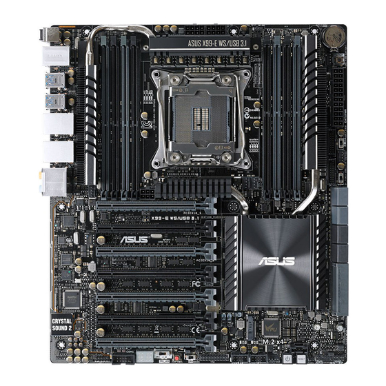
- Page 1 X99-E WS/ USB 3.1 E13611_X99-E_WS_USB31_UM_V4.indb 1 10/27/2017 16:55:58...
- Page 2 Product warranty or service will not be extended if: (1) the product is repaired, modified or altered, unless such repair, modification of alteration is authorized in writing by ASUS; or (2) the serial number of the product is defaced or missing.
-
Page 3: Table Of Contents
Contents Safety information ..................... vii About this guide ....................... viii X99-E WS/USB 3.1 specifications summary ............. x Package contents ...................... xv Installation tools and components ................. xvi Chapter 1: Product Introduction Special features..................1-1 1.1.1 Product highlights................ 1-1 1.1.2 Other special features ..............1-2 Motherboard overview ................ - Page 4 Intel(R) I210 Gigabit Network Connection - 00:1E:99:00:00:38 3-49 Monitor menu ................... 3-50 Boot menu ....................3-54 Tool menu ....................3-60 3.9.1 ASUS EZ Flash 2 Utility ............3-60 3.9.2 ASUS O.C. Profile ..............3-61 3.9.3 ASUS DRAM SPD Information ..........3-62 3.10...
- Page 5 4.4.5 USB Charger+ ................4-13 4.4.6 Push Notice ................4-14 4.4.7 System Information ..............4-17 Audio configurations ................4-18 ASUS Dr. Power Utility ................4-20 Chapter 5: RAID Support RAID configurations .................. 5-1 5.1.1 RAID definitions ................5-1 5.1.2 Installing Serial ATA hard disks ..........5-2 5.1.3...
- Page 6 Installing the device drivers ............6-10 6.2.6 Enabling the NVIDIA SLI™ technology ........6-10 ® Appendices X99-E WS/USB 3.1 block diagram (40-Lane) ............A-1 X99-E WS/USB 3.1 block diagram (28-Lane) ............A-2 Notices ........................A-3 ASUS contact information ..................A-7 E13611_X99-E_WS_USB31_UM_V4.indb 6 10/27/2017 16:55:58...
-
Page 7: Safety Information
Safety information Electrical safety • To prevent electrical shock hazard, disconnect the power cable from the electrical outlet before relocating the system. • When adding or removing devices to or from the system, ensure that the power cables for the devices are unplugged before the signal cables are connected. If possible, disconnect all power cables from the existing system before you add a device. -
Page 8: About This Guide
Refer to the following sources for additional information and for product and software updates. ASUS website The ASUS website (www.asus.com) provides updated information on ASUS hardware and software products. Optional documentation Your product package may include optional documentation, such as warranty flyers, that may have been added by your dealer. - Page 9 Conventions used in this guide To make sure that you perform certain tasks properly, take note of the following symbols used throughout this manual. DANGER/WARNING: Information to prevent injury to yourself when trying to complete a task. CAUTION: Information to prevent damage to the components when trying to complete a task.
-
Page 10: X99-E Ws/Usb 3.1 Specifications Summary
Extreme Memory Profile (XMP) ® * Hyper DIMM support is subject to the physical characteristics of individual CPUs. Refer to www.asus.com for the memory QVL (Qualified Vendors Lists). 40-LANE CPU 7 x PCI Express 3.0/2.0 x16 slots (single at x16, dual at x16/x16,... - Page 11 (MIC) - Optical S/PDIF out ports at rear I/O Intel X99 Express Chipset - supports ASUS USB 3.0 Boost ® - 4 x USB 3.0/2.0 ports at rear panel - 4 x USB 2.0/1.1 ports (4 ports at mid-board) ASMedia USB 3.1 controller - support ASUS USB 3.1 Boost...
- Page 12 X99-E WS/USB 3.1 specifications summary - EPU, EPU switch ASUS Fan Xpert3 - Featuring Fan Auto Tuning function and multiple thermistors selection for optimized system cooling control. Turbo App - Featuring automatic system performance tuning, network priority, and audio scene configuration for selected applications.
- Page 13 4-pin (PWM Mode) fan control 1 x Front panel audio connector(AAFP) 1 x S/PDIF Out header Internal I/O Connectors 1 x 5-pin Thunderbolt header for ASUS ThunderboltEX series support 1 x TPM connector 1 x 24-pin EATX Power connector 2 x 8-pin EATX 12V Power connectors...
- Page 14 System Panel (Q-Connector) 128 Mb Flash ROM, UEFI AMI BIOS, PnP, DMI 2.7, WfM 2.0, SM BIOS 2.7, ACPI 5.0, Multi-language BIOS, ASUS EZ Flash 2, CrashFree BIOS 3, F11 EZ Tuning Wizard, F6 Qfan Control, F3 My BIOS features...
-
Page 15: Package Contents
Package contents Check your motherboard package for the following items 12 x Serial ATA 6 Gb/s cables ASUS X99-E WS/USB 3.1 motherboard 1 x 3-WAY SLI bridge connector 1 x 2-in-1 ASUS Q-Connector kit 1 x ASUS Q-Shield 1 x ASUS SLI™ bridge connector... -
Page 16: Installation Tools And Components
Installation tools and components Intel LGA2011-v3 CPU ® Intel LGA2011-v3 compatible CPU Fan ® Phillips (cross) screwdriver SATA hard disk drive PC chassis DIMM 1 bag of screws Power supply unit SATA optical disc drive (optional) Graphics card The tools and components in the table above are not included in the motherboard package. E13611_X99-E_WS_USB31_UM_V4.indb 16 10/27/2017 16:56:00... -
Page 17: Chapter 1: Product Introduction
32 Gb/s. This helps enhance the performance of your SSD (Solid State Drive) that is dedicated only to the operating system. * Supports PCIe mode only. ASUS X99-E WS/USB 3.1 E13611_X99-E_WS_USB31_UM_V4.indb 1 10/27/2017 16:56:00... -
Page 18: Other Special Features
Complete USB 3.1 integration This motherboard has the latest USB 3.1 connectivity built in with dual Type-A ports for the very fastest USB data transfers — that’s up to 10 Gb/s, or twice as fast as USB 3.0. The next-generation standard is completely backward-compatible with your existing USB devices, and you’ll be all set for USB 3.1’s breakneck speeds. -
Page 19: Motherboard Overview
Before you install or remove any component, ensure that the ATX power supply is switched off or the power cord is detached from the power supply. Failure to do so may cause severe damage to the motherboard, peripherals, or components. ASUS X99-E WS/USB 3.1 E13611_X99-E_WS_USB31_UM_V4.indb 3 10/27/2017 16:56:00... -
Page 20: Motherboard Layout
1.2.2 Motherboard layout Refer to 1.2.9 Internal connectors and 2.4.1 Rear I/O connection for more information about rear panel connectors and internal connectors. Chapter 1: Product Introduction E13611_X99-E_WS_USB31_UM_V4.indb 4 10/27/2017 16:56:00... - Page 21 1-22 26. Serial port connector (10-1 pin COM1) 1-26 27. Front panel audio connector (10-1 pin AAFP) 1-28 28. Digital audio connector (4-1 pin SPDIF_OUT) 1-28 29. M.2 Socket 3 connector 1-35 ASUS X99-E WS/USB 3.1 E13611_X99-E_WS_USB31_UM_V4.indb 5 10/27/2017 16:56:00...
-
Page 22: Central Processing Unit (Cpu)
Contact your retailer immediately if the PnP cap is missing, or if you see any damage to the PnP cap/socket contacts/motherboard components. ASUS will shoulder the cost of repair only if the damage is shipment/ transit-related. -
Page 23: System Memory
Modules (DIMM) slots. A DDR4 module is notched differently from a DDR, DDR2, or DDR3 module. DO NOT install a DDR, DDR2, or DDR3 memory module to the DDR4 slot. Recommended memory configurations ASUS X99-E WS/USB 3.1 E13611_X99-E_WS_USB31_UM_V4.indb 7 10/27/2017 16:56:01... - Page 24 Hyper DIMM support is subject to the physical characteristics of individual CPUs. Load the X.M.P. or D.O.C.P. settings in the BIOS for the hyper DIMM support. • Visit the ASUS website for the latest QVL. Chapter 1: Product Introduction E13611_X99-E_WS_USB31_UM_V4.indb 8...
-
Page 25: Expansion Slots
PCIe 3.0/2.0 x16_7 slot The default setting of PCIe x16_2 slot is in Auto mode, which automatically optimizes the system bandwidth. ASUS Thunderbolt EX card is supported on PCIEX16_2 slot (Gen 2) and automatically runs at x2 mode. ASUS X99-E WS/USB 3.1 E13611_X99-E_WS_USB31_UM_V4.indb 9... - Page 26 40-LANE/28 PCI Express 3.0 operating mode LANE CPU PCIe PCIe PCIe PCIe PCIe PCIe PCIe 3.0/2.0 3.0/2.0 3.0/2.0 3.0/2.0 3.0/2.0 3.0/2.0 3.0/2.0 configuration x16_1 x16_2 x16_3 x16_4 x16_5 x16_6 x16_7 Single VGA/ (single VGA PCIe card recommended) Dual VGA/PCIe cards Triple VGA/ PCIe cards Quad VGA/...
- Page 27 EHCI 2 – – shared – – – – – ® HD Audio – – – – – – shared – ASMedia Controller – – shared – – – – – (1142) ASUS X99-E WS/USB 3.1 1-11 E13611_X99-E_WS_USB31_UM_V4.indb 11 10/27/2017 16:56:01...
-
Page 28: Onboard Buttons And Switches
1.2.6 Onboard buttons and switches Onboard buttons and switches allow you to fine-tune performance when working on a bare or open-case system. This is ideal for overclockers and gamers who continually change settings to enhance system performance. Power-on button The motherboard comes with a power-on button that allows you to power up or wake up the system. - Page 29 BIOS default settings. A message will appear during POST reminding you that the BIOS has been restored to its default settings. • We recommend that you download and update to the latest BIOS version from www.asus.com after using the MemOK! function. ASUS X99-E WS/USB 3.1 1-13 E13611_X99-E_WS_USB31_UM_V4.indb 13...
- Page 30 TPU switch With its two-level adjustment functions, the TPU allows you to automatically adjusts the CPU ratio and clock speed for an optimal system performance. • Enable this switch when the system is powered off. • When the TPU switch is set to Enabled (TPU_I: CPU Ratio Boost), the system automatically adjusts the CPU ratio for an enhanced performance.
- Page 31 You may change the EPU settings in the software application or BIOS setup program and enable the EPU function at the same time. However, the system will use the last setting you have made. ASUS X99-E WS/USB 3.1 1-15 E13611_X99-E_WS_USB31_UM_V4.indb 15...
- Page 32 Dr. Power switch (DR_POWER) This switch allows you to enable or disable the ASUS Dr. Power feature. Install the bundled ASUS Dr. Power Utility then enable this switch to allow the system to display notification messages in your Windows screen if a problem is detected with your Power Supply Unit (PSU).
- Page 33 DIMM’s speed and performance. The EZ XMP LED (XLED1) lights up when you enable the EZ XMP switch. the location of the EZ XMP LED, refer to section 1.2.8 Onboard LEDs. ASUS X99-E WS/USB 3.1 1-17 E13611_X99-E_WS_USB31_UM_V4.indb 17 10/27/2017 16:56:03...
-
Page 34: Jumpers
1.2.7 Jumpers CPU Over Voltage jumper (3-pin CPU_OV) The CPU Over Voltage jumper allows you to set a higher CPU voltage for a flexible overclocking system, depending on the type of the installed CPU. To gain more CPU voltage setting, insert the jumper to pins 2-3. To go back to its default CPU voltage setting, insert the jumper to pins 1-2. -
Page 35: Onboard Leds
On-Self Test): CPU, memory modules, VGA card, and hard disk drives. If an error is found, the critical component’s LED stays lit up until the problem is solved. TPU LED (TPU_LED) The TPU LED lights up when the TPU switch is enabled. ASUS X99-E WS/USB 3.1 1-19 E13611_X99-E_WS_USB31_UM_V4.indb 19 10/27/2017 16:56:03... - Page 36 EPU LED (O2LED3) The EPU LED lights up when the EPU switch is enabled. EZ XMP LED (XLED1) This LED lights up when you enable the EZ XMP switch. Chapter 1: Product Introduction 1-20 E13611_X99-E_WS_USB31_UM_V4.indb 20 10/27/2017 16:56:03...
- Page 37 This LED near the Dr. Power switch lights up when the Dr. Power switch is enabled. PWR_SUPPLY LED The ASUS Dr. Power LED near the EATX PWR connector lights up when the ASUS Dr. Power switch setting is on and the power supply unit has failed.
- Page 38 Power LED (+12V_PWR LED) The Power LED near the EATX12V1 connector lights up when you enable the ASUS Dr. Power switch and if there is no power detected on the 8-pin EATX12V connector. Q-Code LEDs The Q-Code LED design provides you with a 2-digit error code that displays the system status.
- Page 39 Recovery firmware image is found Recovery firmware image is loaded Reserved for future AMI progress codes F5 – F7 Recovery PPI is not available Recovery capsule is not found (continued on the next page) ASUS X99-E WS/USB 3.1 1-23 E13611_X99-E_WS_USB31_UM_V4.indb 23 10/27/2017 16:56:04...
- Page 40 Code Description Invalid recovery capsule Reserved for future AMI error codes FB – FF DXE Core is started NVRAM initialization Installation of the PCH Runtime Services CPU DXE initialization is started 63 – 67 PCI host bridge initialization System Agent DXE initialization is started System Agent DXE SMM initialization is started System Agent DXE initialization (System Agent module specific) 6B –...
- Page 41 System is waking up from the S4 sleep state System has transitioned into ACPI mode. Interrupt controller is in PIC mode. System has transitioned into ACPI mode. Interrupt controller is in APIC mode. ASUS X99-E WS/USB 3.1 1-25 E13611_X99-E_WS_USB31_UM_V4.indb 25...
-
Page 42: Internal Connectors
1.2.9 Internal connectors ASMedia ® Serial ATA 6 Gb/s connectors (7-pin SATA6G_E12/SATAEXPRESS_E1) These connectors connect to Serial ATA 6 Gb/s hard disk drives via Serial ATA 6 Gb/s signal cables. • ASMedia storage controller can only support AHCI mode. • These SATA ports are for data drives only. - Page 43 The SATAEXPRESS_1 connector can support one SATA Express device or two SATA devices. • Due to chipset behavior, the SATA6G_78 and SATA6G_910 ports (black) do not support Intel Rapid Storage Technology and RAID configuration. ® ASUS X99-E WS/USB 3.1 1-27 E13611_X99-E_WS_USB31_UM_V4.indb 27 10/27/2017 16:56:05...
- Page 44 Digital audio connector (4-1 pin SPDIF_OUT) This connector is for an additional Sony/Philips Digital Interface (S/PDIF) port. Connect the S/PDIF Out module cable to this connector, then install the module to a slot opening at the back of the system chassis. The S/PDIF module is purchased separately.
- Page 45 The plugged USB 3.0 device may run on xHCI or EHCI mode depending on the operating system’s setting. • These USB 3.0 ports support native UASP transfer standard in Windows ® Windows 8.1 and Turbo Mode when using USB 3.0 Boost feature. ® ASUS X99-E WS/USB 3.1 1-29 E13611_X99-E_WS_USB31_UM_V4.indb 29 10/27/2017 16:56:05...
- Page 46 DO NOT connect a 1394 cable to the USB connectors. Doing so will damage the motherboard! You can connect the front panel USB cable to the ASUS Q-Connector (USB) first, and then install the Q-Connector (USB) to the USB connector onboard if your chassis supports front panel USB ports.
- Page 47 • The CPU_FAN connector supports the CPU fan of maximum 1A (12 W) fan power. • The CPU_FAN and CHA_FAN connectors support the ASUS FAN Xpert 3 feature on X99 platform. • The CPU fan connector detects the type of CPU fan installed and automatically switches the control modes.
- Page 48 ATX power connectors (24-pin EATXPWR; 8-pin EATX12V; 8-pin EATX12V1; 6-pin EATX12V_1) These connectors are for ATX power supply plugs. The power supply plugs are designed to fit these connectors in only one orientation. Find the proper orientation and push down firmly until the connectors completely fit. •...
- Page 49 Pressing the power switch for more than four seconds while the system is ON turns the system OFF. • Reset button (2-pin RESET) This 2-pin connector is for the chassis-mounted reset button for system reboot without turning off the system power. ASUS X99-E WS/USB 3.1 1-33 E13611_X99-E_WS_USB31_UM_V4.indb 33 10/27/2017 16:56:06...
- Page 50 TPM connector (20-1 pin TPM) This connector supports a Trusted Platform Module (TPM) system, which securely store keys, digital certificates, passwords and data. A TPM system also helps enhance network security, protect digital identities, and ensures platform integrity. The TPM module is purchased separately. DirectKey connector (2-pin DRCT) This connector is for the chassis-mounted button that supports the DirectKey function.
- Page 51 M.2 socket 3 This socket allows you to install an M.2 (NGFF) SSD module. • This socket supports M Key and type 2260/2280 storage devices. • This socket supports PCIe mode only. ASUS X99-E WS/USB 3.1 1-35 E13611_X99-E_WS_USB31_UM_V4.indb 35 10/27/2017 16:56:06...
- Page 52 Chassis intrusion connector (4-1 pin CHASSIS) This connector is for a chassis-mounted intrusion detection sensor or switch. Connect one end of the chassis intrusion sensor or switch cable to this connector. The chassis intrusion sensor or switch sends a high-level signal to this connector when a chassis component is removed or replaced.
- Page 53 T_Sensor connector (2-pin T_SENSOR1) This connector is for the thermistor cable that allows you to monitor the temperature of your motherboard’s critical components and connected devices. The thermistor cable is purchased separately. ASUS X99-E WS/USB 3.1 1-37 E13611_X99-E_WS_USB31_UM_V4.indb 37 10/27/2017 16:56:07...
- Page 54 Chapter 1: Product Introduction 1-38 E13611_X99-E_WS_USB31_UM_V4.indb 38 10/27/2017 16:56:07...
-
Page 55: Chapter 2: Basic Installation
2.1.1 Motherboard installation Install the ASUS Q-Shield to the chassis rear I/O panel. Place the motherboard into the chassis, ensuring that its rear I/O ports are aligned to the chassis’ rear I/O panel. - Page 56 Place nine screws into the holes indicated by circles to secure the motherboard to the chassis. DO NOT overtighten the screws! Doing so can damage the motherboard. Chapter 2: Basic Installation E13611_X99-E_WS_USB31_UM_V4.indb 2 10/27/2017 16:56:07...
-
Page 57: Cpu Installation
The plastic cap will pop up automatically once the CPU is in place and the hatch properly sealed down. ASUS X99-E WS/USB 3.1 E13611_X99-E_WS_USB31_UM_V4.indb 3 10/27/2017 16:56:08... - Page 58 Triangle mark Triangle mark Chapter 2: Basic Installation E13611_X99-E_WS_USB31_UM_V4.indb 4 10/27/2017 16:56:09...
-
Page 59: Cpu Heatsink And Fan Assembly Installation
CPU heatsink and fan assembly installation Apply the Thermal Interface Material to the CPU heatsink and CPU before you install the heatsink and fan, if necessary. To install the CPU heatsink and fan assembly ASUS X99-E WS/USB 3.1 E13611_X99-E_WS_USB31_UM_V4.indb 5 10/27/2017 16:56:09... -
Page 60: Dimm Installation
2.1.4 DIMM installation To remove a DIMM Chapter 2: Basic Installation E13611_X99-E_WS_USB31_UM_V4.indb 6 10/27/2017 16:56:09... -
Page 61: Atx Power Connection
2.1.5 ATX Power connection ASUS X99-E WS/USB 3.1 E13611_X99-E_WS_USB31_UM_V4.indb 7 10/27/2017 16:56:09... -
Page 62: Sata Device Connection
2.1.6 SATA device connection Chapter 2: Basic Installation E13611_X99-E_WS_USB31_UM_V4.indb 8 10/27/2017 16:56:10... -
Page 63: Front I/O Connector
2.1.7 Front I/O Connector To install ASUS Q-Connector To install USB 2.0 connector To install front panel audio connector AAFP USB 2.0 To install USB 3.0 connector USB 3.0 ASUS X99-E WS/USB 3.1 E13611_X99-E_WS_USB31_UM_V4.indb 9 10/27/2017 16:56:10... -
Page 64: Expansion Card Installation
2.1.8 Expansion Card installation To install PCIe x16 cards Chapter 2: Basic Installation 2-10 E13611_X99-E_WS_USB31_UM_V4.indb 10 10/27/2017 16:56:10... -
Page 65: Bios Update Utility
BIOS Flashback is not operating properly. This may be caused by improper installation of the USB storage device and filename/file format error. If this scenario happens, please restart the system to turn off the light. • Updating BIOS may have risks. If the BIOS program is damaged during the process and results to the system’s failure to boot up, please contact your local ASUS Service Center. ASUS X99-E WS/USB 3.1 2-11 E13611_X99-E_WS_USB31_UM_V4.indb 11... -
Page 66: Q-Code Logger Utility
Q-Code Logger utility 2.3.1 Using the Q-Code Logger Q-Code Logger allows you to easily check Q-Code event logs without opening the system’s case. To use the Q-Code Logger: Insert the USB storage device to the dedicated Q-Code Logger USB port. Press the Q-Code Logger button for three seconds until the Q-Code Logger LED blinks three times, indicating that the Q-Code Logger function is enabled. -
Page 67: Motherboard Rear And Audio Connections
USB BIOS Flashback Optical S/PDIF Out port eSATA ports 12 Audio I/O ports*** * and **: Refer to the tables on the next page for the LAN port LEDs and audio port definitions. ASUS X99-E WS/USB 3.1 2-13 E13611_X99-E_WS_USB31_UM_V4.indb 13 10/27/2017 16:56:11... - Page 68 • The plugged USB 3.0 device may run on xHCI mode or EHCI mode, depending on the operating system’s setting. • USB 3.0 devices can only be used as data storage only. • We strongly recommend that you connect USB 3.0 devices to USB 3.0 ports for faster and better performance for your USB 3.0 devices. • Due to the design of the Intel X99 series chipset, all USB devices connected to the ® USB 2.0 and USB 3.0 ports are controlled by the xHCI controller. Some legacy USB devices must update their firmware for better compatibility. * LAN ports LED indications Activity Link LED Speed LED Status Description Status Description...
-
Page 69: Audio I/O Connections
2.4.2 Audio I/O connections Audio I/O ports Connect to Headphone and Mic Connect to Stereo Speakers ASUS X99-E WS/USB 3.1 2-15 E13611_X99-E_WS_USB31_UM_V4.indb 15 10/27/2017 16:56:11... - Page 70 Connect to 2.1 channel Speakers Connect to 4.1 channel Speakers Connect to 5.1 channel Speakers Chapter 2: Basic Installation 2-16 E13611_X99-E_WS_USB31_UM_V4.indb 16 10/27/2017 16:56:11...
-
Page 71: Starting Up For The First Time
If you do not see anything within 30 seconds from the time you turned on the power, the system may have failed a power-on test. Check the jumper settings and connections or call your retailer for assistance. ASUS X99-E WS/USB 3.1 2-17 E13611_X99-E_WS_USB31_UM_V4.indb 17... -
Page 72: Turning Off The Computer
BIOS Beep Description One short beep VGA detected Quick boot set to disabled No keyboard detected One continuous beep followed by two No memory detected short beeps then a pause (repeated) One continuous beep followed by three No VGA detected short beeps One continuous beep followed by four Hardware component failure... -
Page 73: Chapter 3: Bios Setup
BIOS Setup Knowing BIOS The new ASUS UEFI BIOS is a Unified Extensible Interface that complies with UEFI architecture, offering a user-friendly interface that goes beyond the traditional keyboard- only BIOS controls to enable a more flexible and convenient mouse input. You can easily navigate the new UEFI BIOS with the same smoothness as your operating system. -
Page 74: Bios Setup Program
BIOS setup program Use the BIOS Setup to update the BIOS or configure its parameters. The BIOS screen include navigation keys and brief onscreen help to guide you in using the BIOS Setup program. Entering BIOS at startup To enter BIOS Setup at startup, press <Delete> during the Power-On Self Test (POST). If you do not press <Delete>, POST continues with its routines. -
Page 75: Ez Mode
Saves the changes and resets the system The boot device options vary depending on the devices you installed to the system. ASUS X99-E WS/USB 3.1 E13611_X99-E_WS_USB31_UM_V4.indb 3 10/27/2017 16:56:12... -
Page 76: Advanced Mode
3.2.2 Advanced Mode The Advanced Mode provides advanced options for experienced end-users to configure the BIOS settings. The figure below shows an example of the Advanced Mode. Refer to the following sections for the detailed configurations. To switch from EZ Mode to Advanced Mode, click Advanced Mode or press F7 hotkey. Q-Fan control EZ Tuning Wizard MyFavorite... - Page 77 This button above the menu bar allows you to view and tweak the overclocking settings of your system. It also allows you to change the motherboard’s SATA mode from AHCI to RAID mode. Refer to section 3.2.4 EZ Tuning Wizard for more information. ASUS X99-E WS/USB 3.1 E13611_X99-E_WS_USB31_UM_V4.indb 5 10/27/2017 16:56:12...
- Page 78 Quick Note (F9) This button above the menu bar allows you to key in notes of the activities that you have done in BIOS. • The Quick Note function does not support the following keyboard functions: delete, cut, copy and paste. •...
-
Page 79: Qfan Control
Select a profile to apply to Click to apply the fan setting your fans Click to undo the Click to go back to main menu changes Select to manually configure your fans ASUS X99-E WS/USB 3.1 E13611_X99-E_WS_USB31_UM_V4.indb 7 10/27/2017 16:56:13... - Page 80 Configuring fans manually Select Manual from the list of profiles to manually configure your fans’ operating speed. Speed points Click or tap to manually configure your fans To configure your fans: Select the fan that you want to configure and to view its current status. Click and drag the speed points to adjust the fans’...
-
Page 81: Ez Tuning Wizard
Next. If you are not sure of the CPU fan type, click I’m not sure. The system automatically detects the CPU fan type. Click Next then click Yes to confirm auto-tuning. ASUS X99-E WS/USB 3.1 E13611_X99-E_WS_USB31_UM_V4.indb 9 10/27/2017 16:56:13... - Page 82 Creating RAID To create RAID: Press <F11> on your keyboard or click from the BIOS screen to open EZ Tuning Wizard screen. Click RAID then click Next. • Ensure that your HDDs have no existing RAID volumes. • Ensure to connect your HDDs to Intel SATA connectors.
-
Page 83: My Favorites
My Favorites MyFavorites is your personal space where you can easily save and access your favorite BIOS items. ASUS X99-E WS/USB 3.1 3-11 E13611_X99-E_WS_USB31_UM_V4.indb 11 10/27/2017 16:56:14... - Page 84 Adding items to My Favorites To add BIOS items: Press <F3> on your keyboard or click from the BIOS screen to open Setup Tree Map screen. On the Setup Tree Map screen, select the BIOS items that you want to save in MyFavorites screen.
-
Page 85: Main Menu
RTC RAM via the Clear CMOS button. • The Administrator or User Password items on top of the screen show the default [Not Installed]. After you set a password, these items show [Installed]. ASUS X99-E WS/USB 3.1 3-13 E13611_X99-E_WS_USB31_UM_V4.indb 13 10/27/2017 16:56:14... - Page 86 Administrator Password If you have set an administrator password, we recommend that you enter the administrator password for accessing the system. Otherwise, you might be able to see or change only selected fields in the BIOS setup program. To set an administrator password: Select the Administrator Password item and press <Enter>.
-
Page 87: Ai Tweaker Menu
This item allows you to select a strap close to your target BCLK (base clock) for an extreme overclocking, or leave it at [Auto] for the BIOS to upgrade. Configuration options: [Auto] [100MHz] [125MHz] [166MHz] [250MHz] ASUS X99-E WS/USB 3.1 3-15 E13611_X99-E_WS_USB31_UM_V4.indb 15... - Page 88 The value ranges depend on the value you set on BCLK Frequency. ASUS MultiCore Enhancement [Auto] [Auto] This item allows you to maximize the oveclocking performance optimized by ASUS core ratio settings. [Disabled] This item allows you to set to default core ratio settings. CPU Core Ratio [Per Core] This item allows you to set the CPU core ratio limit per core or synchronize automatically to all cores.
- Page 89 This item allows you to set the maximum possible ratio on the Uncore part of the processor. Use the <+> or <-> keys to adjust the value. The values depend on the CPU installed. ASUS X99-E WS/USB 3.1 3-17 E13611_X99-E_WS_USB31_UM_V4.indb 17...
- Page 90 [Keep Current Settings]. EPU Power Saving Mode [Disabled] The ASUS EPU (Energy Processing Unit) sets the CPU in its minimum power consumption settings. Enable this item to set lower CPU VCCIN and Vcore voltages and achieve the best energy saving condition.
- Page 91 DRAM WRITE to READ Delay(tWTR_L) [Auto] Configuration options: [Auto] [1] – [15] DRAM CKE Minimum Pulse Width [Auto] Configuration options: [Auto] [4] – [8] DRAM Write Latency [Auto] Configuration options: [Auto] [1] – [31] ASUS X99-E WS/USB 3.1 3-19 E13611_X99-E_WS_USB31_UM_V4.indb 19 10/27/2017 16:56:15...
- Page 92 Third Timings tRRDR [Auto] Configuration options: [Auto] [1] - [7] tRRDD [Auto] Configuration options: [Auto] [1] - [7] tWWDR [Auto] Configuration options: [Auto] [1] - [7] tWWDD [Auto] Configuration options: [Auto] [1] - [7] tRWDR [Auto] Configuration options: [Auto] [1] - [7] tWRDR [Auto] Configuration options: [Auto] [1] - [7] tWRDD [Auto]...
- Page 93 DRAM IO-L (CHB D0 R0) [Auto] Configuration options: [Auto] [1] - [255] DRAM IO-L (CHB D0 R1) [Auto] Configuration options: [Auto] [1] - [255] DRAM IO-L (CHB D1 R0) [Auto] Configuration options: [Auto] [1] - [255] ASUS X99-E WS/USB 3.1 3-21 E13611_X99-E_WS_USB31_UM_V4.indb 21 10/27/2017 16:56:15...
- Page 94 DRAM IO-L (CHB D1 R1) [Auto] Configuration options: [Auto] [1] - [255] DRAM IO-L (CHC D0 R0) [Auto] Configuration options: [Auto] [1] - [255] DRAM IO-L (CHC D0 R1) [Auto] Configuration options: [Auto] [1] - [255] DRAM IO-L (CHC D1 R0) [Auto] Configuration options: [Auto] [1] - [255] DRAM IO-L (CHC D1 R1) [Auto] Configuration options: [Auto] [1] - [255]...
- Page 95 Configuration options: [Auto] [1.00] - [1.60] Receiver ODT Pre-emphasis [Auto] Configuration options: [Auto] [1.00] - [1.60] Transmitter ODT Pre-emphasis [Auto] Configuration options: [Auto] [1.00] - [1.60] Transmitter ODT De-emphasis [Auto] Configuration options: [Auto] [1.00] - [1.60] ASUS X99-E WS/USB 3.1 3-23 E13611_X99-E_WS_USB31_UM_V4.indb 23 10/27/2017 16:56:15...
- Page 96 MISC DRAM Eventual Voltage (CHA/CHB/CHC/CHD) [Auto] Use <+> or <-> to adjust the eventual voltages of the DIMM slots. The values range from 0.8 V to 1.9 V with a 0.10 V increment. DRAM CLK Period [Auto] This item allows you to set a DRAM clock period. Configuration options: [Auto] [1] –...
- Page 97 [T. Probe] Select to maintain the VRM thermal balance. [Extreme] Select to maintain the current VRM balance. DO NOT remove the thermal module. The thermal conditions should be monitored. ASUS X99-E WS/USB 3.1 3-25 E13611_X99-E_WS_USB31_UM_V4.indb 25 10/27/2017 16:56:15...
- Page 98 CPU Current Capability [Auto] This item provides a total power range for CPU overclocking. A higher value setting provides higher power consumption delivery and extends the overclocking frequency range simultaneously. Configuration options: [Auto] [100%] [110%] [120%] [130%] [140%] CPU Power Thermal Control [120] A higher temperature brings a wider CPU power thermal range and extends the overclocking tolerance to enlarge the overclocking potential.
- Page 99 The following item appeara only when you set Max. Vcore item to [Enabled]. Max Cache Voltage [Disabled] This item allows the CPU Core Voltage as close to CPU Input Voltage as possible. ASUS X99-E WS/USB 3.1 3-27 E13611_X99-E_WS_USB31_UM_V4.indb 27 10/27/2017 16:56:15...
- Page 100 CPU Core Voltage [Auto] This item allows you to configure the amount of Voltage fed to the CPU cores. Increase the voltage when configuring a high CPU core frequency. Configuration options: [Auto] [Manual Mode] [Offset Mode] [Adaptive Mode] The following item appears only when you set the CPU Core Voltage to [Manual Mode]. CPU Core Voltage Override [Auto] This item allows you to configure the CPU core voltage.
- Page 101 This item allows you to set a VCCIN for the CPU before OS loading. Use the <+> or <-> key to adjust the value. The values range from 0.001 V to 2.440 V at 0.001 V increment. ASUS X99-E WS/USB 3.1 3-29 E13611_X99-E_WS_USB31_UM_V4.indb 29...
- Page 102 CPU Input Voltage [Auto] This item allows you to configure the input voltage for the CPU by the external voltage regulator. Use the <+> or <-> key to adjust the value. The values range from 0.80 V to 2.70 V at 0.010 V increment.
- Page 103 This item allows you to enhance the BCLK overclocking capability or reduce the EMI (electromagnetic disturbance) generated by the BCLK. Set this item to [Enabled] for EMI reduction, or set this item to [Disabled] to enhance BCLK overclocking. Configuration options: [Auto] [Disabled] [Enabled] ASUS X99-E WS/USB 3.1 3-31 E13611_X99-E_WS_USB31_UM_V4.indb 31 10/27/2017 16:56:15...
-
Page 104: Advanced Menu
Advanced menu The Advanced menu items allow you to change the settings for the CPU and other system devices. Be cautious when changing the settings of the Advanced menu items. Incorrect field values can cause the system to malfunction. Chapter 3: BIOS Setup 3-32 E13611_X99-E_WS_USB31_UM_V4.indb 32 10/27/2017 16:56:16... -
Page 105: Cpu Configuration
Execute Disable Bit [Enabled] Execute Disable prevents certain classes of malicious buffer overflow attacks when combined with a supporting OS (SuSE Linux 9.2, RedHat Enterprise 3 Update 3). Configuration options: [Disabled] [Enabled] ASUS X99-E WS/USB 3.1 3-33 E13611_X99-E_WS_USB31_UM_V4.indb 33 10/27/2017 16:56:16... - Page 106 Intel Virtualization Technology [Disabled] When set to [Enabled], a VMM can utilize the additional hardware capabilities provided by Vanderpool Technology. Configuration options: [Disabled] [Enabled] Hardware Prefetcher [Enabled] This item allows the CPU to prefetch commands and data in the L2 cache, reduces the DRAM loading time and improves the system performance.
-
Page 107: Pch Configuration
This item allows your system to automatically select the PCI Express port speed. When set to [Gen1], the PCI-E port runs at PCI-E 1.0 speed. When set to [Gen2], the PCI-E port runs at PCI-E 2.0 speed. Configuration options: [Auto] [Gen1] [Gen2] ASUS X99-E WS/USB 3.1 3-35 E13611_X99-E_WS_USB31_UM_V4.indb 35 10/27/2017 16:56:16... -
Page 108: Pch Storage Configuration
When set to [Auto], this item allows the system to automatically adjust the SRIS (Separate Reference Clock Independent Spread Spectrum Clocking Architecture) support for connected SATA Express devices. Set this item to [Disabled] to activate ASUS RUNWAY SATA Express bridge card Configuration options: [Auto] [Disabled] S.M.A.R.T. - Page 109 When disabled, the hot plug function of SATA ports are disabled. Configuration options: [Disabled] [Enabled] Hot Plug [Disabled] (SATA6G_1-6 (Gray) / SATA6G_7-10 (Black)) These items allow you to enable/disable SATA Hot Plug Support. Configuration options: [Disabled] [Enabled] ASUS X99-E WS/USB 3.1 3-37 E13611_X99-E_WS_USB31_UM_V4.indb 37 10/27/2017 16:56:16...
-
Page 110: System Agent Configuration
3.6.4 System Agent Configuration NB PCI-E Configuration The items in this menu allow you to select the operating speeds of the PCIe slots. PCIEX16_1 Link Speed [Auto] This item allows you to select the operating speed of the PCIEX16_1 slot. Configuration options: [Auto] [Gen1] [Gen2] [Gen3] PCIEX16_2 Link Speed [Auto] This item allows you to select the operating speed of the PCIEX16_2 slot. - Page 111 This item allows you to enable/disable the Non-Isoch VT_D Engine Coherency Support. Configuration options: [Enabled] [Disabled] Coherency Support (Isoch) [Enabled] This item allows you to enable/disable the Isoch VT_D Engine Coherency Support. Configuration options: [Enabled] [Disabled] ASUS X99-E WS/USB 3.1 3-39 E13611_X99-E_WS_USB31_UM_V4.indb 39 10/27/2017 16:56:16...
-
Page 112: Usb Configuration
3.6.5 USB Configuration The items in this menu allow you to change the USB-related features. The Mass Storage Devices item shows the auto-detected values. If no USB device is detected, the item shows None. Intel xHCI Mode [Smart Auto] [Auto] The xHCI is automatically enabled and runs at USB 3.0 mode when the xHCI driver is installed in the operating system. - Page 113 Disables the EHCI Hand-off support. USB Single Port Control This item allows you to enable or disable the individual USB ports. Refer to section 1.2.2 Motherboard layout for the location of the USB ports. ASUS X99-E WS/USB 3.1 3-41 E13611_X99-E_WS_USB31_UM_V4.indb 41 10/27/2017 16:56:17...
-
Page 114: Platform Misc Configuration
3.6.6 Platform Misc Configuration The items in this menu allow you to configure the platform-related features. SA - PCI Express SA SMI ASPM [Disabled] This item allows you to enable/disable the ASPM (L1) support for the downstream devices. Configuration options: [Auto] [Disabled] [L1 only] PEG ASPM Support [Disabled] This item allows you to enable/disable the ASPM support for the downstream devices. -
Page 115: Onboard Devices Configuration
[AC97] Sets the front panel audio connector (AAFP) mode to legacy AC’97. SPDIF Out Type [SPDIF] [SPDIF] Sets to an SPDIF audio output. [HDMI] Sets to an HDMI audio output. ASUS X99-E WS/USB 3.1 3-43 E13611_X99-E_WS_USB31_UM_V4.indb 43 10/27/2017 16:56:17... - Page 116 PCI-EX16_2 Slot (Black) Bandwidth [Audio] [Auto] Runs at x8 mode when the installed PCIe device is higher than x4 interface for high system performance. [X2 Mode] Runs at x2 mode with USB3.1_E12 enabled. The SATAEXPRESS_E1 is disabled. [X4 Mode] Runs at x4 mode for a high performance support with USB3.1_E12 and the SATAEXPRESS_E1 is disabled.
- Page 117 Independent Spectrum Clocking Architecture) support for connected SATA Express devices. [Disabled] Select for ASUS RUNWAY SATA Express bridge card. Intel LAN Controller (LAN1-LAN2) [Enabled] This item allows you to enable or disable the Intel LAN1/2 controllers. Configuration options: [Disabled] [Enabled] The following item appears only when you set the Intel LAN Controller to [Enabled].
-
Page 118: Apm Configuration
3.6.8 APM Configuration ErP Ready [Disabled] This item allows you to switch off some power at S4+S5 or S5 to get the system ready for ErP requirement. When set to [Enabled], all other PME options are switched off. Configuration options: [Disabled] [Enabled (S4+S5] [Enabled (S5)] Restore AC Power Loss [Power Off] This item allows your system to go to ON state, OFF state, or both states after an AC power loss. -
Page 119: Network Stack Configuration
This item allows you to set a wait time to press ESC key to abort the PXE boot. You can use the <+> or <-> keys to adjust the value. The values range from 0 to 5 seconds. ASUS X99-E WS/USB 3.1 3-47 E13611_X99-E_WS_USB31_UM_V4.indb 47... -
Page 120: Intel(R) Ethernet Connection (2) I218-Lm 00:1E:99:00:00:37
3.6.10 Intel(R) Ethernet Connection (2) I218-LM 00:1E:99:00:00:37 NIC Configuration The items in this menu allow you to configure the boot protocol, Wake-on LAN, link speed, and virtual LAN. Link Speed [Auto Negotiated] This item allows you to specify the port speed used for the selected boot protocol. Configuration options: [Auto Negotiated] [10 Mbps Half] [10 Mbps Full] [100 Mbps Half] [100 Mbps Full] Wake On LAN [Enabled]... -
Page 121: Intel(R) I210 Gigabit Network Connection - 00:1E:99:00:00:38
Blink LEDs [0] This item allows you to identify the physical network port with the blinking associated LEDs. Use the number keys to key in the number. The values range from 0 to 15. ASUS X99-E WS/USB 3.1 3-49 E13611_X99-E_WS_USB31_UM_V4.indb 49... -
Page 122: Monitor Menu
Monitor menu The Monitor menu displays the system temperature/power status, and allows you to change the fan settings. Scroll down to display the other BIOS items. CPU Temperature / MB Temperature / VRM Temperature / PCH Core Temperature / T-SENSOR1 Temperature [xxx°C/xxx°F] The onboard hardware monitor automatically detects and displays the CPU, motherboard, VRM, PCH Core, and T-SENSOR1 temperatures. - Page 123 20% to 75%. CPU Fan Min. Duty Cycle(%) [20] Use the <+> or <-> keys to adjust the minimum CPU fan duty cycle. The values may differ via Qfan tuning. ASUS X99-E WS/USB 3.1 3-51 E13611_X99-E_WS_USB31_UM_V4.indb 51 10/27/2017 16:56:18...
- Page 124 Chassis Fan 1/4 Q-Fan Control [DC Mode] These items allow you to set the chassis fans’ Q-Fan control feature into DC Mode, PWM Mode, or disable these Q-Fan controls from your motherboard. Configuration options: [Disabled] [DC Mode] [PWM Mode] The following items appear only when you set the Chassis Fan 1/4 Q-Fan Control to [Disabled].
- Page 125 Configuration options: [ON] [OFF] Chassis Intrude Detect Support [ON] This item allows you to on/off the chassis intrude detect feature. Configuration options: [ON] [OFF] ASUS X99-E WS/USB 3.1 3-53 E13611_X99-E_WS_USB31_UM_V4.indb 53 10/27/2017 16:56:18...
-
Page 126: Boot Menu
Boot menu The Boot menu items allow you to change the system boot options. Boot Configuration Fast Boot [Enabled] [Disabled] This item allows your system to go back to its normal boot speed. [Enabled] This item allows your system to accelerate the boot speed. The following items appear only when you set the Fast Boot to [Enabled]. - Page 127 Configuration options: [On] [Off] Wait For ‘F1’ If Error [Enabled] This item allows your system to wait for the <F1> key to be pressed when error occurs. Configuration options: [Disabled] [Enabled] ASUS X99-E WS/USB 3.1 3-55 E13611_X99-E_WS_USB31_UM_V4.indb 55 10/27/2017 16:56:19...
- Page 128 Option ROM Messages [Force BIOS] This item allows you to set the display mode for Option ROM. Configuration options: [Force BIOS] [Keep Current] INT19 Trap Response [Immediate] [Immediate] Executes the trap for INT19 immediately. [Postponed] Executes the trap during legacy boot. Above 4G Decoding [Disabled] This item allows you to decode the 64-bit capable devices above 4G address space.
- Page 129 Load PK from File This item allows you to load the downloaded PK from a USB storage device. The PK file must be formatted as a UEFI variable structure with time-based authenticated variable. ASUS X99-E WS/USB 3.1 3-57 E13611_X99-E_WS_USB31_UM_V4.indb 57 10/27/2017 16:56:19...
- Page 130 KEK Management The KEK (Key-exchange Key or Key Enrollment Key) manages the Signature database (db) and Revoked Signature database (dbx). Key-exchange Key (KEK) refers to Microsoft Secure Boot Key-Enrollment Key (KEK). ® Delete the KEK This item allows you to delete the KEK from your system. Configuration options: [Yes] [No] Load KEK from File This item allows you to load the downloaded KEK from a USB storage...
- Page 131 ® ® supported). • To select the boot device during system startup, press <F8> when ASUS Logo appears. Boot Override These item displays the available devices. The number of device items that appear on the screen depends on the number of devices installed in the system. Click an item to start booting from the selected device.
-
Page 132: Tool Menu
3.9.1 ASUS EZ Flash 2 Utility This item allows you to run ASUS EZ Flash 2. When you press <Enter>, a confirmation message appears. Use the left/right arrow key to select between [Yes] or [No], then press <Enter> to confirm your choice. -
Page 133: Asus O.c. Profile
Key in a profile number from one to eight, press <Enter>, and then select Yes. Load/Save Profile from/to USB Drive This item allows you to load or save profile from your USB drive, load and save profile to your USB drive. ASUS X99-E WS/USB 3.1 3-61 E13611_X99-E_WS_USB31_UM_V4.indb 61 10/27/2017 16:56:19... -
Page 134: Asus Dram Spd Information
3.9.3 ASUS DRAM SPD Information This item allows you to view the DRAM SPD information. Chapter 3: BIOS Setup 3-62 E13611_X99-E_WS_USB31_UM_V4.indb 62 10/27/2017 16:56:20... -
Page 135: Exit Menu
<Esc>, a confirmation window appears. Select Yes to discard changes and exit. Launch EFI Shell from USB drives This option allows you to attempt to launch the EFI Shell application (shellx64.efi) from one of the available filesystem devices. ASUS X99-E WS/USB 3.1 3-63 E13611_X99-E_WS_USB31_UM_V4.indb 63 10/27/2017 16:56:20... -
Page 136: Updating Bios
3.11.2 ASUS EZ Flash 2 ASUS EZ Flash 2 allows you to update the BIOS without having to use a bootable floppy disk or an OS-based utility. Before you start using this utility, download the latest BIOS from the ASUS website at www.asus.com. - Page 137 Ensure to load the BIOS default settings to ensure system compatibility and stability. Select the Load Optimized Defaults item under the Exit menu. See section 3.10 Exit Menu for details. ASUS X99-E WS/USB 3.1 3-65 E13611_X99-E_WS_USB31_UM_V4.indb 65 10/27/2017 16:56:20...
-
Page 138: Asus Crashfree Bios 3
The BIOS file in the motherboard support DVD may be older than the BIOS file published on the ASUS official website. If you want to use the newer BIOS file, download the file at https://www.asus.com/support/ and save it to a USB flash drive. - Page 139 Welcome to FreeDOS (http://www.freedos.org)! C:/> d: D:/> Updating the BIOS file To update the BIOS file: On the FreeDOS prompt, type bupdater /pc /g and press <Enter>. D:/> bupdater /pc /g ASUS X99-E WS/USB 3.1 3-67 E13611_X99-E_WS_USB31_UM_V4.indb 67 10/27/2017 16:56:21...
- Page 140 On the BIOS Updater screen, press <Tab> to switch from Files panel to Drives panel then select D:. ASUSTeK BIOS Updater for DOS V1.30 [2014/01/01] Current ROM Update ROM BOARD: X99-E WS BOARD: Unknown VER: 0210 (H :00 B :00) VER: Unknown DATE:...
-
Page 141: Chapter 4: Software Support
® documentation for detailed information. Support DVD information The contents of the support DVD are subject to change at any time without notice. Visit the ASUS website at www.asus.com for updates. 4.2.1 Running the support DVD Ensure that you have an Administrator account before running the support DVD in Windows 7, Windows 8, or Windows 8.1 operating systems. ® ® ® To run the support DVD: Place the Support DVD into the optical drive. In the AutoPlay dialog box, click or tap Run ASSETUP.EXE. If the AutoPlay dialog box does not appear, browse the contents of the support DVD and double-click or tap \\bin\ASSETUP.EXE to launch the ASUS motherboard support DVD main menu. ASUS X99-E WS/USB 3.1 E13611_X99-E_WS_USB31_UM_V4.indb 1 10/27/2017 16:56:21... - Page 142 RAID/AHCI driver disk. Click or tap to display the The Utilities menu ASUS contact shows the applications information. and other software that the motherboard supports. Click or tap an icon to display...
-
Page 143: Obtaining The Software Manuals
4.2.2 Obtaining the software manuals The software manuals are included in the support DVD. Follow the instructions below to get the necessary software manuals. The software manual files are in Portable Document Format (PDF). Install the Adobe ® Acrobat Reader from the Utilities tab before opening the files. ® To read about your motherboard’s utility guide: Click or tap Manual tab > ASUS Motherboard Utility Guide. From the Manual folder, open the folder of the software manual that you wish to read. Some software manuals are provided in different languages. Open the language’s folder to view the software manual. The screenshots in this section are for reference only. The actual software manuals containing in the support DVD vary by models. ASUS X99-E WS/USB 3.1 E13611_X99-E_WS_USB31_UM_V4.indb 3 10/27/2017 16:56:21... -
Page 144: Software Information
Software information Most of the applications in the support DVD have wizards that will conveniently guide you through the installation. View the online help or readme file that came with the software application for more information. AI Suite 3 AI Suite 3 is an all-in-one interface that integrates several ASUS utilities and allows you to launch and operate these utilities simultaneously. Installing AI Suite 3 Ensure that you have an Administrator account before installing AI Suite 3 in Windows ® 7, Windows 8, or Windows 8.1 operating systems. ® ® To install AI Suite 3 on your computer: Windows 7 OS ® Place the Support DVD into the optical drive. 2. In the AutoPlay dialog box, click or tap Run ASSETUP.exe then select the Utilities tab. 3. From the Utilities tab, click or tap AI Suite 3 then follow the succeeding onscreen instructions. Chapter 4: Software Support E13611_X99-E_WS_USB31_UM_V4.indb 4... - Page 145 Go to the Start Screen then click or tap the Desktop app. On the lower left corner of the Desktop, click or tap File Explorer then select your DVD drive and tap or double-click or tap the Setup application. Launching AI Suite 3 Windows 7 OS ® From the Desktop, click or tap Start > All Programs > ASUS > AI Suite 3 > AI Suite 3. You can also launch AI Suite in Windows 7 by clicking or tapping on the Notification ® area. Windows 8 and Windows 8.1 OS ®...
- Page 146 AI Suite 3 Main menu The AI Suite 3 main menu gives you easy-access controls and insight to what’s going on with your computer - allowing you to optimize performance settings while at the same time ensuring system stability. The AI Suite main menu includes is a quick-access menu bar that allows you to swiftly launch any of the integrated ASUS utilities. Click or tap on the top-right corner of the menu to launch the menu bar. Click or tap to launch AI Suite 3 menu bar The Ai Suite 3 screenshots in this section are for reference only and can vary depending on motherboard model. AI Suite 3 main menu bar Dual Intelligent USB BIOS Processors 5 Ai Charger+ EZ Update...
-
Page 147: Ai Charger
Charger+. Ai Charger+ is available only in selected motherboard models. Ai Charger+ screen Tick to enable or Click or tap to apply disable Ai Charger+ the selection • * Check the manufacturer if your USB device is a Battery Charging Specification 1.1 (BC 1.1) compliant or compatible device. • ** Actual charging speeds may vary depending on the charging rate and specifications of your USB device. • To ensure normal charging function, disconnect and reconnect your USB device every time you enable or disable Ai Charger+. • Ai Charger+ does not support USB hubs, USB extension cables, and generic USB cables. ASUS X99-E WS/USB 3.1 E13611_X99-E_WS_USB31_UM_V4.indb 7 10/27/2017 16:56:22... -
Page 148: Usb 3.1 Boost
4.4.2 USB 3.1 Boost USB 3.1 Boost technology supports UASP (USB Attached SCSI Protocol) that automatically speeds up the transfer rates of your USB storage devices. Launching USB 3.1 Boost To launch USB 3.1 Boost, click or tap on the top-right corner of the AI Suite 3 main menu, then select USB 3.1 Boost. Using the USB 3.1 Boost Click or tap to enable the USB device’s normal data transfer rate Click or tap to enable UASP or Click or tap to select a USB device Turbo Mode for a faster data transfer rate Ensure to connect your USB 3.1/3.0 devices to the USB 3.1/3.0 ports that support USB 3.1... -
Page 149: Ez Update
Click or tap to automatically update your motherboard driver, software and firmware Click or tap to search and Click or tap to Click or tap to select a select the BIOS file update the BIOS boot logo ASUS X99-E WS/USB 3.1 E13611_X99-E_WS_USB31_UM_V4.indb 9 10/27/2017 16:56:22... - Page 150 Manually update the BIOS and selecting a boot logo Click or tap to search an image file for your boot logo Click or tap to go back to Click or tap to proceed the updating EZ Update main screen BIOS and boot logo After you click or tap BIOS Update button, click or tap Flash to update the BIOS and upload the boot logo in your system.
-
Page 151: Usb Bios Flashback
Click or tap to apply the download Click or tap to check for a new BIOS schedule setting update available for download Scheduling the BIOS download In the Download Setting field, tick Schedule (days) then select the number of days for the BIOS download schedule. Click or tap Apply to save the BIOS download schedule. Click or tap Cancel to cancel the download schedule. ASUS X99-E WS/USB 3.1 4-11 E13611_X99-E_WS_USB31_UM_V4.indb 11 10/27/2017 16:56:22... - Page 152 Downloading the latest BIOS Before you start downloading, ensure that you have installed the USB storage device to your computer’s USB port that supports USB BIOS Flashback. Refer to section 2.4.1 Rear I/O connection of this user guide for more details. To download the updated BIOS: From the USB BIOS Flashback screen, click or tap Check for New BIOS Update. Wait for the system to check the latest BIOS version. After the utility detects a new BIOS, click or tap from the Save to: field, select the USB flash drive, then click or tap Download. After the download is complete, click or tap OK. Chapter 4: Software Support 4-12 E13611_X99-E_WS_USB31_UM_V4.indb 12 10/27/2017 16:56:23...
-
Page 153: Usb Charger
Click or tap to select the type of USB device that you wish to charge when the system is off Ensure to connect your USB device into the USB port that supports this utility. Refer to section 2.4.1 Rear I/O connection of your user guide for more details. • The USB Charger+ does not support USB hubs and USB extension cables, and generic USB cables. • The USB Charger+ may not recognize some ASUS devices due to a special design. ASUS X99-E WS/USB 3.1 4-13 E13611_X99-E_WS_USB31_UM_V4.indb 13 10/27/2017 16:56:23... -
Page 154: Push Notice
4.4.6 Push Notice This utility allows you get the detailed status of your system to your smart device. You can also send messages to your smart device using this utility. Before using this utility, ensure that you pair your computer with your smart device. For pairing information, refer to section Pairing your computer and smart device. Launching Push Notice on your computer To launch Push Notice, click or tap on the top-right corner of the AI Suite 3 main menu, then select Push Notice. Push Notice screen Click or tap to enable Push Notice Tick to select the smart device Click or tap to Click or tap to apply the settings discard the settings... - Page 155 Tick to select the smart device Tick to select and send alerts to your smart device Tick to send alert when the components selected are back to its normal status ASUS X99-E WS/USB 3.1 4-15 E13611_X99-E_WS_USB31_UM_V4.indb 15 10/27/2017 16:56:23...
- Page 156 Sending messages to your smart device This feature allows you to send messages to your smart device. You can also send messages via the Push Notice messaging shortcut on the lower-right corner of your screen. To do this, click or tap << then click or tap then select Tick to select the smart device Click or tap to send your message Click or tap to key in your message Viewing your computer status on your smart device Tap on your smart device to launch Push Notice.
-
Page 157: System Information
4.4.7 System Information This utility allows you get the detailed information of the motherboard, CPU, and memory settings. Launching the System Information To launch System Information, click or tap on the top-right corner of the AI Suite 3 main menu, then select System Information. Viewing the motherboard information Click or tap the MB tab to view the motherboard’s information. Viewing the CPU information Click or tap the CPU tab to view the processor’s information. ASUS X99-E WS/USB 3.1 4-17 E13611_X99-E_WS_USB31_UM_V4.indb 17 10/27/2017 16:56:24... -
Page 158: Audio Configurations
Viewing the SPD information Click or tap the SPD tab to view the memory’s information. Audio configurations The Realtek audio CODEC provides 8-channel audio capability to deliver the ultimate audio ® experience on your computer. The software provides Jack-Sensing function, S/PDIF Out support, and interrupt capability. The CODEC also includes the Realtek proprietary UAJ ® ® (Universal Audio Jack) technology for all audio ports, eliminating cable connection errors, and giving users plug and play convenience. Follow the installation wizard to install the Realtek Audio Driver from the support DVD that ® came with the motherboard package. If the Realtek audio software is correctly installed, you will find the Realtek HD Audio ® ® Manager icon on the taskbar. Double-click or tap on the icon to display the Realtek HD ® Audio Manager. Realtek HD Audio Manager ® Chapter 4: Software Support 4-18 E13611_X99-E_WS_USB31_UM_V4.indb 18 10/27/2017 16:56:24... - Page 159 8.1 / Windows 8 / Windows ® ® ® Configuration option tabs (vary with the audio devices connected) Advanced settings Set default device button Control settings panel Analog and digital connector status ASUS X99-E WS/USB 3.1 4-19 E13611_X99-E_WS_USB31_UM_V4.indb 19 10/27/2017 16:56:24...
-
Page 160: Asus Dr. Power Utility
ASUS Dr. Power Utility ASUS Dr. Power is a monitoring utility that provides notifications when the power supply is unable to provide sufficient power to the system. You can choose to allow continuous notifications or stop messages from appearing until the next time you reboot your computer. The utility is used to monitor changes in the power supplied to the system that may affect performance and system stability. ASUS Dr. Power Utility runs on your system only when the Dr. Power switch is enabled. (Please refer to 1.2.6 Onboard buttons and switches for additional details). If the switch is disabled, the Dr. Power icon will not be available on the Windows notification area. ® Installing Dr. Power Utility To install Dr. Power on your computer: Place the support DVD in the optical drive. The setup window will be displayed if Autorun is enabled on your system. Select the Drivers tab and then click or tap ASUS Dr. Power. Follow the instructions to complete installation. Using Dr. Power After you complete installation, ASUS Dr. Power Utility will appear on the Windows ® notification area. Place your mouse pointer over the Dr. Power icon to display current power status. Right-click on the notification area then click Event Notification to disable or enable messages from the utility. - Page 161 When ASUS Dr. Power detects that your system is running low on power, an event notification pops up to indicate that your power supply requires attention. The message will be displayed for 15 seconds or until you click the Close button. ASUS Dr. Power will notify you of the power status if the same conditions are present on your system. ASUS Dr. Power can be configured to provide notifications at regular intervals: • 15 minutes - Messages will be displayed every 15 minutes. • 4 hours - Messages will be displayed every 4 hours. • Not showing - Messages for any power issues will not be displayed. ASUS X99-E WS/USB 3.1 4-21 E13611_X99-E_WS_USB31_UM_V4.indb 21 10/27/2017 16:56:24...
- Page 162 Chapter 4: Software Support 4-22 E13611_X99-E_WS_USB31_UM_V4.indb 22 10/27/2017 16:56:24...
-
Page 163: Chapter 5: Raid Support
With the RAID 10 configuration you get all the benefits of both RAID 0 and RAID 1 configurations. Use four new hard disk drives or use an existing drive and three new drives for this setup. ASUS X99-E WS/USB 3.1 E13611_X99-E_WS_USB31_UM_V4.indb 1 10/27/2017 16:56:24... -
Page 164: Installing Serial Ata Hard Disks
5.1.2 Installing Serial ATA hard disks The motherboard supports Serial ATA hard disk drives. For optimal performance, install identical drives of the same model and capacity when creating a disk array. To install the SATA hard disks for a RAID configuration: Install the SATA hard disks into the drive bays. -
Page 165: Intel ® Rapid Storage Technology Option Rom Utility
The RAID BIOS setup screens shown in this section are for reference only and may not exactly match the items on your screen. The utility supports maximum four hard disk drives for RAID configuration. ASUS X99-E WS/USB 3.1 E13611_X99-E_WS_USB31_UM_V4.indb 3 10/27/2017 16:56:24... - Page 166 Creating a RAID set To create a RAID set: From the utility main menu, select 1. Create RAID Volume and press <Enter>. The following screen appears: Name: Volume 0 RAID Level: aaaaaaaaaaaaaaa Disks: dssdsdsds Strip Size:aaaaaaaaaaaaaaaa Capacity:aaaaaaaaaaaaaa Sync:aaaaaaaaaa Create volume [HELP] Enter a unique volume name that has no special characters and is 16 characters or less.
- Page 167 Are you sure you want to create this volume? (Y/N) Press <Y> to create the RAID volume and return to the main menu, or <N> to go back to the CREATE VOLUME menu. ASUS X99-E WS/USB 3.1 E13611_X99-E_WS_USB31_UM_V4.indb 5 10/27/2017 16:56:25...
- Page 168 Deleting a RAID set Be cautious when deleting a RAID set. You will lose all data on the hard disk drives when you delete a RAID set. To delete a RAID set: From the utility main menu, select 2. Delete RAID Volume and press <Enter>. The following screen appears: [DELETE VOLUME MENU] Name...
-
Page 169: Creating A Raid Driver Disk
When the Make Disk menu appears, press <1> to create a RAID driver disk. Insert a formatted floppy disk into the USB floppy disk drive, then press <Enter>. Follow the succeeding screen instructions to complete the process. ASUS X99-E WS/USB 3.1 E13611_X99-E_WS_USB31_UM_V4.indb 7 10/27/2017 16:56:25... -
Page 170: Creating A Raid Driver Disk In Windows
5.2.2 Creating a RAID driver disk in Windows ® To create a RAID driver disk in Windows ® Start Windows ® Plug the USB floppy disk drive and insert a floppy disk. Place the motherboard support DVD into the optical drive. Go to the Intel AHCI/RAID Driver menu then click Intel AHCI/RAID Driver path to open the RAID driver folder. -
Page 171: Chapter 6: Multi Gpu Support
AMD CrossFireX graphics cards to your system. To uninstall existing graphics card drivers: Close all current applications. Go to Control Panel > Programs and Features. Select your current graphics card driver/s. Select Uninstall. Turn off your computer. ASUS X99-E WS/USB 3.1 E13611_X99-E_WS_USB31_UM_V4.indb 1 10/27/2017 16:56:25... -
Page 172: Installing Two Crossfirex™ Graphics Cards
6.1.3 Installing two CrossFireX™ graphics cards The following pictures are for reference only. The graphics cards and the motherboard layout may vary with models, but the installation steps remain the same. To install two CrossFire™ graphics cards: Prepare two CrossFireX-ready graphics cards. -
Page 173: Installing Three Crossfirex™ Graphics Cards
Align and firmly insert the two CrossFireX™ bridge connectors to the goldfingers on each graphics card. Ensure that the connectors are firmly in place. Connect three independent auxiliary power sources from the power supply to the three graphics cards separately. Connect a VGA or a DVI cable to the graphics card. ASUS X99-E WS/USB 3.1 E13611_X99-E_WS_USB31_UM_V4.indb 3 10/27/2017 16:56:26... -
Page 174: Installing Four Crossfirex™ Graphics Cards
6.1.5 Installing four CrossFireX™ graphics cards To install four CrossFire™ graphics cards: Prepare four CrossFireX-ready graphics cards. Insert the four graphics cards into the PCIEX16 slots. Refer to Chapter 1 in this user manual for the locations of the PCIEX16 slots recommended for multi-graphics card installation. -
Page 175: Installing The Device Drivers
After installing your graphics cards and the device drivers, enable the CrossFireX™ feature through the AMD Vision Engine Control Center in Windows environment. Launching the AMD VISION Engine Control Center To launch the AMD VISION Engine Control Center: Right-click on the Windows desktop and select AMD ® VISION Engine Control Center. ASUS X99-E WS/USB 3.1 E13611_X99-E_WS_USB31_UM_V4.indb 5 10/27/2017 16:56:27... - Page 176 Enabling Dual CrossFireX™ technology To enable Dual CrossFire™ technology: In the AMD Vision Engine Control Center window, click Performance > AMD CrossFireX™. Select Enable CrossFireX™. Select a GPU combination from the drop-down list. Click Apply to save and activate the GPU settings made. Chapter 6: Multiple GPU Support E13611_X99-E_WS_USB31_UM_V4.indb 6 10/27/2017 16:56:27...
-
Page 177: Nvidia ® Sli™ Technology
PCIEX16 slots, refer to Chapter 1 in this user manual for the locations of the PCIEX16 slots recommended for multi- graphics card installation. Ensure that the cards are properly seated on the slots. ASUS X99-E WS/USB 3.1 E13611_X99-E_WS_USB31_UM_V4.indb 7 10/27/2017 16:56:27... -
Page 178: Installing Three Sli-Ready Graphics Cards
Align and firmly insert the SLI bridge connector to the goldfingers on each graphics card. Ensure that the connector is firmly in place. Connect two independent auxiliary power sources from the power supply to the two graphics cards separately. Connect a VGA or a DVI cable to the graphics card. SLI bridge Goldfingers 6.2.3 Installing three SLI-ready graphics cards Refer to the documentation that came with your graphics card package to install the device drivers. -
Page 179: Installing Four Sli-Ready Graphics Cards
Ensure that the cards are properly seated on the slots. Align and firmly insert the 4-way SLI bridge connector to the goldfingers on each graphics card. Ensure that the connector is firmly in place. Connect four independent auxiliary power sources from the power supply to the four graphics cards separately. Connect a VGA or a DVI cable to the graphics card. 4-way SLI bridge ASUS X99-E WS/USB 3.1 E13611_X99-E_WS_USB31_UM_V4.indb 9 10/27/2017 16:56:28... -
Page 180: Installing The Device Drivers
6.2.5 Installing the device drivers Refer to the documentation that came with your graphics card package to install the device drivers. Ensure that your PCI Express graphics card driver supports the NVIDIA SLI™ technology. ® Download the latest driver from the NVIDIA website at www.nvidia.com. 6.2.6 Enabling the NVIDIA SLI™ technology ® After installing your graphics cards and the device drivers, enable the SLI feature in NVIDIA® Control Panel under the Windows 7 operating system. ® Launching the NVIDIA Control Panel You can launch the NVIDIA Control Panel by the following two methods: Right click on the empty space of the Windows desktop and select NVIDIA Control... - Page 181 Advanced settings. B3. The NVIDIA Control Panel window appears. Enabling SLI settings From the NVIDIA Control Panel window, select Configure SLI, Surround, PhysX. In the Quad-SLI enabled, click Maximize 3D Performance SLI to set the display for viewing SLI rendered content. When done, click Apply. ASUS X99-E WS/USB 3.1 6-11 E13611_X99-E_WS_USB31_UM_V4.indb 11 10/27/2017 16:56:28...
- Page 182 6-12 Chapter 6: Multiple GPU Support E13611_X99-E_WS_USB31_UM_V4.indb 12 10/27/2017 16:56:28...
-
Page 183: Appendices
Appendices Appendices X99-E WS/USB 3.1 block diagram (40-Lane) ASUS X99-E WS/USB 3.1 E13611_X99-E_WS_USB31_UM_V4.indb 1 10/27/2017 16:56:29... -
Page 184: X99-E Ws/Usb 3.1 Block Diagram (28-Lane
X99-E WS/USB 3.1 block diagram (28-Lane) Appendices E13611_X99-E_WS_USB31_UM_V4.indb 2 10/27/2017 16:56:29... -
Page 185: Notices
The use of shielded cables for connection of the monitor to the graphics card is required to assure compliance with FCC regulations. Changes or modifications to this unit not expressly approved by the party responsible for compliance could void the user’s authority to operate this equipment. ASUS X99-E WS/USB 3.1 E13611_X99-E_WS_USB31_UM_V4.indb 3 10/27/2017 16:56:29... - Page 186 Compliance Statement of Innovation, Science and Economic Development Canada (ISED) This device complies with Innovation, Science and Economic Development Canada licence exempt RSS standard(s). Operation is subject to the following two conditions: (1) this device may not cause interference, and (2) this device must accept any interference, including interference that may cause undesired operation of the device.
- Page 187 ASUS Recycling/Takeback Services ASUS recycling and takeback programs come from our commitment to the highest standards for protecting our environment. We believe in providing solutions for you to be able to responsibly recycle our products, batteries, other components as well as the packaging materials.
- Page 188 överensstämmelse finns på: www.asus.com/support Cijeli tekst EU izjave o sukladnosti dostupan je na: www.asus.com/support Українська ASUSTeK Computer Inc. заявляє, що цей пристрій відповідає Čeština Společnost ASUSTeK Computer Inc. tímto prohlašuje, že toto основним...
-
Page 189: Asus Contact Information
+1-510-739-3777 +1-510-608-4555 Web site http://www.asus.com/us/ Technical Support Support fax +1-812-284-0883 Telephone +1-812-282-2787 Online support http://qr.asus.com/techserv ASUS COMPUTER GmbH (Germany and Austria) Address Harkort Str. 21-23, 40880 Ratingen, Germany +49-2102-959931 Web site http://www.asus.com/de Online contact http://eu-rma.asus.com/sales Technical Support Telephone +49-2102-5789555 Support Fax... - Page 190 DECLARATION OF CONFORMITY Per FCC Part 2 Section 2. 1077(a) Asus Computer International Responsible Party Name: , CA 94539. Address: 800 Corporate Way, Fremont Phone/Fax No: (510)739-3777/(510)608-4555 hereby declares that the product Product Name : Motherboard Model Number : X99-E WS/USB3.1...
Need help?
Do you have a question about the X99-E WS/USB 3.1 and is the answer not in the manual?
Questions and answers