Table of Contents
Advertisement
Advertisement
Table of Contents

Related Manuals for Asus X99-E Series


Summary of Contents for Asus X99-E Series
- Page 1 X99-E Series...
- Page 2 Product warranty or service will not be extended if: (1) the product is repaired, modified or altered, unless such repair, modification of alteration is authorized in writing by ASUS; or (2) the serial number of the product is defaced or missing.
-
Page 3: Table Of Contents
Contents Safety information ...................... vi About this guide ......................vii X99-E specifications summary ................. ix Package contents ...................... xv Installation tools and components ................. xvi Chapter 1: Product Introduction Motherboard overview ................1-1 1.1.1 Before you proceed ..............1-1 1.1.2 Motherboard layout .............. - Page 4 3.6.10 HDD/SSD SMART Information ..........3-25 Monitor menu ................... 3-26 Boot menu ....................3-27 Tool menu ....................3-29 3.9.1 ASUS EZ Flash 3 Utility ............3-29 3.9.2 Secure Erase ................3-30 3.9.3 ASUS Overclocking Profile ............3-31 3.9.4 ASUS SPD Information ............. 3-32 3.10...
- Page 5 Rapid Storage Technology in UEFI BIOS ......4-2 ® 4.1.4 Intel Rapid Storage Technology Option ROM utility ....4-6 ® Creating a RAID driver disk ..............4-10 4.2.1 Creating a RAID driver disk in Windows ......... 4-10 ® Appendix Notices ........................A-1 ASUS contact information ..................A-5...
-
Page 6: Safety Information
Safety information Electrical safety • To prevent electrical shock hazard, disconnect the power cable from the electrical outlet before relocating the system. • When adding or removing devices to or from the system, ensure that the power cables for the devices are unplugged before the signal cables are connected. If possible, disconnect all power cables from the existing system before you add a device. -
Page 7: About This Guide
Refer to the following sources for additional information and for product and software updates. ASUS website The ASUS website (www.asus.com) provides updated information on ASUS hardware and software products. Optional documentation Your product package may include optional documentation, such as warranty flyers, that may have been added by your dealer. - Page 8 Conventions used in this guide To ensure that you perform certain tasks properly, take note of the following symbols used throughout this manual. DANGER/WARNING: Information to prevent injury to yourself when trying to complete a task. CAUTION: Information to prevent damage to the components when trying to complete a task.
-
Page 9: X99-E Specifications Summary
Extreme Memory Profile (XMP) ® * Hyper DIMM support is subject to the physical characteristics of individual CPUs. Visit the ASUS website for the latest QVL(Qualified Vendors List). 40-Lane CPU 3 x PCI Express 3.0/2.0 x16 slots* (single@x16, dual@x16/x16, triple@x16/ x16/x8 mode) 2 x PCI Express 2.0 x1 slot... - Page 10 - 5 x USB 3.0/2.0 ports (4 ports at mid-board, 1 port at back panel) - 8 x USB 2.0/1.1 ports (4 ports at mid-board, 4 ports at back panel) ASMedia USB 3.1 controller - supports ASUS USB 3.1 Boost ® - 1 x USB 3.1/3.0/2.0 port at back panel (Type-C) ASMedia USB 3.0 - supports ASUS USB 3.1 Boost...
- Page 11 Turbo LAN - Fast and smooth online gaming with lower pings and less lags Crystal Sound 3 - Hear the cleanest sound with dedicated audio design onboard! <Connectivity> ASUS Exclusive 32Gb/s M.2 onboard Features - PCIe 3.0 x4 Thunderbolt 3 Support - Blistering-fast 40Gb/s data transfers upgrades with ThunderboltEX 3 Card <Entertainment>...
- Page 12 - ASUS LANGuard - 2.5X higher surge tolerance - ASUS Overvoltage Protection - World-class circuit-protecting power design - ASUS DIGI+ VRM - 8 Phase digital power design - ASUS DRAM Overcurrent Protection - Prevents damage from short circuits ASUS Special...
- Page 13 1 x Front panel audio connector (AAFP) Internal I/O 1 x S/PDIF out header connectors 1 x Thunderbolt header (5-pin) for ASUS ThunderboltEX series support 1 x TPM connector 1 x COM port 1 x 24-pin EATX Power connector 1 x 8-pin EATX 12V Power connector...
- Page 14 X99-E specifications summary 128 Mb Flash ROM, UEFI AMI BIOS, PnP, WfM2.0, SM BIOS 3.0, ACPI 5.0, Multi-language BIOS, ASUS EZ Flash 3, CrashFree BIOS 3, F11 EZ Tuning Wizard, F6 Qfan Control, F3 My Favorites, Quick Note, Last Modified log,...
-
Page 15: Package Contents
Package contents Check your motherboard package for the following items: Motherboard 1 x ASUS 2-WAY/3-WAY SLI bridge ASUS X99-E motherboard 1 x M.2 screw package 4 x Serial ATA 6.0 Gb/s cables 1 x Q-Connector 1 x ASUS Q-Shield 1 x User Manual 1 x Support DVD •... -
Page 16: Installation Tools And Components
Installation tools and components Intel ® LGA2011-v3 CPU Intel LGA2011-v3 compatible CPU Fan ® Phillips (cross) screwdriver SATA hard disk drive PC chassis DIMM 1 bag of screws Power supply unit SATA optical disc drive (optional) Graphics card The tools and components in the table above are not included in the motherboard package. -
Page 17: Chapter 1: Product Introduction
Chapter 1: Product Introduction Product Introduction Motherboard overview 1.1.1 Before you proceed Take note of the following precautions before you install motherboard components or change any motherboard settings. • Unplug the power cord from the wall socket before touching any component. • Before handling components, use a grounded wrist strap or touch a safely grounded object or a metal object, such as the power supply case, to avoid damaging them due to static electricity. • Hold components by the edges to avoid touching the ICs on them. • Whenever you uninstall any component, place it on a grounded antistatic pad or in the bag that came with the component. • Before you install or remove any component, ensure that the ATX power supply is switched off or the power cord is detached from the power supply. Failure to do so may cause severe damage to the motherboard, peripherals, or components. ASUS X99-E Series... -
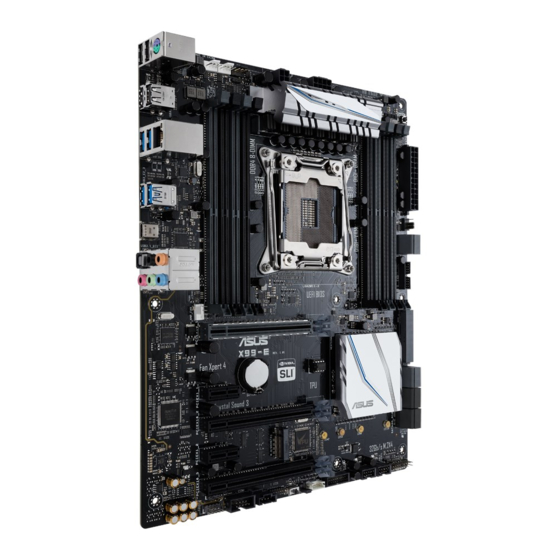
Page 18: Motherboard Layout
1.1.2 Motherboard layout Refer to 1.1.9 Internal connectors and 2.2.1 Rear I/O connection for more information about rear panel connectors and internal connectors. Chapter 1: Product Introduction... - Page 19 8. Clear RTC RAM jumper (2-pin CLRTC) 1-11 9. System panel connector (20-3 pin PANEL) 1-20 10. DirectKey connector (2-pin DRCT) 1-21 11. USB 2.0 connectors (10-1 pin USB1112; USB1314) 1-17 12. CPU Over Voltage jumper (3-pin CPU_OV) 1-12 13. T_Sensor connector (2-pin T_SENSOR1) 1-23 14. EZ XMP switch 15. TPM connector (14-1 pin TPM) 1-21 16. Thunderbolt header (5-pin TB_HEADER) 1-22 17. Serial port connector (10-1 pin COM) 1-23 18. Front panel audio connector (10-1 pin AAFP) 1-15 19. Digital audio connector (4-1 pin SPDIF_OUT) 1-15 20. M.2 Socket 3 1-22 ASUS X99-E Series...
-
Page 20: Central Processing Unit (Cpu)
1.1.3 Central Processing Unit (CPU) The motherboard comes with a surface mount LGA2011-v3 socket designed for Intel Core™ ® i7 processors. • Ensure that all power cables are unplugged before installing the CPU. • Upon purchase of the motherboard, ensure that the PnP cap is on the socket and the socket contacts are not bent. Contact your retailer immediately if the PnP cap is missing, or if you see any damage to the PnP cap/socket contacts/motherboard components. ASUS will shoulder the cost of repair only if the damage is shipment/ transit-related. • Keep the cap after installing the motherboard. ASUS will process Return Merchandise Authorization (RMA) requests only if the motherboard comes with the cap on the LGA2011-v3 socket. • The product warranty does not cover damage to the socket contacts resulting from incorrect CPU installation/removal, or misplacement/loss/incorrect removal of the PnP cap. Chapter 1: Product Introduction... -
Page 21: System Memory
1.1.4 System memory The motherboard comes with eight DDR4 (Double Data Rate 4) Quad Inline Memory Modules (DIMM) slots. A DDR4 module is notched differently from a DDR, DDR2, or DDR3 module. DO NOT install a DDR, DDR2, or DDR3 memory module to the DDR4 slot. Recommended memory configurations ASUS X99-E Series... - Page 22 ® com/kb/929605/en-us. • The design of the DIMM fan may vary. Ensure that the DIMM fan fits to the motherboard • The default memory operation frequency is dependent on its Serial Presence Detect (SPD), which is the standard way of accessing information from a memory module. Under the default state, some memory modules for overclocking may operate at a lower frequency than the vendor-marked value. To operate at the vendor-marked or at a higher frequency, refer to section 3.5 Ai Tweaker menu for manual memory frequency adjustment. • For system stability, use a more efficient memory cooling system to support a full memory load (8 DIMMs) or overclocking condition. • Memory modules with memory frequency higher than 2133MHz and their corresponding timing or the loaded XMP profile is not the JEDEC memory standard. The stability and compatibility of the memory modules depend on the CPU’s capabilities and other installed devices. • Always install the DIMMS with the same CAS Latency. For an optimum compatibility, we recommend that you install memory modules of the same version or data code (D/C) from the same vendor. Check with the vendor to get the correct memory modules. • ASUS exclusively provides hyper DIMM support function. • Hyper DIMM support is subject to the physical characteristics of individual CPUs. Load the X.M.P. or D.O.C.P. settings in the BIOS for the hyper DIMM support. • Visit the ASUS website for the latest QVL. Chapter 1: Product Introduction...
-
Page 23: Expansion Slots
1.1.5 Expansion slots Unplug the power cord before adding or removing expansion cards. Failure to do so may cause you physical injury and damage motherboard components. Slot Description Slot No. 40-LANE 28-LANE PCIe 3.0/2.0 x16_1 slot PCIe 3.0/2.0 x16_1 slot PCIe 2.0 x1_1 slot PCIe 2.0 x1_1 slot PCIe 3.0/2.0 x16_2 slot PCIe 3.0/2.0 x16_2 slot PCIe 2.0 x1_2 slot PCIe 2.0 x1_2 slot PCIe 3.0/2.0 x16_3 slot PCIe 3.0/2.0 x16_3 slot ASUS X99-E Series... - Page 24 40-LANE CPU PCI Express 3.0 operating mode VGA configuration PCIe 3.0/2.0 x16_1 PCIe 3.0/2.0 x16_2 PCIe 3.0/2.0 x16_3 x16 Single VGA/PCIe card (single VGA recommended) Dual VGA/PCIe cards Triple VGA/PCIe cards 28-LANE CPU PCI Express 3.0 operating mode VGA configuration PCIe 3.0/2.0 x16_1 PCIe 3.0/2.0 x16_2 PCIe 3.0/2.0 x16_3 x16 (single VGA Single VGA/PCIe card recommended)
-
Page 25: Onboard Buttons And Switches
1.1.6 Onboard buttons and switches Onboard buttons and switches allow you to fine-tune performance when working on a bare or open-case system. This is ideal for overclockers and gamers who continually change settings to enhance system performance. EZ XMP switch Enable this switch to overclock the installed DIMMs, allowing you to enhance the DIMM’s speed and performance. The EZ XMP LED (XLED1) lights up when you enable the EZ XMP switch. For the location of the EZ XMP LED, refer to section 1.1.8 Onboard LEDs. ASUS X99-E Series... - Page 26 • Refer to section 1.1.8 Onboard LEDs for the exact location of the DRAM_LED. • The DRAM_LED also lights up when the DIMM is not properly installed. Turn off the system and reinstall the DIMM before using the MemOK! function. • The MemOK! button does not function under Windows OS environment. ® • During the tuning process, the system loads and tests failsafe memory settings. It takes about 30 seconds for the system to test one set of failsafe settings. If the test fails, the system reboots and tests the next set of failsafe settings. The blinking speed of the DRAM_LED increases, indicating different test processes. • Due to memory tuning requirement, the system automatically reboots when each timing set is tested. If the installed DIMMs still fail to boot after the whole tuning process, the DRAM_LED lights continuously. Replace the DIMMs with ones recommended in the Memory QVL (Qualified Vendors Lists) in this user manual or at www.asus.com. • If you turn off the computer and replace DIMMs during the tuning process, the system continues memory tuning after turning on the computer. To stop memory tuning, turn off the computer and unplug the power cord for about 5–10 seconds. • If your system fails to boot up due to BIOS overclocking, press the MemOK! button to boot and load the BIOS default settings. A message will appear during POST reminding you that the BIOS has been restored to its default settings. • We recommend that you download and update to the latest BIOS version from www.asus.com after using the MemOK! function. Chapter 1: Product Introduction 1-10...
-
Page 27: Jumpers
1.1.7 Jumpers Clear RTC RAM jumper (2-pin CLRTC) This jumper allows you to clear the Real Time Clock (RTC) RAM in CMOS. You can clear the CMOS memory of date, time, and system setup parameters by erasing the CMOS RTC RAM data. The onboard button cell battery powers the RAM data in CMOS, which include system setup information such as system passwords. To erase the RTC RAM: Turn OFF the computer and unplug the power cord. Short-circuit pin 1-2 with a metal object or jumper cap for about 5-10 seconds. Plug the power cord and turn ON the computer. Hold down the <Delete> key during the boot process and enter BIOS setup to re-enter data. Except when clearing the RTC RAM, never remove the cap on CLRTC jumper default position. Removing the cap will cause system boot failure! • If the steps above do not help, remove the onboard battery and move the jumper again to clear the CMOS RTC RAM data. After the CMOS clearance, reinstall the battery. • You do not need to clear the RTC when the system hangs due to overclocking. For system failure due to overclocking, use the C.P.R. (CPU Parameter Recall) feature. Shut down and reboot the system so the BIOS can automatically reset parameter settings to default values. • Due to the chipset behavior, AC power off is required to enable C.P.R. function. You must turn off and on the power supply or unplug and plug the power cord before rebooting the system. ASUS X99-E Series 1-11... - Page 28 CPU Over Voltage jumper (3-pin CPU_OV) The CPU Over Voltage jumper allows you to set a higher CPU voltage for a flexible overclocking system, depending on the type of the installed CPU. To gain more CPU voltage setting, insert the jumper to pins 2-3. To go back to its default CPU voltage setting, insert the jumper to pins 1-2. Chapter 1: Product Introduction 1-12...
-
Page 29: Onboard Leds
1.1.8 Onboard LEDs POST State LEDs The POST State LEDs provide the status of these key components during POST (Power-On Self-Test): CPU, memory modules, VGA card, and hard disk drives. If an error is found, the critical component’s LED stays lit up until the problem is solved. EZ XMP LED (XLED1) This LED lights up when you enable the EZ XMP switch. ASUS X99-E Series 1-13... -
Page 30: Internal Connectors
1.1.9 Internal connectors Intel Serial ATA 6 Gb/s connectors (7-pin SATA6G_12, SATA 6G_34, SATA ® 6G_56/SATAEXPRESS, SATA6G_78, SATA6G_910) These connectors connect to Serial ATA 6 Gb/s hard disk drives via Serial ATA 6 Gb/s signal cables. If you installed Serial ATA hard disk drives, you can create a RAID 0, 1, 5, and 10 configuration with the Intel Rapid Storage Technology through the onboard Intel X99 ® ® chipset. • These connectors are set to [AHCI Mode] by default. If you intend to create a Serial ATA RAID set using these connectors, set the SATA Mode item in the BIOS to [RAID Mode]. Refer to section 3.6.3 PCH Storage Configuration for details. • Before creating a RAID set, refer to the manual bundled in the motherboard support DVD. • The SATAEXPRESS connector can support one SATA Express device or two SATA devices. - Page 31 Digital audio connector (4-1 pin SPDIF_OUT) This connector is for an additional Sony/Philips Digital Interface (S/PDIF) port. Connect the S/PDIF Out module cable to this connector, then install the module to a slot opening at the back of the system chassis. The S/PDIF module is purchased separately. Front panel audio connector (10-1 pin AAFP) This connector is for a chassis-mounted front panel audio I/O module that supports either HD Audio or legacy AC`97 audio standard. Connect one end of the front panel audio I/O module cable to this connector. • We recommend that you connect a high-definition front panel audio module to this connector to avail of the motherboard’s high-definition audio capability. • If you want to connect a high-definition or an AC’97 front panel audio module to this connector, set the Front Panel Type item in the BIOS setup to [HD] or [AC97]. ASUS X99-E Series 1-15...
- Page 32 USB 3.0 connectors (20-1 pin USB3_12, USB3_56) These connectors allow you to connect a USB 3.0 module for additional USB 3.0 front or rear panel ports. With an installed USB 3.0 module, you can enjoy all the benefits of USB 3.0 including faster data transfer speeds of up to 5 Gb/s, faster charging time for USB-chargeable devices, optimized power efficiency, and backward compatibility with USB 2.0. The USB 3.0 module is purchased separately. • Ensure to install the related driver to fully use the USB 3.0 ports under Windows ® • The plugged USB 3.0 device may run on xHCI or EHCI mode depending on the operating system’s setting. • These USB 3.0 ports support native UASP transfer standard in Windows 8 / ® Windows 8.1 and Turbo Mode when using USB 3.1 Boost feature. ® Chapter 1: Product Introduction 1-16...
- Page 33 USB 2.0 connectors (10-1 pin USB1112; USB1314) These connectors are for USB 2.0 ports. Connect the USB module cable to these connector, then install the module to a slot opening at the back of the system chassis. These USB connector complies with USB 2.0 specification that supports up to 480 Mb/s connection speed. DO NOT connect a 1394 cable to the USB connectors. Doing so will damage the motherboard! You can connect the front panel USB cable to the ASUS Q-Connector (USB) first, and then install the Q-Connector (USB) to the USB connector onboard if your chassis supports front panel USB ports. The USB 2.0 module is purchased separately. ASUS X99-E Series 1-17...
- Page 34 (4-pin CPU_FAN; 4-pin CPU_OPT; 4-pin W_PUMP; 4-pin H_AMP_ FAN; 5-pin EXT_FAN; 4-pin CHA_FAN) Connect the fan cables to the fan connectors on the motherboard, ensuring that the black wire of each cable matches the ground pin of the connector. • DO NOT forget to connect the fan cables to the fan connectors. Insufficient air flow inside the system may damage the motherboard components. These are not jumpers! Do not place jumper caps on the fan connectors! • Ensure that the CPU fan cable is securely installed to the CPU fan connector. • The CPU_FAN connector supports the CPU fan of maximum 1A (12 W) fan power. • The CPU_FAN, CHA_FAN, and EXT_FAN connectors support the ASUS FAN Xpert 4 feature on X99 platform. • The EXT_FAN connector supports 2 of 5 thermal sensor sources. • All fan connectors detect the type of fan installed and automatically switches the control modes. To configure the fan’s control mode, go to Advanced Mode > Monitor > CPU Q-Fan Control item in BIOS. • For better Q-Fan functions, we recommend using 4-pin PWM fans when you connect powerful fans (1A or above) onto the H_AMP_FAN connector. • Ensure to disable Q-Fan functions if you want to connect powerful 3-pin DC fans (1A or above) onto the H_AMP_FAN connector.
- Page 35 ATX power connectors (24-pin EATXPWR; 8-pin EATX12V_1; 4-pin EATX12V_2) These connectors are for ATX power supply plugs. The power supply plugs are designed to fit these connectors in only one orientation. Find the proper orientation and push down firmly until the connectors completely fit. • For a fully configured system, we recommend that you use a power supply unit (PSU) that complies with ATX 12 V Specification 2.0 (or later version) and provides a minimum power of 350 W. • DO NOT forget to connect the 8-pin EATX12V_1 power plug. Otherwise, the system will not boot. • We recommend that you use a PSU with a higher power output when configuring a system with more power-consuming devices. The system may become unstable or may not boot up if the power is inadequate. • If you want to use two or more high-end PCI Express x16 cards, use a PSU with 1000W power or above to ensure the system stability. ASUS X99-E Series 1-19...
- Page 36 System panel connector (20-3 pin PANEL) This connector supports several chassis-mounted functions. • System power LED (2-pin or 3-1 pin PLED) The 2-pin or 3-1 pin connector is for the system power LED. Connect the chassis power LED cable to this connector. The system power LED lights up when you turn on the system power, and blinks when the system is in sleep mode. • Hard disk drive activity LED (2-pin HDD_LED) This 2-pin connector is for the HDD Activity LED. Connect the HDD Activity LED cable to this connector. The HDD LED lights up or flashes when data is read from or written to the HDD. • System warning speaker (4-pin SPEAKER) This 4-pin connector is for the chassis-mounted system warning speaker. The speaker allows you to hear system beeps and warnings. • ATX power button/soft-off button (2-pin PWRSW) This connector is for the system power button. Pressing the power button turns the system on or puts the system in sleep or soft-off mode depending on the operating system settings. Pressing the power switch for more than four seconds while the system is ON turns the system OFF. • Reset button (2-pin RESET) This 2-pin connector is for the chassis-mounted reset button for system reboot without turning off the system power. • Chassis intrusion connector (2-pin CHASSIS) This connector is for a chassis-mounted intrusion detection sensor or switch. Connect one end of the chassis intrusion sensor or switch cable to this connector. The chassis intrusion sensor or switch sends a high-level signal to this connector when a chassis component is removed or replaced. The signal is then generated as a chassis intrusion event. Chapter 1: Product Introduction 1-20...
- Page 37 TPM connector (14-1 pin TPM) This connector supports a Trusted Platform Module (TPM) system, which securely stores keys, digital certificates, passwords and data. A TPM system also helps enhance network security, protect digital identities, and ensures platform integrity. The TPM module is purchased separately. DirectKey connector (2-pin DRCT) This connector is for the chassis-mounted button that supports the DirectKey function. Connect the button cable that supports DirectKey, from the chassis to this connector on the motherboard. Ensure that your chassis comes with the extra button cable that supports the DirectKey feature. Refer to the technical documentation that came with the chassis for details. ASUS X99-E Series 1-21...
- Page 38 Thunderbolt header (5-pin TB_HEADER) This connector is for the add-on Thunderbolt I/O card that supports Intel’s Thunderbolt Technology, allowing you to connect up to six Thunderbolt-enabled devices and a DisplayPort-enabled display in a daisy-chain configuration. The add-on Thunderbolt I/O card and Thunderbolt cables are purchased separately. M.2 socket 3 This socket allows you to install an M.2 (NGFF) SSD module. This socket supports PCIe 3.0 x4 M Key design and type 2242/2260/2280/22110 PCIe storage devices. The M.2 (NGFF) SSD module is purchased separately. Chapter 1: Product Introduction 1-22...
- Page 39 Thermal Sensor connector (2-pin T_SENSOR1) This connector is for the thermistor cable that monitors the temperature of the devices and the critical components inside the motherboard. Connect the thermistor cable and place the sensor on the device or the motherboard’s component to detect its temperature. Serial port connector (10-1 pin COM) These connectors are for the serial (COM) port. Connect the serial port module cable to one of these connectors, then install the module to a slot opening at the back of the system chassis. ASUS X99-E Series 1-23...
- Page 40 Chapter 1: Product Introduction 1-24...
-
Page 41: Chapter 2: Basic Installation
The diagrams in this section are for reference only. The motherboard layout may vary with models, but the installation steps are the same for all models. Install the ASUS Q-Shield to the chassis rear I/O panel. Place the motherboard into the chassis, ensuring that its rear I/O ports are aligned to the chassis’... - Page 42 Place nine screws into the holes indicated by circles to secure the motherboard to the chassis. DO NOT overtighten the screws! Doing so can damage the motherboard. Chapter 2: Basic Installation...
-
Page 43: Cpu Installation
Please note the order in opening/ closing the double latch. Follow the instructions printed on the metal sealing hatch or the illustrations shown below in this manual. The plastic cap will pop up automatically once the CPU is in place and the hatch properly sealed down. ASUS X99-E Series... - Page 44 Triangle mark Triangle mark Chapter 2: Basic Installation...
-
Page 45: Cpu Heatsink And Fan Assembly Installation
2.1.3 CPU heatsink and fan assembly installation Apply the Thermal Interface Material to the CPU heatsink and CPU before you install the heatsink and fan, if necessary. To install the CPU heatsink and fan assembly ASUS X99-E Series... -
Page 46: Dimm Installation
2.1.4 DIMM installation To remove a DIMM Chapter 2: Basic Installation... -
Page 47: Atx Power Connection
2.1.5 ATX power connection • DO NOT connect the 4-pin power plug only, the motherboard may overheat under heavy usage. • Ensure to connect the 8-pin power plug, or connect both the 8-pin and 4-pin power plugs. ASUS X99-E Series... -
Page 48: Sata Device Connection
2.1.6 SATA device connection Chapter 2: Basic Installation... -
Page 49: Front I/O Connector
2.1.7 Front I/O connector To install ASUS Q-Connector To install USB 2.0 connector To install front panel audio connector AAFP USB 2.0 To install USB 3.0 connector USB 3.0 ASUS X99-E Series... -
Page 50: Expansion Card Installation
2.1.8 Expansion card installation To install PCIe x16 cards To install PCIe x1 cards Chapter 2: Basic Installation 2-10... -
Page 51: Motherboard Rear And Audio Connections
* and ** : Refer to the tables on the next page for LAN port LEDs and audio port definitions. • The plugged USB 3.0 device may run on xHCI mode or EHCI mode, depending on the operating system’s setting. • USB 3.0 devices can only be used as data storage only. • We strongly recommend that you connect USB 3.0 devices to USB 3.0 ports for faster and better performance for your USB 3.0 devices. ASUS X99-E Series 2-11... - Page 52 * LAN ports LED indications Activity Link LED Speed LED Status Description Status Description ACT/LINK SPEED No link 10 Mbps connection Orange Linked Orange 100 Mbps connection Orange (Blinking) Data activity Green 1 Gbps connection Orange (Blinking Ready to wake up LAN port then steady) from S5 mode...
-
Page 53: Audio I/O Connections
2.2.2 Audio I/O connections Audio I/O ports Connect to Headphone and Mic Connect to Stereo Speakers Connect to 2.1 channel Speakers ASUS X99-E Series 2-13... - Page 54 Connect to 4.1 channel Speakers Connect to 5.1 channel Speakers If you are using Windows 8.1/10 platform, use only the light blue audio port for Side ® Speaker Out in a 6-channel configuration. Chapter 2: Basic Installation 2-14...
-
Page 55: Starting Up For The First Time
If you do not see anything within 30 seconds from the time you turned on the power, the system may have failed a power-on test. Check the jumper settings and connections or call your retailer for assistance. ASUS X99-E Series 2-15... -
Page 56: Turning Off The Computer
BIOS Beep Description One short beep VGA detected Quick boot set to disabled No keyboard detected One continuous beep followed by two No memory detected short beeps then a pause (repeated) One continuous beep followed by three No VGA detected short beeps One continuous beep followed by four Hardware component failure... -
Page 57: Chapter 3: Bios Setup
BIOS Setup Knowing BIOS The new ASUS UEFI BIOS is a Unified Extensible Interface that complies with UEFI architecture, offering a user-friendly interface that goes beyond the traditional keyboard- only BIOS controls to enable a more flexible and convenient mouse input. You can easily navigate the new UEFI BIOS with the same smoothness as your operating system. -
Page 58: Bios Setup Program
RTC RAM via the Clear CMOS button. • The BIOS setup program does not support the Bluetooth devices. Please visit ASUS website for the detailed BIOS content manual. BIOS menu screen The BIOS Setup program can be used under two modes: EZ Mode and Advanced Mode. -
Page 59: Ez Mode
Click to go to Advanced mode Loads optimized Search on the FAQ default settings Click to display boot devices Selects the boot device priority The boot device options vary depending on the devices you installed to the system. ASUS X99-E Series... -
Page 60: Advanced Mode
3.2.2 Advanced Mode The Advanced Mode provides advanced options for experienced end-users to configure the BIOS settings. The figure below shows an example of the Advanced Mode. Refer to the following sections for the detailed configurations. To switch from EZ Mode to Advanced Mode, click Advanced Mode(F7) or press the <F7> hotkey. - Page 61 This button above the menu bar allows you to view and tweak the overclocking settings of your system. It also allows you to change the motherboard’s SATA mode from AHCI to RAID mode. Refer to section 3.2.4 EZ Tuning Wizard for more information. ASUS X99-E Series...
- Page 62 Move your mouse over this button to show a QR code, scan this QR code on your mobile device to connect to the BIOS FAQ web page of the ASUS support website. You can also scan the following QR code:...
-
Page 63: Qfan Control
Click to activate DC Mode configured PWM Mode Select a profile to apply to Click to apply the fan setting your fans Click to undo the Click to go back to main menu changes Select to manually configure your fans ASUS X99-E Series... - Page 64 Configuring fans manually Select Manual from the list of profiles to manually configure your fans’ operating speed. Speed points Select to manually configure your fans To configure your fans: Select the fan that you want to configure and to view its current status. Click and drag the speed points to adjust the fans’...
-
Page 65: Ez Tuning Wizard
To start OC Tuning: Press <F11> on your keyboard or click from the BIOS screen to open EZ Tuning Wizard screen. Click OC then click Next. Select a PC scenario Daily Computing or Gaming/Media Editing, then click Next. ASUS X99-E Series... - Page 66 Select a Main Cooling System BOX cooler, Tower cooler, Water cooler, or I’m not sure, then click Next. After selecting the Main Cooling System, click Next then click Yes to start the OC Tuning. Creating RAID To create RAID: Press <F11> on your keyboard or click from the BIOS screen to open EZ Tuning Wizard screen.
- Page 67 Speed (RAID 5). After selecting the type of RAID, click Next then click Yes to continue the RAID setup. After the RAID setup is done, click Yes to exit the setup then click OK to reset your system. ASUS X99-E Series 3-11...
-
Page 68: My Favorites
My Favorites My Favorites is your personal space where you can easily save and access your favorite BIOS items. My Favorites comes with several performance, power saving, and fast boot related items by default. You can personalize this screen by adding or removing items. Chapter 3: BIOS Setup 3-12... - Page 69 • Configuration items such as Memory SPD Information, system time and date. Click Exit (ESC) or press <Esc> key to close Setup Tree Map screen. Go to My Favorites menu to view the saved BIOS items. ASUS X99-E Series 3-13...
-
Page 70: Main Menu
Main menu The Main menu screen appears when you enter the Advanced Mode of the BIOS Setup program. The Main menu provides you an overview of the basic system information, and allows you to set the system date, time, language, and security settings. Security The Security menu items allow you to change the system security settings. -
Page 71: Ai Tweaker Menu
(XMP) Technology, choose this item to set the profiles supported by your memory modules for optimizing the system performance. The [XMP] configuration option appears only when you install memory modules supporting the eXtreme Memory Profile (XMP) Technology. ASUS X99-E Series 3-15... - Page 72 ASUS MultiCore Enhancement [Auto] This item allows you to maximize the oveclocking performance optimized by ASUS core ratio settings. [Disabled] This item allows you to set to default core ratio settings. CPU Core Ratio This item allows you to set the CPU core ratios.
-
Page 73: Advanced Menu
EPU Power Saving Mode The ASUS EPU (Energy Processing Unit) sets the CPU in its minimum power consumption settings. Configuration options: [Disabled] [Enabled] Internal CPU Power Management The subitems in this menu allow you to set the CPU ratio and features. -
Page 74: Cpu Configuration
3.6.1 CPU Configuration The items in this menu show the CPU-related information that the BIOS automatically detects. The items in this menu may vary based on the CPU installed. Hyper-Threading This item allows a hyper-threading processor to appear as two logical processors, allowing the operating system to schedule two threads or processors simultaneously. -
Page 75: Pch Configuration
3.6.2 PCH Configuration PCI Express Configuration This item allows you to configure the PCI Express slots. PCIe Speed This item allows your system to automatically select the PCI Express port speed. Configuration options: [Auto] [Gen1] [Gen2] ASUS X99-E Series 3-19... -
Page 76: Pch Storage Configuration
3.6.3 PCH Storage Configuration While entering Setup, the BIOS automatically detects the presence of SATA devices. The SATA Port items show [Not Installed] if no SATA device is installed to the corresponding SATA port. Scroll down to display the other BIOS items. S.M.A.R.T. -
Page 77: System Agent (Sa) Configuration
Configuration options: [Disabled] [Enabled] Hot Plug These items appear only when the SATA Mode Selection is set to [AHCI] and allows you to enable or disable SATA Hot Plug Support. Configuration options: [Disabled] [Enabled] 3.6.4 System Agent (SA) Configuration ASUS X99-E Series 3-21... -
Page 78: Usb Configuration
3.6.5 USB Configuration The items in this menu allow you to change the USB-related features. The Mass Storage Devices item will only appear when a USB device is detected. USB Single Port Control This item allows you to enable or disable the individual USB ports. Refer to section 1.1.2 Motherboard layout for the location of the USB ports. -
Page 79: Onboard Devices Configuration
This item allows you to enable or disable the Asmedia USB 3.1 controller of your system. Configuration options: [Disabled] [Enabled] Asmedia USB 3.1 Battery Charging Support This item allows you to enable or disable the Asmedia USB 3.1 Battery Charging support of your system. Configuration options: [Disabled] [Enabled] ASUS X99-E Series 3-23... -
Page 80: Apm Configuration
RGB LED lighting [On] LEDs will always light up at the S0(Working), S3(Sleep), and S5(Soft off) states, but not at the S5 state when the “ErP Ready” is enabled. [Off] LEDs will not light up. RGB LED lighting effects This item allows you to set the RGB LED lighting effects. Configuration options: [Default] [Auto] [Static] [Breathing] [Strobing] [Color Cycle] The following item appears only when you set the RGB LED lighting effects to [Static], [Breathing], or [Strobing]. -
Page 81: Network Stack Configuration
3.6.9 Network Stack Configuration 3.6.10 HDD/SSD SMART Information This menu displays the SMART information of the connected devices. NVM Express devices do not support SMART information. ASUS X99-E Series 3-25... -
Page 82: Monitor Menu
Monitor menu The Monitor menu displays the system temperature/power status, and allows you to change the fan settings. Scroll down to display the other BIOS items. Optimize All Click this item to automatically detect the lowest speed and configure the minimum duty cycle for each fan. -
Page 83: Boot Menu
DRCT header. Setup Mode [Advanced Mode] This item allows you to go to Advanced Mode of the BIOS after POST. [EZ Mode] This item allows you to go to EZ Mode of the BIOS after POST. ASUS X99-E Series 3-27... - Page 84 ® ® • To access Windows OS in Safe Mode, press <F8> after POST (Windows 8 not supported). • To select the boot device during system startup, press <F8> when the ASUS Logo appears. Chapter 3: BIOS Setup 3-28...
-
Page 85: Tool Menu
3.9.1 ASUS EZ Flash 3 Utility This item allows you to run ASUS EZ Flash 3. When you press <Enter>, a confirmation message appears. Use the left/right arrow key to select a method, then press <Enter> to confirm your choice. -
Page 86: Secure Erase
To launch Secure Erase, click Tool > Secure Erase on the Advanced mode menu. Check the ASUS support site for a full list of SSDs tested with Secure Erase. The drive may become unstable if you run Secure Erase on an incompatible SSD. -
Page 87: Asus Overclocking Profile
Key in a profile number from one to eight, press <Enter>, and then select Yes. Load/Save Profile from/to USB Drive This item allows you to load or save profile from your USB drive, load and save profile to your USB drive. ASUS X99-E Series 3-31... -
Page 88: Asus Spd Information
3.9.4 ASUS SPD Information This item allows you to view the DRAM SPD information. Chapter 3: BIOS Setup 3-32... -
Page 89: Exit Menu
<Esc>, a confirmation window appears. Select Yes to discard changes and exit. Launch EFI Shell from filesystem device This item allows you to attempt to launch the EFI Shell application (shellx64.efi) from one of the available filesystem devices. ASUS X99-E Series 3-33... -
Page 90: Updating Bios
® ASUS EZ Flash 3: Updates the BIOS using a USB flash drive. ASUS CrashFree BIOS 3: Restores the BIOS using the motherboard support DVD or a USB flash drive when the BIOS file fails or gets corrupted. 3.11.1... -
Page 91: Asus Ez Flash 3
3.11.2 ASUS EZ Flash 3 ASUS EZ Flash 3 allows you to download and update to the latest BIOS through the Internet without having to use a bootable floppy disk or an OS-based utility. Updating through the Internet varies per region and Internet conditions. Check your local Internet connection before updating through the Internet. - Page 92 To update the BIOS by Internet: Enter the Advanced Mode of the BIOS setup program. Go to the Tool menu to select ASUS EZ Flash Utility and press <Enter>. Select by Internet. Press the Left/Right arrow keys to select an Internet connection method, and then press <Enter>.
-
Page 93: Asus Crashfree Bios 3
The BIOS file in the motherboard support DVD may be older than the BIOS file published on the ASUS official website. If you want to use the newer BIOS file, download the file at https://www.asus.com/support/ and save it to a USB flash drive. - Page 94 Chapter 3: BIOS Setup 3-38...
-
Page 95: Chapter 4: Raid Support
With the RAID 10 configuration you get all the benefits of both RAID 0 and RAID 1 configurations. Use four new hard disk drives or use an existing drive and three new drives for this setup. ASUS X99-E Series... -
Page 96: Installing Serial Ata Hard Disks
4.1.2 Installing Serial ATA hard disks The motherboard supports Serial ATA hard disk drives. For optimal performance, install identical drives of the same model and capacity when creating a disk array. To install the SATA hard disks for a RAID configuration: Install the SATA hard disks into the drive bays. - Page 97 When the RAID Level item is selected, press <Enter> to select the RAID level to create, and then press <Enter>. Under Select Disks, press <Enter> and select X for the disks you want to include in the RAID set. ASUS X99-E Series...
- Page 98 When the Strip Size item is selected, press <Enter> to select strip size for the RAID array (for RAID 0, 10 and 5 only), and then press <Enter>. The available strip size values range from 4 KB to 128 KB. The following are typical values: RAID 0: 128 KB RAID 10: 64 KB RAID 5: 64 KB...
- Page 99 <Enter>. The following screen appears: When the Delete item is selected, press <Enter>, then select Yes to delete the RAID volume and return to the Intel Rapid Storage Technology menu, or select No to ® cancel. ASUS X99-E Series...
-
Page 100: Intel ® Rapid Storage Technology Option Rom Utility
4.1.4 Intel Rapid Storage Technology Option ROM utility ® To enter the Intel Rapid Storage Technology Option ROM utility: ® Turn on the system. During POST, press <Ctrl> + <I> to display the utility main menu. RAID Volumes: None defined. Physical Devices: Port Device Model... - Page 101 Serial # Size Status ST3160812AS 9LS0HJA4 149.0GB Non-RAID Disk ST3160812AS 9LS0F4HL 149.0GB Non-RAID Disk ST3160812AS 3LS0JYL8 149.0GB Non-RAID Disk ST3160812AS 9LS0BJ5H 149.0GB Non-RAID Disk Select 2 to 6 to use in creating the volume. [↑↓]-Prev/Next [SPACE]-SelectDisk [ENTER]-Done ASUS X99-E Series...
- Page 102 Use the up/down arrow key to select a drive, and then press <Space> to select. A small triangle marks the selected drive. Press <Enter> after completing your selection. Use the up/down arrow key to select the strip size for the RAID array (for RAID 0, 10 and 5 only), and then press <Enter>.
- Page 103 (This does not apply to Recovery volumes) Are you sure you want to delete “Volume0”? (Y/N): Press <Y> to delete the RAID set and return to the utility main menu, or press <N> to return to the DELETE VOLUME menu. ASUS X99-E Series...
-
Page 104: Creating A Raid Driver Disk
Exiting the Intel Rapid Storage Technology Option ROM utility ® To exit the utility: From the utility main menu, select 6. Exit, then press <Enter>. The following warning message appears: [CONFIRM EXIT] Are you sure you want to exit? (Y/N): Press <Y>... -
Page 105: Appendix
Consult the dealer or an experienced radio/TV technician for help. The use of shielded cables for connection of the monitor to the graphics card is required to assure compliance with FCC regulations. Changes or modifications to this unit not expressly approved by the party responsible for compliance could void the user’s authority to operate this equipment. ASUS X99-E Series... - Page 106 IC: Canadian Compliance Statement Complies with the Canadian ICES-003 Class B specifications. This device complies with RSS 210 of Industry Canada. This Class B device meets all the requirements of the Canadian interference-causing equipment regulations. This device complies with Industry Canada license exempt RSS standard(s). Operation is subject to the following two conditions: (1) this device may not cause interference, and (2) this device must accept any interference, including interference that may cause undesired operation of the device.
- Page 107 ASUS Recycling/Takeback Services ASUS recycling and takeback programs come from our commitment to the highest standards for protecting our environment. We believe in providing solutions for you to be able to responsibly recycle our products, batteries, other components as well as the packaging materials.
- Page 108 доступний на: www.asus.com/support Cijeli tekst EU izjave o sukladnosti dostupan je na: www.asus.com/support Türkçe AsusTek Computer Inc., bu aygıtın temel gereksinimlerle ve ilişkili Čeština Společnost ASUSTeK Computer Inc. tímto prohlašuje, že toto Yönergelerin diğer ilgili koşullarıyla uyumlu olduğunu beyan eder.
-
Page 109: Asus Contact Information
+1-510-739-3777 +1-510-608-4555 Web site http://www.asus.com/us/ Technical Support Support fax +1-812-284-0883 Telephone +1-812-282-2787 Online support http://qr.asus.com/techserv ASUS COMPUTER GmbH (Germany and Austria) Address Harkort Str. 21-23, 40880 Ratingen, Germany +49-2102-959931 Web site http://www.asus.com/de Online contact http://eu-rma.asus.com/sales Technical Support Telephone +49-2102-5789555 Support Fax... - Page 110 DECLARATION OF CONFORMITY Per FCC Part 2 Section 2. 1077(a) Asus Computer International Responsible Party Name: , CA 94539. Address: 800 Corporate Way, Fremont Phone/Fax No: (510)739-3777/(510)608-4555 hereby declares that the product Product Name : Motherboard Model Number : X99-E...
Need help?
Do you have a question about the X99-E Series and is the answer not in the manual?
Questions and answers