Moxa Technologies AWK-3121 Quick Installation Manual
Hide thumbs
Also See for AWK-3121:
- User manual (90 pages) ,
- Quick installation manual (15 pages) ,
- Quick installation manual (15 pages)
Table of Contents
Advertisement
Quick Links
Download this manual
See also:
User Manual
Quick Installation Guide
Moxa Americas:
Toll-free: 1-888-669-2872
Tel:
1-714-528-6777
Fax:
1-714-528-6778
Moxa Europe:
Tel:
+49-89-3 70 03 99-0
Fax:
+49-89-3 70 03 99-99
Moxa India:
Tel:
+91-80-4172-9088
Fax:
+91-80-4132-1045
AWK-3121
Moxa AirWorks
Edition 7.0, June 2016
Technical Support Contact Information
www.moxa.com/support
2016 Moxa Inc. All rights reserved.
Moxa China (Shanghai office):
Toll-free: 800-820-5036
Tel:
+86-21-5258-9955
Fax:
+86-21-5258-5505
Moxa Asia-Pacific:
Tel:
+886-2-8919-1230
Fax:
+886-2-8919-1231
P/N: 1802031210016
*1802031210016*
Advertisement
Table of Contents

Related Manuals for Moxa Technologies AWK-3121


Summary of Contents for Moxa Technologies AWK-3121
-
Page 1: Quick Installation Guide
AWK-3121 Quick Installation Guide Moxa AirWorks Edition 7.0, June 2016 Technical Support Contact Information www.moxa.com/support Moxa Americas: Moxa China (Shanghai office): Toll-free: 1-888-669-2872 Toll-free: 800-820-5036 Tel: 1-714-528-6777 Tel: +86-21-5258-9955 Fax: 1-714-528-6778 Fax: +86-21-5258-5505 Moxa Europe: Moxa Asia-Pacific: Tel: +49-89-3 70 03 99-0... -
Page 2: Package Checklist
IP30 housing with LED indicators make the AWK-3121 a convenient yet reliable solution for any industrial wireless application. Package Checklist Moxa’s AWK-3121 is shipped with the following items. If any of these items is missing or damaged, please contact your customer service representative for assistance. -
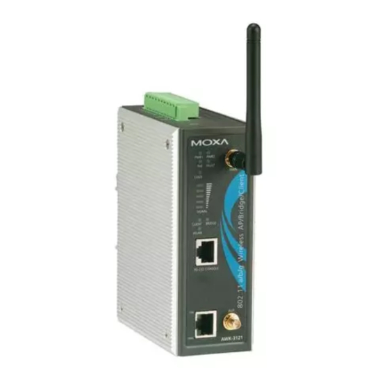
Page 3: Panel Layout Of The Awk-3121
Panel Layout of the AWK-3121 1. Grounding screw 2. Terminal block for PWR1, PWR2, relay, DI1, and DI2 3. Reset button 4. Heat dissipation orifices 5. System LEDs: PWR1, PWR2, PoE (discontinued starting with HW Rev 2.0.0), FAULT, and STATE LEDs 6. -
Page 4: Mounting Dimensions
The aluminum DIN-rail attachment plate should be fixed to the back panel of the AWK-3121 when you take it out of the box. If you need to reattach the DIN-rail attachment plate to the AWK-3121, make sure the stiff metal spring is situated towards the top, as shown in the figures below. -
Page 5: Wall Mounting (Optional)
STEP 2: Mounting the AWK-3121 to a wall requires 4 screws. Use the AWK-3121 device, with wall-mounting plates attached, as a guide to mark the correct locations of the 4 screws. The heads of the screws should be less than 6.0 mm in diameter, and the shafts should be less... -
Page 6: Grounding The Moxa Awk-3121
Before connecting the AWK to the DC power inputs, make sure that the DC power source voltage is stable. Grounding the Moxa AWK-3121 Grounding and wire routing help limit the effects of noise due to electromagnetic interference (EMI). Run the ground connection from the ground screw to the grounding surface prior to connecting devices. -
Page 7: Installations With Unstable Power Inputs
Installations with Unstable Power Inputs There are cases where the device has to be wired to the same power source as other equipment. In such cases if equipment such as motors that are connected in the circuit draw a large amount of current during operation, the transient voltage drop could potentially cause the AWK to become unstable. -
Page 8: Wiring The Redundant Power Inputs
Wiring the Redundant Power Inputs The top two pairs of contacts of the 10-contact terminal block connector on the AWK-3121’s top panel are used for the AWK-3121’s two DC inputs. Top and front views of the terminal block connector are shown here. -
Page 9: Communication Connections
The AWK-3121 has one RS-232 (8-pin RJ45) console port located on the front panel. Use either an RJ45-to-DB9 or RJ45-to-DB25 cable to connect the Moxa AWK-3121’s console port to your PC’s COM port. You may then use a console terminal program to access the AWK-3121 for console configuration. -
Page 10: Atex Information
Console Pinouts for 10-pin or 8-pin RJ45 10-Pin Description 8-Pin – – NOTE 1. The pin numbers for the DB9 and DB25 male connectors, and hole numbers for the DB9 and DB25 female connectors are labeled on the connector strip. However, the numbers are typically quite small, so you may need to use a magnifying glass to see the numbers clearly. -
Page 11: Led Indicators
LED Indicators The front panel of the Moxa AWK-3121 contains several LED indicators. The function of each LED is described in the table below. Color State Description Front Panel LED Indicators (System) Power is being supplied from power input 1. -
Page 12: Specifications
working properly. TP Port LED Indicators (Port Interface) TP port’s 100 Mbps link is active. 100M Green Blinking Data is being transmitted at 100 Mbps TP port’s 100 Mbps link is inactive. TP port’s 10 Mbps link is active. Amber Blink Data is being transmitted at 10 Mbps TP port’s 10 Mbps link is inactive. -
Page 13: Physical Characteristics
• Typ. 18±1.5 dBm @ 48 Mbps • Typ. 17±1.5 dBm @ 54 Mbps 802.11a: • Typ. 18±1.5 dBm @ 6 to 24 Mbps • Typ. 16±1.5 dBm @ 36 to 48 Mbps • Typ. 15±1.5 dBm @ 54 Mbps RX Sensitivity 802.11b: •... - Page 14 Warranty Period 5 years Details See www.moxa.com/support/warranty.aspx ATTENTION The AWK-3121 is NOT a portable mobile device and should • be located at least 20 cm away from the human body. The AWK-3121 is NOT designed for the general public. A •...
- Page 15 NOTE For installation flexibility, either the MAIN antenna or the AUX antenna may be selected for use. Make sure the antenna connection matches the antennas configured in the AWK-3121 web interface. To protect the connectors and RF module, all radio ports should be terminated by either an antenna or a terminator.
Need help?
Do you have a question about the AWK-3121 and is the answer not in the manual?
Questions and answers