Table of Contents
Advertisement
CQS
CQS
R-410A
Refrigerant
This unit contains R-410A high pressure refrigerant. Hazards exist that
could result in personal injury or death. Installation, maintenance, and
service should only be performed by an HVAC technician qualified in R-410A
refrigerant and using proper tools and equipment. Due to much higher
pressure of R-410A refrigerant, DO NOT USE service equipment or tools
designed for R22 refrigerant.
IMPORTANT: Do not release refrigerant to the atmosphere! If required
service procedures include the adding or removing of refrigerant, the service
technician must comply with all federal, state and local laws. The procedures
discussed in this manual should only be performed by a qualified HVAC
technician.
Operation / Maintenance / Service
Applies to:
Models YDHA, YDMA, and YDSA
DANGER
Obsoletes Form O-Y (11-15)
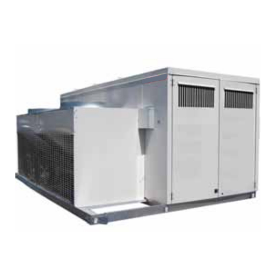
Packaged Rooftop Equipment
Model YDHA -
High Outside
Air (Conditioned
Ventilation)
Model YDMA -
Conditioned
Makeup Air
Model YDSA -
Space
Conditioning
Form O-Y P/N 273647R5, Page 1
Form O-Y (4-16)
Advertisement
Table of Contents
Troubleshooting

Related Manuals for Nortek YDHA


Summary of Contents for Nortek YDHA
- Page 1 Form O-Y (4-16) Obsoletes Form O-Y (11-15) Operation / Maintenance / Service Applies to: Models YDHA, YDMA, and YDSA Packaged Rooftop Equipment Model YDHA - High Outside Air (Conditioned Ventilation) Model YDMA - Conditioned Makeup Air R-410A Refrigerant Model YDSA -...
-
Page 2: Table Of Contents
1.0 General This booklet includes operation, maintenance, and service information for Model YDHA, Model YDMA, and Model YDSA. Before beginning any procedure, carefully review the information, paying particular attention to the warnings. Handling of refrig- erant should only be performed by a certified HVAC technician with knowledge of the requirements of R-410A refrigerant and in compliance with all codes and require- ments of authorities having jurisdiction. -
Page 3: Maintenance Schedule
IMPORTANT: Do not release refrigerant to the atmosphere! If required service procedures include the adding or removing of refrigerant, the service technician must comply with all federal, state and local laws. The procedures discussed in this manual should only be performed by a qualified HVAC technician familiar with R-410A refrigerant. -
Page 4: Control Locations
2.0 Maintenance Requirements (cont'd) 2.2 Control Locations FIGURE 1 - Access Doors and High and Low Voltage Inlet Air Control Hood Locations Supply Access Electrical / Control Condenser Compartments Section (See below.) Optional Gas or Electric Heat Section High Voltage Bus Bar - Compressor &... -
Page 5: Cabinet Size 1 Or 2 By Model & Size Cross-Referenced To Heat Section Size & Type
2.3 Cabinet Size 1 or 2 by Model & Size Cross-Referenced to Heat Section Size & Type Model YDHA YDMA YDSA Size 60 90 120 150 180 210 240 300 360 60 90 120 150 180 210 240 300 360 120 150 180 210 Nominal Cooling 7.5 10 12.5 15 17.5 20... -
Page 6: Maintenance And Service Procedures - Unit & Cooling Components
Replacement Filters by Model Size and Cabinet Size MERV 8 MERV 13 Pleated Cabinet Size Model(s) Model Sizes Size 16 x 25 211128 256666 YDHA & YDMA 090, 120, 150 20 x 24 222480 260828 YDHA & YDMA 180, 210, 240 16 x 25 211128 256666 YDSA... - Page 7 Filter Application by Cabinet & ER Wheel Sizes Cabinet 1" Permanent ER Wheel Size Model Model Size Filter Size Size 30" dia YDHA & YDMA 060, 090, 120, 150 16 x 16 104102 36" dia 090, 120, 150 20 x 20 101608 YDHA & YDMA...
-
Page 8: Supply Fan And Variable Frequency Drive
3.0 Maintenance and Service Procedures - Unit & Cooling Components (cont'd) Fan motors are permanently lubricated; lubrication is not required, During 3.2 Supply Fan maintenance, remove any accumulation of dirt and grease. The fan CFM was and Variable checked and balanced at startup. To recheck, follow the instructions in the installation Frequency Drive manual, Form I-Y, Paragraph 10.3. -
Page 9: Optional Dampers And Damper Actuator
3.0 Maintenance and Service Procedures - Unit & Cooling (cont'd) 3.2 Supply Fan and Variable Frequency Drive (cont'd) Function: The airflow proving switch is a pressure switch that verifies to the main Air Proving Switch controller that the supply fan is operating. If equipped with power exhaust or an P/N 234712 energy recovery wheel, there is a second air proving switch that verifies the exhaust Set Point 0.10 I.W.C. -
Page 10: Condenser Fans
3.0 Maintenance and Service Procedures - Unit & Cooling (cont'd) 3.4 Condenser Fans Depending on the model size, there are two or four condenser fans. Fan motors may be either standard efficiency or ECM speed control. If parts need to be replaced, use only factory authorized replacement parts. - Page 11 FIGURES 8 through 14, shown on pages 11 through 14. Thermostat Expansion (TXV) Valves by Circuit and P/N Thermostatic Model / Size DH - Low Enthalpy DH - High Enthalpy Expansion Valve YDHA & YDMA 060 234987 207303 YDHA 090 220556 207303 YDMA 090...
- Page 12 3.0 Maintenance and Service Procedures - Unit & Cooling (cont'd) 3.5 Coils and Related Components (cont'd) FIGURE 9 - Cooling Circuits - Models Circuit A YDHA and YDMA Circuit B Sizes 120 and 150 Model JDHA 120 and 150 (Cabinet 1) Circuit A...
- Page 13 Circuit B Model JDHA 300 and 360 (Cabinet 3) Circuit A FIGURE 12 - Cooling Circuits - Models YDHA and YDMA Sizes 300 and 360 Valves Circuit B Circuit A Equilizer Tube Compressor Circuit B (Circuit B) Filter Drier Filter Drier...
-
Page 14: Hot Gas Bypass
3.0 Maintenance and Service Procedures - Unit & Cooling (cont'd) 3.5 Coils and Related Components (cont'd) Optional Modulating Reheat (cont'd) FIGURE 14 - Optional DH Circuit (Option RPLE High Enthalpy Model JDHA 300 & 360 (Cabinet 3) Reheat Pump or Option RPHE Low Enthalpy Reheat Pump Circuit A &... - Page 15 FIGURE 16 - Cooling Circuit B with Optional Bypass Valve (Option AUC8) Hot Gas Bypass Check Valve at the Evaporator Coil Model JDHA 120 and 150 (Cabinet 1) with Option AUC8 Circuit B with Optional Hot Gas Bypass Model JDHA 180, 210, and 240 (Cabinet 2) with Option AUC8 Model JDHA 300 and 360 (Cabinet 3) with Option AUC8 Shutoff Shutoff...
- Page 16 3.0 Maintenance and Service Procedures - Unit & Cooling (cont'd) 3.5 Coils and Related Components (cont'd) Low Ambient Control, Option BE8 (cont'd) Install sensor(s) to the top of the liquid line where the line exits the condenser coil Installation of Liquid as shown below in sketch.
-
Page 17: Check Refrigerant Pressure And Temperatures (Subcooling And Superheat)
Temperature to Use Temperature to Resistance table shown below to verify proper sensor operation. Resistance Table Install sensor(s) to the top of the liquid line where the line exits the condenser coil Installation of Liquid as shown below in sketch. A liquid line sensor will be required for each independent Line Sensor(s) refrigerant circuit. - Page 18 3.0 Maintenance and Service Procedures - Unit & Cooling (cont'd) 3.6 Check Refrigerant Pressure and Temperatures (subcooling and superheat) (cont'd) Check SUBCOOLING Measure and record temperature and pressure of the liquid line at the condenser coil outlet. STEP 1) Record Measurements: Temperature = ________°F (°C) and Pressure = ________ psig STEP 2) From Temperature/Pressure Conversion Chart (page 17), convert Measured Pressure (STEP 1) to ________°F (°C) STEP 3) Subtract Measured Temperature (STEP 1) from Temperature from Conversion Chart (STEP 2)
- Page 19 Temperature/Pressure Conversion Chart R-410A Refrigerant R-410A Refrigerant R-410A Refrigerant R-410A Refrigerant R-410A Refrigerant Pressure Temperature Pressure Temperature Pressure Temperature Pressure Temperature Pressure Temperature °F °C °F °C °F °C °F °C °F °C -48.3 49.5 -17.2 77.0 -7.2 112.2 218.2 23.9 -45.6 50.9...
- Page 20 Crankcase Size Compressor 216454 ZP182KCE-TW5 Crankcase Crankcase Compressor Heater Heater Compressor Compressor Heater Heater 216455 ZP182KCE-TWD 208-240/1/60 272634 216394 216456 ZP182KCE-TWE YDHA & 262801 216394 259288 216394 259288 216394 208-240/3/60 216689 ZP83KCE-TF5 YDMA 480/3/60 262802 216396 259355 216396 259355 216396...
- Page 21 Circuit A has a modulating capacity compressor. Each modulating compressor has Modulating Cooling a digital controller. The digital controller in the electrical compartment (See FIGURE 1 on page 4, and FIGURE 15, page 14) is the electronic interface between the com- pressor and the system controller.
-
Page 22: And Replacement
3.0 Maintenance/Service Procedures - Unit & Cooling (cont'd) 3.7 Compressor Use a high temperature torch to disconnect the suction line and the discharge line from the compressor. Operation, d) Remove the mounting bolts and the compressor. Save the mounting hardware to Maintenance, attach the grommets and sleeves shipped with the replacement compressor. - Page 23 3.7 Compressor change the filter drier any time the circuit is opened. It is recommended to use a tubing cutter when cutting out a filter drier as the Operation, desiccant absorbs and holds moisture better when it is cool. Heat from a torch may Maintenance, cause moisture to leave the filter and be absorbed in the oil.
- Page 24 3.0 Maintenance/Service Procedures - Unit & Cooling (cont'd) 3.7 Compressor CAUTION: Do not use the replacement compressor as an Operation, evacuation assist and never apply voltage to a compressor while Maintenance, it is in a vacuum. See Hazard Levels, page 2. Replacement Moisture and air are harmful to the system because they increase the condensing (cont'd)
- Page 25 Identified by Circuit Model Size High Enthalpy Enthalpy YDHA YDMA YDSA • Step 10. System Startup Assure voltage to compressor does not drop below minimum allowable voltage (e.g. 187 volts for 230/208-3-60, 415 volts for 460/3/60, 518 volts for 575/3/60) during the period the compressor is trying to start.
- Page 26 3.0 Maintenance/Service Procedures - Unit & Cooling (cont'd) Record the ambient temperature. Adjust the system controller so that a call for 3.7 Compressor cooling exists. Operation, NOTE: Outdoor ambient lockouts may prevent mechanical cooling. Temporarily Maintenance, override lockouts by lowering the cooling setpoint. When testing is complete, reset the controller.
-
Page 27: Other Controls
CAUTION: After cleanup is complete, remove the suction line filter drier. See Hazard Levels, page 2. d) Verify subcooling and superheat (refer to Step 11). e) When the system is operating properly, remove the gauges. Or, IF the oil measured in Step 2 was not significantly less than that shown in the table on page 20 or the acid test in Step 2 did not indi- cate a compressor burnout, continue to the review in Step 13. -
Page 28: Energy Recovery Wheel, Option Ew
4.0 Maintenance/Service Procedures - Power Exhaust & Energy Recovery (cont'd) 4.2 Energy The energy recovery wheel including power exhaust is an integral part of the system. Recovery FIGURE 20 - Energy Wheel, Option EW Recovery Wheel Optional Preheat Elements Outside Sensor Power Exhaust... - Page 29 4.2 Energy Recovery Wheel, Option EW (cont'd) □ Clean the Wheel Segments WARNING □ Gently brush off any loose dirt and dust. Weight of the installed segments will cause the □ To wash the segments, use a non-acid based wheel to accelerate in rotation. Failure to maintain (evaporator) coil cleaner or alkaline detergent control of the wheel rotation while re-installing solution.
- Page 30 4.0 Maintenance/Service Procedures - Power Exhaust & Energy Recovery (cont'd) 4.2 Energy Recovery Wheel, Option EW (cont'd) FIGURE 21 - Checking the Seals (cont'd) Wheel Rotation Folded Paper Feeler Gauge Slide seal (shown in gray) toward wheel Adjusting Screws until a slight friction on the feeler gauge (When adjusting is detected when gauge is moved along seal, loosen only;...
-
Page 31: Temperature Sensor
Optional Preheat If equipped with optional preheat, one or two 10kw electric heat modules are located (frost Control) in the inlet air stream. Preheat operation is controlled by the system controller and is commanded ON when the supply air discharge sensor signals a temperature reading of 33°F (0.56°C). -
Page 32: Maintenance/Service Procedures - Gas Heat Section
5.0 Maintenance/Service Procedures - Gas Heat Section This gas heat section will operate with a minimum of maintenance. To ensure long life and satisfactory performance, a heater that is operated under normal conditions should be inspected and cleaned at the start of each heating season. If the heater is operating in an area where an unusual amount of dust or soot or other impurities are present in the air, more frequent maintenance is recommended. - Page 33 (120 seconds) and return to standby mode. NOTE: For detailed information on the sequence of operation for the heat sections, refer to section 3.5 Heating Staging Control, in the Model YDSA and YDHA Manual for Space Temperature Control System Options D19 (form CP-Y-D19) or option D21 (form CP-Y-D21).
- Page 34 NOTE: For detailed information on the sequence of operation for the heat sections, refer to section 3.5 Heating Staging Control, in the Model YDSA and YDHA Manual for Space Temperature Control System Options D19 (form CP-Y-D19) or option D21 (form CP-Y-D21).
- Page 35 Vent Temperature Limit Switch (High Efficiency Models Only) The vent temperature limit switch is located on the discharge of the combustion air blower (venter) and its purpose is to prevent the vent gas temperature from exceed- ing a temperature that will harm the PVC vent pipe. If the vent temperature limit switch is activated, the cause must be determined and corrected before the heater is placed back into operation.
- Page 36 5.0 Maintenance/Service Procedures - Gas Heat Section (cont'd) 5.1 Gas Heat Controls (cont'd) Depending on the heat section and gas control selected, all gas trains have one or Operating Gas Valve - two single-stage and/or two-stage combination gas valves. These gas valves must be checked annually to ensure that they are shutting off gas flow completely;...
-
Page 37: Combustion Air And Venting
Optional Gas Location: Low pressure switch is at the entrance to the gas train. The high pressure switch is at the burner end. See FIGURE 24, page 33 or 25, page 34. Pressure Switches Function: Monitors gas pressure and shuts down the heat section if gas pressure becomes too low or too high. - Page 38 5.0 Maintenance/Service Procedures - Gas Heat Section (cont'd) 5.2 Combustion Air and Venting (cont'd) Combustion Air Switches for Sea Level to 6000 ft. (1830 m) High Pressure Switch Low Pressure Switch (AG73 & AG74 Only) 230, 460, 208V Heat Heat 575V Startup Equilibrium...
- Page 39 Combustion Air Switches for Above 6000 ft. (1830 m) - (cont’d) High Pressure Switch High Pressure Switch Heat Heat Heat Heat Setpoint Label Switch Setpoint Label Switch Section Size(s) Section Size(s) Color Color Option (Btuh) Option (Btuh) Negative Pressure (iwc) Negative Pressure (iwc) 75,000 1.35...
-
Page 40: Vent Maintenance And Operation
5.0 Maintenance/Service Procedures - Gas Heat Section (cont'd) Vent Maintenance 5.3 Vent Maintenance Remove dirt and grease from the venter motor housing. The venter motor is perma- nently lubricated; do not lubricate. Carefully clean the venter wheel assembly, being and Operation cautious not to bend the wheel. -
Page 41: Burner And Heat Exchanger
5.4 Burner and Heat Inspect the gas heat section annually to determine if cleaning is necessary. If there is an accumulation of dirt, dust, and/or lint, clean the compartment. Exchanger CAUTION: Use of eye protection is recommended. (Requires a wire brush, cleaning cloth, Inspect and Clean the Burner an automotive type... -
Page 42: Maintenance/Service Procedures - Electric Heat Section
6.0 Maintenance/Service Procedures - Electric Heat Section Electric Heating A call for mechanical heat will occur when the discharge air temperature is 5°F(2.8°C) below the active setpoint. When the OAT is below 65°F/18°C (Heating Operation, Elements Lockout SP), the unit enables the mechanical heat to maintain the active setpoint. and Controls The modulated heat output will be set to 30% output and NO8 will be ON. -
Page 43: Troubleshooting
7.0 Troubleshooting 7.1 Troubleshooting - Refrigeration IMPORTANT: Do not release refrigerant to the atmosphere! If required service procedures include the adding or removing of refrigerant, the service technician must comply with all federal, state and local laws. The procedures discussed in this manual should only be performed by a qualified HVAC technician. - Page 44 7.0 Troubleshooting (cont'd) 7.1 Troubleshooting - Refrigeration (cont'd) General Refrigeration Circuit (cont'd) SYMPTOM POSSIBLE CAUSE REMEDY F. Noisy unit 1. Blower rotational noise. 1. Check blower, motor and drive for faulty adjustment or noisy bearings, loose parts, and/or blower out of balance. operation.
-
Page 45: Troubleshooting Compressor Digital Controller
7.2 Troubleshooting Compressor Digital Controller General - The digital controller is located in the electrical compartment and acts as the interface between the digital compressor and the unit controller. If the unit interface display indicates critical Alarm Code 17, Modulating Capacity Compressor Failure, check the LED lights on the digital controller. -
Page 46: Troubleshooting The Heat Section
7.0 Troubleshooting (cont'd) 7.2 Troubleshooting Compressor Digital Controller (cont'd) LED State Indicates Additional Information Color CODE Solid Digital compressor The installed digital compressor controller can be tested controller failure to verify that it is working properly. In each test, 24VAC must be supplied to 24VAC and 24COM. - Page 47 7.3.2 General Troubleshooting - Gas Heat Section - (Option G__ or H__) PROBLEM PROBABLE CAUSE REMEDY Venter motor 1. No power to unit. 1. Turn on power; check supply fuses or main circuit breaker. will not start 2. No 24 volt power to ignition system circuit 2.
-
Page 48: Index
Keep all booklets for future reference. Specifications & illustrations subject to change without notice and without incurring obligations. ©Nortek Global HVAC, LLC 2016. All rights reserved. All marks are the property of their respective organizations. O’Fallon, MO I Printed in U.S.A. (4/16)
Need help?
Do you have a question about the YDHA and is the answer not in the manual?
Questions and answers