Table of Contents
Advertisement
Available languages
Available languages
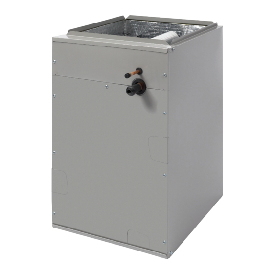
C74BA & C74BH Series Split System Indoor Cased/Uncased Coils With Orifice
INSTALLATION INSTRUCTIONS
IMPORTANT
ATTENTION INSTALLERS:
It is your responsibility to know this product better than your customer. This includes being able to install the
product according to strict safety guidelines and instructing the customer on how to operate and maintain the
equipment for the life of the product. Safety should always be the deciding factor when installing this product
and using common sense plays an important role as well. Pay attention to all safety warnings and any other
special notes highlighted in the manual. Improper installation of the furnace or failure to follow safety warnings
could result in serious injury, death, or property damage.
These instructions are primarily intended to assist qualified individuals experienced in the proper installation
of this appliance. Some local codes require licensed installation/service personnel for this type of equipment.
Please read all instructions carefully before starting the installation. Return these instructions to the customer's
package for future reference.
DO NOT DESTROY. PLEASE READ CAREFULLY & KEEP IN A SAFE PLACE FOR FUTURE REFERENCE.
Advertisement
Table of Contents

Related Manuals for Nortek C74BA Series


Summary of Contents for Nortek C74BA Series
- Page 1 C74BA & C74BH Series Split System Indoor Cased/Uncased Coils With Orifice INSTALLATION INSTRUCTIONS IMPORTANT ATTENTION INSTALLERS: It is your responsibility to know this product better than your customer. This includes being able to install the product according to strict safety guidelines and instructing the customer on how to operate and maintain the equipment for the life of the product.
-
Page 2: Important Safety Information
IMPORTANT SAFETY INFORMATION WARNING: Please read all instructions before servicing this equipment. Pay attention to all safety warnings and any other special This unit must be installed in accordance with notes highlighted in the manual. Safety markings are used the instructions outlined in this manual during frequently throughout this manual to designate a degree or the installation, service, and operation of this level of seriousness and should not be ignored. -
Page 3: General Information
COIL INSTALLATION • Close-off plates are available in some air filter kits. Refer to the Replacement Parts List for available part numbers. Install the necessary close-off plates around the refrigerant WARNING: lines and drain line where required. Reinstall all inner and outer panels of the furnace/air handler that were previously ELECTRICAL SHOCK, FIRE OR removed when installing the indoor coil. -
Page 4: Downflow Installations
NOTE: The holes in the drain pan extension should be 11. Reinstall the coil access door. pressed over the nibs molded into the drain pan. Which 12. Restore electrical power to the furnace. pair of holes to use will depend on whether the unit is Downflow Installations installed horizontal left or horizontal right. - Page 5 CAUTION: To prevent damage to the unit or internal components, it is recommended that two wrenches be used when loosening or tightening nuts. Do not over tighten! 5. Realign the assembly nut on the distributor body and hand tighten both components. Mark a line on both bodies and then tighten an additional 1/4 turn using two wrenches.
-
Page 6: Completing The Installation
Air Filter CAUTION: Air filters are not supplied as an integral part of this coil; It is recommended that a wet rag be wrapped around however, an air filter kit is available. Refer to the Replacement Parts List for available part numbers. the suction line in front of the close off plate before applying heat. - Page 7 3 1/8 2 1/2 19 1/2 Figure 5. C74 Uncased Coil Dimensions (Without TXV) Figure 6. C74 Cased Coil Dimensions...
- Page 8 UPFLOW & DOWNFLOW UNITS A-CABINETS B-CABINETS C-CABINETS D-CABINETS 018U-A 02430U-A 018U-B 02430U-B 03642U-B 02430U-C 03642U-C 048U-C 042U-D 048U-D C74BAM NOMINAL CAPACITY, MIN BTUH 24,000 24,000 36,000 24,000 36,000 18,000 18,000 48,000 42,000 48,000 NOMINAL CAPACITY, MAX BTUH 30,000 30,000 42,000 30,000 42,000 INSTALLED ORIFICE SIZE (IN.)
-
Page 10: Notice D'installation
Serpentins coffrés intérieurs pour système multi-blocs séries C74BA et C74BH avec orifice NOTICE D’INSTALLATION IMPORTANT REMARQUE À L’INTENTION DES INSTALLATEURS : Il est de votre responsabilité de mieux connaître ce produit que votre client. Cela inclut la capacité d’installer le produit conformément aux directives de sécurité... -
Page 11: Renseignements Importants Sur La Sécurité
RENSEIGNEMENTS IMPORTANTS SUR LA AVERTISSEMENT : SÉCURITÉ Veuillez lire toutes les instructions avant d’entretenir cet équipement. Cet appareil doit être installé conformément aux Prêtez attention à tous les avertissements de sécurité et toute instructions contenues dans ce manuel, et ce, autre remarque spéciale donnée dans le manuel. -
Page 12: Renseignements Généraux
Installations horizontales MISE EN GARDE : Les serpentins C74BA peuvent être installés horizontalement, mais la fournaise et les boîtiers de serpentins doivent être solidement fixés ensemble avant l’installation du serpentin. Une trousse de bac L’appareil doit être à l’équerre et de niveau pour de vidange horizontale doit aussi être installée sous le serpentin. - Page 13 Dépressurisation du système MISE EN GARDE : 1. Retirez le capuchon (Figure 1) du bout de la conduite de liquide. 2. Vérifiez la pressurisation en enfonçant la vanne Schrader sur le L’appareil doit être retiré et mis au rebut pour assurer bout de la conduite de liquide.
-
Page 14: Drain À Condensat
extérieur. Assurez-vous que les bouts sont ronds, propres et sans bavures. 6. Placez le passe-fils sur la conduite de succion de la canalisation. REMARQUE : N’installez PAS le passe-fils dans l’entrée défonçable de la porte à ce point-ci. Laissez suffisamment d’espace pour souder le joint. -
Page 15: Finalisation De L'installation
• La méthode d’élimination du condensat varie selon les codes locaux. Consultez les codes locaux ou les autorités qui ont juridiction pour connaître les restrictions et les exigences de mise au rebut appropriée du condensat. • Tous les bacs à condensat sont pourvus de branchements d’évacuation primaire et secondaire pour être conformes aux exigences du FHA. - Page 16 3 1/8 2 1/2 19 1/2 Figure 5. Dimensions du serpentin non coffré C74 (sans détendeur thermostatique) VUE D’AVANT VUE DE DESSUS Figure 6. Dimensions du serpentin coffré C74...
- Page 17 APPAREILS ASCENDANTES ET DESCENDANTES ARMOIRE A ARMOIRE B ARMOIRE C ARMOIRE D 018U-A 02430U-A 018U-B 02430U-B 03642U-B 02430U-C 03642U-C 048U-C 042U-D 048U-D C74BAM , BTUH 24,000 24,000 36,000 24,000 36,000 APACITé NOMINALE 18,000 18,000 48,000 42,000 48,000 , BTUH 30,000 30,000 42,000 30,000...
- Page 20 Spécifications et illustrations sujettes à changements sans préavis ou sans aucune obligation. (06/22) O’Fallon, MO, © Nortek Global HVAC LLC 2022. Tous droits réservés. Specifications & illustrations subject to change without notice or incurring obligations (06/22). O’Fallon, MO, © Nortek Global HVAC LLC 2022. All Rights Reserved.
Need help?
Do you have a question about the C74BA Series and is the answer not in the manual?
Questions and answers